Upright LX31 User manual

LX31 / LX41
Electric and Bi-Energy Models
Serial Numbers 4022 - Current
P/N 067448-023

Call Toll Free in U.S.A.
1-800-926-LIFT
UpRight, Inc.
801 South Pine Street
Madera, California 93637
TEL: 559-662-3900
FAX: 559-673-6184
PARTS: 1-888-UR-PARTS
PARTS FAX: 1-800-669-9884
UpRight
Unit S1, Park West Industrial Park
Friel Avenue
Nangor Road
Dublin 12, Ireland
TEL: +353 1 620 9300
FAX: +353 1 620 9301
When contacting UpRight for service or parts information, be sure to include the MODEL and SERIAL NUMBERS
from the equipment nameplate. Should the nameplate be missing, the SERIAL NUMBER is also stamped on top of
the chassis above the front axle pivot.
LX31 / LX41
Electric and Bi-Energy

Model Modello
Modell Verticaal model
Modele Malli
Modelo
Serial number Serienummer
Matricola Numero de serie
Sarajanumero Matricola
Notified body
Notifizierte Stelle
Organisme notifie Technische Prufstelle
Organismo notificado Dienstbier & Pix
Aangemelde instantie Hundert Beete 13
Myndighet D-91334 Hemhofen
Avendte harmoniserte standarder DEUTSCHLAND
Udpeget organ
Asiasta on tehty ilmoitus seuraaville tahoille ID Number CE 0533
Ente Notificatore
E Type Examination ertificate number
E -Typenprufung Zertifikat-Nr
Examen type E Numero de ertificat
Inspeccion tipo E Numero de certificado
Attestato di certificazione E nr
Onderzoek van het type E ertificaatnummer
EU typkontroll ertifieringsnummer
EF-typeproving Sertifikatnummer
EF-typegodkendelse Nummer pa typeattest
EU-tyypitarkastuksen nr.
David D. White Date
Senior VP, Global Engineering Datum
Leiter Qualit tssicherung Fecha
Directeur de l Assurance Qualite Data
Gerente de Garantia de alidad Dato
Responsabile Garanzia di Qualit Paivamaara
Kwaliteitscontrole Manager
Kvalitetskontroll hef
Kvalitetssikringssjef
Kvalitetssikringschef
Laadunvalvoja
EC Declaration of Conformity of Machinery
EC-Konformitätserklärung für Maschinen
Declaration De Conformite CE pour les Machines
Declaracion De Conformidad CE Para Maquinaria
Dichiarazione Di Conformità CE Per Le Macchine
CE Conformiteitsverklaring voor Machinerie
EU Deklaration Avseende Överensstammelse För Maskinutrustni
n
EF-Samsvarserklaering For Maskiner
EF-Overensstemmelseserklaering for Maskiner
EU Vaatimustenmukaisuusvakuutus
Manufacturer UpRight, Inc. Fabrikant
Hersteller 901 South Pine Street Tillverkare
Fabricant Madera, CA 93637 USA Produsent
Fabricante Tel: (559) 662-3900 Valmistaja
Fabbricante FAX: (559) 673-6184
www.upright.com
Authorized Representative
Autorisierte Vertretung
Representant autorise UpRight International Manufacturing Lt
d
Representante autorizado trading as UpRight Ireland
Mandatario Unit S1, Park West Industrial Park
Erkend vertegenwoordiger Friel Avenue, Nangor Road
Auktoriserad representant Dublin 12, IRELAND
Autorisert representant Tel: (353) 1 620 9300
Represenentant FAX: (353) 1 620 9301
Valtuutettu edustaja
Description....................................... Aerial Work Platform
Bezeichnung.................................... Arbeitsbühne
Description....................................... Plate-forme elevatrice de personnel
Descripcion...................................... Platforma aerea de trabajo con motor
Descrizione...................................... Piattaforma di sollevamento motorizzat
Beschrijving ..................................... Mechanisch aangedreven werkplatfor
m
Beskrivning...................................... Höj-och sänkbar arbetsplattform
Beskrivelse ...................................... Selvgående arbetsplattform
Beskrivelse ...................................... Motordrevet lofteplatform
Kuvaus............................................. Konevoimalla toimiva nostolava
Selvgående personarbetslift
00
Form 060562-000 Revision 0
LX31 / LX41
4275 +
LX31 0533 86 01
LX41 0533 87 01
March 2001

ENGLISH DEUTSCH NEDERLANDS FRANCAIS ITALIANO
SVENSKA ESPAÑOLSUOMI DANSK NORSK
The Machine specified herein complies with the following provisions:
Directive As amended by Directive Harmonized Standards
98/37/EC EN60204-1:1997 Safety of Machinery
89/336/EEC 93/68/EEC EN50081-1:1992 Electromagnetic
EN50082-1:1992 compatibility
Die obengenannte Maschine entspricht den folgenden Bestimmungen:
Richtlinie Geändert durch Richtlinien Harmonisierte Normen:
98/37/EC EN60204-1:1997 Maschinensicherheit –
Elecktrische
Maschinenausrüstung
89/336/EEC 93/68/EEC EN 50081-1:1992 Elektromagnetische
EN 50082-1:1992 Kompatibilität
De bovenvermelde machine voldoet aan de volgende voorwaarden:
Zoals gewijzigd
Richtlijn door richtlijnen Aanvaarde geharmoniseerde normen:
98/37/EC EN60204-1:1997 Veiligheid van machinerie
89/336/EEC 93/68/EEC EN50081-1:1992 Elektromagnetische
EN50082-1:1992 compatibiliteit
La machine décrite ci-dessus est conforme aux normes ci-dessous:
Directive Amendée par la directive Normes harmonisées adoptées
98/37/EC EN60204-1:1997 Sécurité des machines
89/336/EEC 93/68/EEC EN50081-1:1992 Compatibilité
EN50082-1:1992 électromagnétique
La macchina sopra specificata è conforme alle seguenti disposizioni:
Direttiva Modificata dalle Direttive Norme armonizzate adottate
98/37/EC EN60204-1:1997 Sicurezza del macchinario
89/336/EEC 93/68/EEC EN50081-1:1992 Compatibilità
EN50082-1:1992 elettromagnetica
Yllämainittu laite täyttää seuraavat vaatimukset:
Direktiivi Muutettuna direktiiveillä Hyzäksytyt yhdenmukaiset standardit
98/37/EC EN60204-1:1997 Koneturvallisuus
89/336/EEC 93/68/EEC EN50081-1:1992 Sähkömagneettinen
EN50082-1:1992 yhteensopivuus
Maskinen som specificeras ovan överensstämmer med följande bestämmelser:
Med ändringar
Direktiv enligt direktiven Harmoniserade standarder som har tillämpats:
98/37/EC EN60204-1:1997 Säkerhet hos
maskinutrustning
89/336/EEC 93/68/EEC EN50081-1:1992 Elektromagnetisk
EN50082-1:1992 kompatibilitet
Den anførte maskine er i overensstemmelse med følgende bestemmelser:
Som ændret ved
Direktiv Rådets direktiver Anvendte harmoniserede standarder:
98/37/EC EN60204-1:1997 Maskinsikkerhed
89/336/EEC 93/68/EEC EN50081-1:1992 EMC
EN50082-1:1992
Den ovenfor angitte maskinen samsvarer med følgende bestemmelser:
Med endringer i
Direktiv Rådets direktiv Anvendte harmoniserte standarder:
98/37/EC EN60204-1:1997 Maskinsikkerhet
89/336/EEC 93/68/EEC EN50081-1:1992 Elektromagnetisk
EN50082-1:1992 kompatibilitet
La máquina especificada arriba de estas líneas cumple con las disposiciones
indicadas a continuación:
Según las enmiendas
Directiva de las Directivas Estándares armonizados adoptados:
98/37/EC EN60204-1:1997 Seguridad de
la maquinaria
89/336/EEC 93/68/EEC EN50081-1:1992 Compatibilidad
EN50082-1:1992 electromagnética

Service Manual Page i
F
OREWORD
This manual contains instructions for the maintenance of the machine. Referring to the Operator Manual
will aid in understanding the operation and function of the various components and systems of the
machine, and help in diagnosing and repair of the machine.
All information contained in this manual is based on the latest product information available at the time of
printing. We reserve the right to make changes at any time without notice. No part of this publication may
be reproduced, stored in retrieval system, or transmitted, in any form by any means, electronic, mechani-
cal, photocopying, recording, or otherwise, without the prior written permission of the publisher. This
includes text, figures and tables.
This manual consists of five (5) parts.
O
PERATOR
M
ANUAL
A copy of the Operator Manual that is stored on every UpRight Aerial Work Platform.
S
ECTION
1 - G
ENERAL
I
NFORMATION
Contains generic information relevant to all UpRight Aerial Work Platforms.
S
ECTION
2 - S
ERVICE
AND
R
EPAIR
Detailed information specific to this UpRight Aerial Work Platform.
S
ECTION
3 - T
ROUBLESHOOTING
Causes and solutions to typical problems.
S
ECTION
4 - S
CHEMATICS
Electric and Hydraulic schematics.

Foreword
Page ii Service Manual
N
OTES
:

Page 1
OPERATOR MANUAL
WARNING
All personnel shall carefully read, understand and follow all safety rules and operating
instructions before operating or performing maintenance on any UpRight aerial work platform.
Safety Rules
Safety RulesSafety Rules
Safety Rules
USE OF THE AERIAL WORK PLATFORM: This aerial work platform is intended to lift persons and his tools as well as the material
used for the job. It is designed for repair and assembly jobs and assignments at overhead workplaces (ceilings, cranes, roof structures,
buildings etc.). All other uses of the aerial work platform are prohibited!
THIS AERIAL WORK PLATFORM IS NOT INSULATED! For this reason it is imperative to keep a safe distance from live parts of elec-
trical equipment!
Exceeding the specified permissible maximum load is prohibited! See “Special Limitations” on page 4 for details.
The use and operation of the aerial work platform as a lifting tool or a crane (lifting of loads from below upwards or from up high on
down) is prohibited!
NEVER exceed the manual force allowed for this machine. See “Special Limitations” on page 4 for details.
DISTRIBUTE all platform loads evenly on the platform.
NEVER operate the machine without first surveying the work area for surface hazards such as holes, drop-offs, bumps, curbs, or debris;
and avoiding them.
OPERATE machine only on surfaces capable of supporting wheel loads.
NEVER operate the machine when wind speeds exceed this machine’s wind rating. See “Beaufort Scale” on page 4 for details.
IN CASE OF EMERGENCY push EMERGENCY STOP switch to deactivate all powered functions.
IF ALARM SOUNDS while platform is elevated, STOP, carefully lower platform. Move machine to a firm, level surface.
Climbing up the railing of the platform, standing on or stepping from the platform onto buildings, steel or prefab concrete structures, etc.,
is prohibited!
Dismantling the swing gate or other railing components is prohibited! Alwaysmakecertainthattheswinggateisclosedandsecurely
locked!
It is prohibited to keep the swing gate in an open position (held open with tie-straps) when the platform is raised!
To extend the height or the range by placing of ladders, scaffolds or similar devices on the platform is prohibited!
NEVER perform service on machine while platform is elevated without blocking elevating assembly.
INSPECT the machine thoroughly for cracked welds, loose or missing hardware, hydraulic leaks, loose wire connections, and damaged
cables or hoses before using.
VERIFY that all labels are in place and legible before using.
NEVER use a machine that is damaged, not functioning properly, or has damaged or missing labels.
To bypass any safety equipment is prohibited and presents a danger for the persons on the aerial work platform and in its working
range.
NEVER charge batteries near sparks or open flame. Charging batteries emit explosive hydrogen gas.
Modifications to the aerial work platform are prohibited or permissible only at the approval by UpRight.
AFTER USE, secure the work platform from unauthorized use by turning both keyswitches off and removing key.
NEVER elevate the platform or drive
the machine while elevated unless the
machineisonafirm,levelsurface.
NEVER climb, stand or sit on
platform guardrails or midrail.
NEVER position the platform
without first checking for overhead
obstructions or other hazards.
Electrocution Hazard
Electrocution HazardElectrocution Hazard
Electrocution Hazard Tip Over Hazard
Tip Over HazardTip Over Hazard
Tip Over Hazard Collision Hazard
Collision HazardCollision Hazard
Collision Hazard Fall Hazard
Fall HazardFall Hazard
Fall Hazard
THISMACHINEISNOT
INSULATED!

Page 2 Operator Manual
067449-023 LX31/LX41 Electric and BiEnergy
C
ONTENTS
Introduction..........................................................................3
GeneralDescription...................................................................3
SpecialLimitations....................................................................4
AllModels:................................................................................. 4
PlatformCapacity ........................................................................... 4
Manual Force . ............................................................................. 4
BeaufortScale.............................................................................. 4
LiftOverloadAlarm.......................................................................... 4
ControlsandIndicators................................................................5
Pre-Operation&SafetyInspection.......................................................6
SystemFunctionInspection............................................................6
Operation............................................................................8
TravelwithPlatformLowered .................................................................. 8
TravelwithWorkPlatformElevated ............................................................. 9
Steering................................................................................... 9
RaisingandLoweringthePlatform.............................................................. 9
Leveling the Platform
(Outriggerequippedmachinesonly)............................................................ 10
OutriggerSwitchesandIndicatorLights ..................................................... 10
ToLevelthePlatform(ExtendtheOutriggers).................................................... 10
ToRetracttheOutriggers................................................................. 10
EmergencyLowering........................................................................ 10
TowingorWinching..................................................................11
ParkingBrakeRelease...................................................................... 11
AfterUseEachDay...................................................................11
FoldDownGuardrails ................................................................12
FoldDownProcedure....................................................................... 12
ErectionProcedure......................................................................... 12
TransportingtheWorkPlatform........................................................13
Preparation for Shipment . . . . . . .............................................................. 13
LiftingByCrane............................................................................ 13
DrivingorWinchingontoaTruckorTrailer....................................................... 13
Maintenance ........................................................................14
BlockingtheElevatingAssembly .............................................................. 14
BraceInstallation....................................................................... 14
BraceRemoval......................................................................... 14
HydraulicFluid............................................................................. 14
Battery Maintenance . . . ..................................................................... 15
EngineandGenerator(BiEnergyModels) ....................................................... 16
Coolant............................................................................... 16
Oil................................................................................... 16
Fuel ................................................................................. 16
PreventativeMaintenanceSchedule.....................................................17
DailyPreventativeMaintenanceCheckList ...................................................... 17
MaintenanceTableKey.................................................................. 17
MaintenanceReport..................................................................... 17
Labels .............................................................................18
Specifications.......................................................................20

Introduction 067449-023 LX31/LX41 Electric and BiEnergy
Operator Manual Page 3
I
NTRODUCTION
This manual covers the operation of the LX 31 and LX 41 Electric and BiEnergy machines. This manual
must be stored on the machine at all times.
G
ENERAL
D
ESCRIPTION
Figure 1:
LX Serie7s Work Platform
1. Platform
The platform has a reinforced steel floor,
guardrails with midrail, toeboards and an
entrance gate at the rear and both sides of
the platform. The guardrails can be folded
down for access through doors or for ship-
ment.
2. Slide-out Deck
WARNING
!!
DO NOT use the maintenance platform
without guardrails properly assembled and in
place
3. Platform Controls
The platform controls contain the controls to
operate the machine. It should be hung on
the front, left, or right guardrail.
4. Manual Case
5. Elevating Assembly
Theplatformisraisedandloweredbythe
elevatingassembly;afivesectionscissor
assembly powered by two single-stage lift
cylinders.
6. Scissor Guard
7. Control Module
The control module contains the fuel tank,
hydraulic valve manifold, horn/alarms, bat-
teries, and chassis control panel.
8. Power Module
The power module contains the engine, generator, hydraulic pumps, and hydraulic reservoir.
9. Chassis
The chassis is a structural frame that supports all the components of the Work Platform.
10. Outriggers (optional)
3
4
2
10
8
1
10
10
2
9
57
10
6

Page 4 Operator Manual
067449-023 LX31/LX41 Electric and BiEnergy Special Limitations
S
PECIAL
L
IMITATIONS
A
LL
M
ODELS
:
Travel with the platform raised is limited to a creep speed range.
Elevating of the Work Platform is limited to firm, level surfaces only.
DANGER
! !
The elevating function shall ONLY be used when the work platform is level and on a firm surface.
The work platform is NOT intended to be driven over uneven, rough, or soft terrain.
P
LATFORM
C
APACITY
The maximum capacity for the MACHINE, including occupants is determined by model and options, and
is listed in “Specifications” on page 20.
DANGER
! !
DO NOT exceed the maximum platform capacity or the platform occupancy limits for this machine.
M
ANUAL
F
ORCE
Manual force is the force applied by the occupants to objects such as walls or other structures outside the
work platform.
The maximum allowable manual force is limited to 200 N (45 lbs.) of force per occupant, with a maximum
of 400 N (90 lbs.) for two or more occupants.
DANGER
! !
DO NOT exceed the maximum amount of manual force for this machine.
B
EAUFORT
S
CALE
Never operate the machine when wind speeds exceed 45 km/h (28 mph) [Beaufort scale 6].
L
IFT
O
VERLOAD
A
LARM
All models include a feature that alerts the operator when the platform load is exceeded. If the alarm
sounds during the lift function, lower the platform and reduce the platform load.
DANGER
! !
Never operate the machine with a platform load greater than the rated capacity.
BEAUFORT
RATING
WIND SPEED GROUND CONDITIONS
m/s km/h ft/s mph
3 3,4~5,4 12,25~19,4 11.5~17.75 7.5~12.0 Papers and thin branches move, flags wave.
4 5,4~8,0 19,4~28,8 17.75~26.25 12.0~18 Dust is raised, paper whirls up, and small branches sway.
5 8,0~10,8 28,8~38,9 26.25~35.5 18~24.25 Shrubs with leaves start swaying. Wave crests are apparent in ponds or swamps.
6 10,8~13,9 38,9~50,0 35.5~45.5 24.5~31 Tree branches move. Power lines whistle. It is difficult to open an umbrella.
7 13,9~17,2 50,0~61,9 45.5~56.5 31.~38.5 Whole trees sway. It is difficult to walk against the wind.

Controls and Indicators 067449-023 LX31/LX41 Electric and BiEnergy
Operator Manual Page 5
C
ONTROLS
AND
I
NDICATORS
Figure 2:
Controls and Indicators
16 7
8
2
3
4
5
9
10
4*
21
37**
9
10
8
Outrigger Options
*Outrigger Switches and Outrigger Lights are installed
on outrigger equipped machines only.
** Outrigger selection is available on outrigger equipped
machines only.
5*5*4*
1 Steering Switch
2. Interlock Lever Switch
3. Control Lever
4. Outrigger Switches
5. Outrigger Indicator Lights
6. Emergency Stop Switch
7. Lift/Drive Switch
8. Drive Speed/Torque Selector Switch
9. Drive Enable Indicator
10. Key Switch
11. Glow Plug Button
12. Horn Button
6
11
1EmergencyStop
2. Platform/Chassis Switch
3. Raise Button
4. Brake Release Button
5. Lower Button
6. Key Switch
7. Start Button
8. Glow Plug Button
9. Hour Meter
Platform Controls Chassis Controls
12

Page 6 Operator Manual
067449-023 LX31/LX41 Electric and BiEnergy Pre-Operation & Safety Inspection
P
RE
-O
PERATION
& S
AFETY
I
NSPECTION
NOTE: Carefully read, understand and follow all safety rules, operating instructions, labels and National Safety
Instructions/Requirements. Perform the following steps each day before use.
1. Open modules and inspect for damage, fluid leaks or missing parts.
2. Check the hydraulic fluid level sight gauge on the hydraulic tank with the platform fully lowered. Add
fluid if necessary.
3. Check that fluid level in the batteries is correct (see “Battery Maintenance” on page 15).
4. BiEnergy Models - Check the engine oil level and fuel level.
5. Check that all guardrails are in place, the slide-out deck extension is secured with the pin, and all fas-
teners are properly tightened.
6. Check tire pressure: 5,2 bar (75 psi).
7. Carefully inspect the entire work platform for damage such as cracked welds or structural members,
loose or missing parts, fluid leaks, damaged cables or hoses, loose connections and tire damage.
8. BiEnergy Models - While the engine is cool, check the engine coolant level.
CAUTION
!!
DO NOT check coolant when engine or radiator is hot; hot coolant can cause severe burns.
S
YSTEM
F
UNCTION
I
NSPECTION
WARNING
!!
STAND CLEAR of the work platform while performing the following checks.
Before operating the work platform, survey the work area for surface hazards such as holes, drop-offs,
bumps and debris.
Check in ALL directions, including above the work platform, for obstructions and electrical conductors.
Protect control console cable from possible damage while performing checks.
1. Move the machine, if necessary, to an unobstructed area to allow for full elevation.
2. Place chassis and platform emergency stop switches in the ON position (Figure 2) by pulling the but-
tons out.
3. Verify that the Platform/Chassis switch is set to PLATFORM.
4. Turn the Platform Controls key switch clockwise to ON.
A. BiEnergy may be powered by batteries or engine. To power by engine:
a. Set the Chassis Controls key switch to RUN.
b. Start from Chassis Controls
• Press the START button to start the engine, releasing the button once the engine starts.
c. Start from Platform Controls
• Turn the key fully clockwise to start the engine, releasing the key once the engine starts.
NOTE: If the engine is cold, depress the glow plug button and hold for 6 seconds to heat the glow plugs.
5. Position the Lift/Drive switch to the DRIVE position. The drive enable light should be ON.
6. With the speed range switch first in HIGH TORQUE and then in HIGH SPEED, depress the interlock
lever switch and slowly push the control lever to FORWARD then REVERSE positions to check for
speed and directional control. The farther you push or pull the control lever, the faster the machine will
travel.

System Function Inspection 067449-023 LX31/LX41 Electric and BiEnergy
Operator Manual Page 7
7. Depress the interlock lever switch and push the steering switch RIGHT then LEFT to check for steering
control.
8. Optional Outrigger Equipped Machines:
a. With the Lift/Outrigger/Drive switch in DRIVE, depress the interlock lever switch on the control lever
and position each Outrigger switch to the EXTEND position.
• Outriggers should be disabled. If an outrigger extends during this test STOP. Remove the machine
from service until it is repaired.
b. Turn the Drive/Outrigger/Lift switch to OUTRIGGER.
c. Depress the interlock lever switch on the control lever and position each Outrigger switch to the
EXTEND position to deploy all four (4) outriggers.
• Check the outrigger indicator lights; they should be ON.
d. Depress the Interlock Lever switch on the control lever and position each Outrigger switch to the
RETRACT position.
• Partially retract all four (4) outriggers. The outrigger indicator lights should FLASH.
• Fully retract all four (4) outriggers. The outrigger indicator lights should be OFF.
9. Open the Control Module covers to gain access to the chassis controls and level sensor.
10. Turn the Platform/Chassis switch to CHASSIS.
11. Push the Raise button to elevate platform while pushing the level sensor off of level. The platform should
only partially elevate and the tilt alarm should sound. If the platform continues to elevate and/or there is
no alarm, STOP and remove the machine from service until it is repaired.
12. Release the level sensor and fully elevate the platform.
13. Visually inspect the elevating assembly, lift cylinder, cables and hoses for damage or erratic operation.
Check for missing or loose parts.
14. Lower the platform partially by pushing in on the Lower button, and check operation of the audible lower-
ing alarm.
15. Open the chassis emergency lowering valve to check for proper operation (refer to “Emergency Lower-
ing” on page 10). Once the platform is fully lowered, close the valve by releasing the knob.
16. Turn the Platform/Chassis switch to PLATFORM.
17. Close and secure the module covers.
18. Enter the platform making sure the gate is latched.
19. Position the Lift/Drive switch to LIFT.
20. Depress the interlock lever switch and slowly push the control lever to UP to raise the platform; fully actu-
ate the control lever to check proportional lift speed. Slowly pull the control lever to the DOWN position to
lower the platform. Check that the lowering alarm sounds.
21. Optional Outrigger Equipped Machines:
a. With the Lift/Outrigger/Drive switch in LIFT, depress the interlock lever switch on the control lever and
position any outrigger switch to the EXTEND position.
• Outriggers should be disabled. If an outrigger extends during this test, STOP. Lower the platform
and remove the machine from service until it is repaired.
22. Turn the controller key switch to OFF, push the Emergency Stop button, and dismount the platform.

Page 8 Operator Manual
067449-023 LX31/LX41 Electric and BiEnergy Operation
O
PERATION
NOTE: Before operating the work platform, ensure that the pre-operation and safety inspection has been completed,
any deficiencies have been corrected, and the operator has been thoroughly trained on this machine.
WARNING
!!
Never operate the work platform with the parking brakes released. Serious injury or damage could
result.
T
RAVEL
WITH
P
LATFORM
L
OWERED
1. Verify the following:
• the chassis Emergency Stop button is in the ON position (pull out)
• the Drive Enable indicator is ON
• the Platform/Chassis switch is on PLATFORM.
NOTE: If the drive enable indicator is OFF, verify that the platform is fully lowered and (if so equipped) the outriggers
are fully retracted.
2. After mounting the platform, close and latch the gate. Check that the guardrails are in position and
properly assembled, with the fasteners properly torqued.
3. Check that the route is clear of persons, obstructions, holes and drop-offs, and is capable of supporting
the wheel loads.
4. Check clearances above, below and to the sides of the platform.
5. Pull the controller Emergency Stop button out to the ON position.
6. Turn the Platform Controls key switch clockwise to ON.
A. BiEnergy may be powered by batteries or engine. To power by engine:
a. Set the Chassis Controls key switch to RUN.
b. Start from Chassis Controls
• Press the START button to start the engine, releasing the button once the engine starts.
c. Start from Platform Controls
• Turn the key fully clockwise to start the engine, releasing the key once the engine starts.
NOTE: If the engine is cold, depress the glow plug button and hold for 6 seconds to heat the glow plugs.
7. Set the Lift/Drive switch to DRIVE.
8. Set the speed range switch to HIGH TORQUE.
9. Grasp the control lever so that the interlock lever switch is depressed (releasing the interlock lever
switch cuts power to controller). Slowly push or pull the control lever to FORWARD or REVERSE to
travel in the desired direction. The farther you push or pull the control lever from center, the faster the
machine will travel.
10. While moving, push the speed range switch to HIGH SPEED for travel on level surfaces or to HIGH
TORQUE for climbing grades or traveling in confined areas.

Operation 067449-023 LX31/LX41 Electric and BiEnergy
Operator Manual Page 9
T
RAVEL
WITH
W
ORK
P
LATFORM
E
LEVATED
Travel with the platform elevated ONLY on firm and level surfaces.
NOTE: The work platform will travel at reduced speed when in the elevated position, and only if the front axle is
parallel with the rear axle.
1. Check that the route is clear of persons, obstructions, holes and drop-offs, is level and capable of sup-
porting the wheel loads.
2. Check clearances above, below and to the sides of the platform.
3. Position the Lift/Drive switch to the DRIVE position.
4. Push the control lever to FORWARD or REVERSE for the desired direction of travel.
5. If the machine quits driving and the tilt alarm sounds, immediately lower the platform and move the
machine to a level location before re-elevating the platform.
S
TEERING
Push the steering switch RIGHT or LEFT to turn the wheels. Observe the tires while maneuvering to
insure proper direction.
NOTE: Steering is not self-centering. Wheels must be returned to the straight ahead position by operating the steering
switch.
R
AISING
AND
L
OWERING
THE
P
LATFORM
The machine must be on a firm, level surface, capable of supporting the weight of the machine. On
machines equipped with optional outriggers, use the outriggers to level the machine (refer to “Leveling the
Platform (Outrigger equipped machines only)” on page 10.
1. Position the Lift/Drive switch to LIFT.
2. While holding the control lever so the interlock lever switch is depressed, push the control lever slowly to
UP to raise the platform. Pushing the control lever farther increases the lift speed.
3. When the work task is completed, position the Lift/Drive switch to LIFT, and lower the platform by pulling
back on the control lever until the platform is fully lowered.

Page 10 Operator Manual
067449-023 LX31/LX41 Electric and BiEnergy Operation
L
EVELING
THE
P
LATFORM
(O
UTRIGGER
EQUIPPED
MACHINES
ONLY
)
WARNING
!!
When using outriggers, all four (4) outriggers must be in firm contact with the supporting surface.
O
UTRIGGER
S
WITCHES AND
I
NDICATOR
L
IGHTS
For each outrigger, there is an outrigger switch and an outrigger indicator light (refer to Figure 2).
Each outrigger switch will raise and lower one outrigger.
Each outrigger indicator light will indicate the position of one outrigger.
• When the indicator light is OFF - the outrigger is fully retracted.
• When the indicator light is FLASHING - the outrigger is partially extended.
• When the indicator light is ON - the outrigger is in firm contact with the supporting surface.
T
O
L
EVEL
THE
P
LATFORM
(E
XTEND
THE
O
UTRIGGERS
)
Figure 3:
Platform Orbit Bubble Level
1. Make sure that the extension deck is retracted before operating the outrig-
gers.
2. Look around the machine; make sure that there is nothing obstructing the
outriggers, and that the surface beneath them is suitable to support the
weight of the machine.
3. Position the Lift/Outrigger/Drive switch set to OUTRIGGER.
4. Depress the interlock lever switch on the control lever, and operate the
outrigger switches to extend each outrigger until it is making firm contact
with the supporting surface.
5. While observing the bubble level on the guardrail, extend the outrigger
opposite the position of the bubble until the platform is level. For example:
if the bubble is to the front and left in the orbit, extend the rear right outrigger. Continue to adjust until
the bubble is centered in the small circle indicating that the platform is level.
6. Confirm that all four (4) outriggers are in firm contact with the supporting surface. The outriggers are in
contact with the supporting surface when the indicator lights are ON.
T
O
R
ETRACT THE
O
UTRIGGERS
1. Fully lower the platform.
2. Position the Lift/Outrigger/Drive switch set to OUTRIGGER.
3. Depress the interlock lever switch on the control lever, and position each outrigger switch to RETRACT.
• The outrigger indicator lights will be OFF when the outriggers are fully retracted.
• The drive enable indicator light will not come on until all four outriggers are fully retracted.
E
MERGENCY
L
OWERING
Figure 4:
Emergency Lowering Valve,
The emergency lowering control knob is located at the
rear of the machine at the base of the scissor assembly.
1. Open the emergency lowering valve by pulling on the
knob and holding it.
2. Once the platform is fully lowered, release the knob to
close the valve.

Towing or Winching 067449-023 LX31/LX41 Electric and BiEnergy
Operator Manual Page 11
T
OWING
OR
W
INCHING
Perform the following only when the machine will not operate under its own power and it is necessary to
move the machine or when winching onto a transport vehicle (see “Transporting the Work Platform” on
page 13).
CAUTION
DO NOT tow or winch the machine faster than 0,3 m/s (1 ft./s). Faster speeds will damage drive
components and void the warranty.
P
ARKING
B
RAKE
R
ELEASE
Figure 5:
Parking Brake Release
WARNING
!!
Never operate the work platform with the parking brakes
released. Serious injury or damage could result.
Never release the brakes if the machine is on a slope.
Chock the wheels before releasing the parking brakes.
Hook the machine to a towing vehicle before releasing the
parking brakes.
1. Turn the Chassis/Platform/Brake Release switch to the Brake
Release position.
• Alarm will sound
2. Momentarily push the Brake Release button.
3. The machine will now roll when pushed or pulled.
4. For normal operation, turn the Platform/Chassis/Brake Release switch to Platform.
5. Verify that the parking brakes have engaged before the machine is operated.
A
FTER
U
SE
E
ACH
D
AY
1. Ensure that the platform is fully lowered.
2. Park the machine on level ground, preferably under cover, secure against vandals, children or unautho-
rized operation.
3. Turn the key switch to OFF and remove the key to prevent unauthorized operation.
Platform/Chassis/Brake Release Switch
Brake Release Button

Page 12 Operator Manual
067449-023 LX31/LX41 Electric and BiEnergy Fold Down Guardrails
F
OLD
D
OWN
G
UARDRAILS
This procedure is only for passing through doorways. Guardrails must be returned to proper position
before using the machine.
Figure 6:
Fold Down Guardrails
F
OLD
D
OWN
P
ROCEDURE
NOTE: When performing the following
procedures, retain all fasteners.
1. Place the controller on the platform.
2. Starting at the slide-out deck:
• remove nuts, bolts and washers
from the top front corners of guard-
rails (A)
• remove the nuts, bolts and wash-
ers from the slide-out deck side
guardrail mid-rails (B)
• remove nuts, bolts and washers
located at the top of the sockets
that hold the slide-out deck side
guardrails to the deck (C)
• fold the side guardrails down onto
the slide-out deck platform
• leave the end rail up and slide the deck all the way in.
3. Go to the rear of the platform:
• close and latch the rear gate
• remove the nuts, bolts, washers, and corner brackets from the top of the rear guardrail
• fold the rear guardrail down onto the platform, being careful to keep the gate latched.
4. Unlatch the side gate so the left side guardrails can be folded down in two separate pieces. Also
remove the nuts, bolts and washers opposite the gate latch on the right side guardrail so it too can be
separated into two pieces (E).
5. Fold the rear half of the side guardrails onto the deck:
• lift up and fold down so the guardrails rest on the deck, on top of the rear guardrail.
6. Fold the front half of the side guardrails onto the deck:
• lift up and fold down so the guardrails rest on the slide-out deck, with the guardrail posts resting in the
cutouts on the slide-out deck toeboard (F).
7. Lift up and fold down the front slide-out deck guardrail.
E
RECTION
P
ROCEDURE
1. Raise the front guardrail, making sure it is pushed down to secure the guardrail in the vertical position.
2. Raise the side guardrails, making sure each is pushed down to secure the guardrail in the vertical posi-
tion; align holes and install bolts, washers and nuts. Tighten securely.
3. Raise one of the slide-out deck side guardrail assemblies; align holes and install bolts, washers and
nuts. Tighten securely. Repeat this procedure for the other slide-out deck side guardrails.
4. Raise the rear guardrail, and install the corner brackets, nuts, bolts and washers.
5. Hang the controller from the front guardrail.
6. Before operating work platform check that all fasteners are in place and properly torqued.
WARNING
!!
Before operating machine, guardrails must be securely fastened in their proper position.
A
C
B
F
E
D

Transporting the Work Platform 067449-023 LX31/LX41 Electric and BiEnergy
Operator Manual Page 13
T
RANSPORTING
THE
W
ORK
P
LATFORM
P
REPARATION
FOR
S
HIPMENT
1. Fully lower the platform.
2. Disconnect the battery negative (-) lead from the battery terminal.
3. Band the controller to the front guardrail.
4. Band the elevating linkage to the frame.
Figure 7:
Transporting Work Platform
L
IFTING
B
Y
C
RANE
1. Secure straps to chassis tie down/lifting lugs
only.
2. Place the platform onto the transport vehicle
in transport position.
3. Chock the wheels.
4. Secure the work platform to the transport
vehicle with chains or straps of adequate
load capacity attached to the chassis tie
down/lifting lugs.
D
RIVING
OR
W
INCHING
ONTO
A
T
RUCK
OR
T
RAILER
NOTE: Do not winch faster than 0,3 m/s
(1 ft/s)
.
1. Move the machine onto the truck or trailer;
A. To
Drive
the machine onto the transport vehicle:
a. Move the work platform up the ramp and into transport position.
b. Set the wheels straight and turn off the machine.
c. Chock the wheels.
B. To
Winch
the machine onto the transport vehicle:
a. Move the work platform up to the ramp.
b. Attachthewinchcabletothetiedown/liftinglugs.
c. Release the parking brakes (refer to “Towing or Winching” on page 11).
d. Winch the platform into transport position
e. Chock the wheels.
2. Secure the work platform to the transport vehicle with chains or straps of adequate load capacity
attached to the chassis tie down/lifting lugs.
CAUTION
Overtightening of chains or straps through tie down/lifting lugs may result in damage to the work
platform.
Tie Downs/Lifting Lugs
Rear View Front View

Page 14 Operator Manual
067449-023 LX31/LX41 Electric and BiEnergy Maintenance
M
AINTENANCE
B
LOCKING
THE
E
LEVATING
A
SSEMBLY
Figure 8:
Blocking Elevating Assembly
WARNING
!!
Never perform service on the work platform in the elevating
assembly area while the platform is elevated without first blocking
the elevating assembly.
DO NOT stand in elevating assembly area while deploying or
storing brace.
B
RACE
I
NSTALLATION
1. Park the work platform on firm, level ground.
2. Verify that the platform Emergency Stop button is ON.
3. Turn the Platform/Chassis switch to CHASSIS.
4. Start the engine, using the chassis controls.
5. Push the Throttle button in. The button will stay in and the
engine speed will increase. Using the Raise button, elevate the
platform until the scissor brace can be rotated to the vertical
position.
6. From the left side of the machine, disengage the locking pin securing the brace. Rotate the scissor
brace counterclockwise until it is vertical and between the two scissor center pivots.
7. Push the Lower button and gradually lower the platform until the brace is supporting the platform.
8. Disengage the throttle by pushing the Throttle button in again. The button will retract and the engine will
come to idle speed.
B
RACE
R
EMOVAL
1. Using the chassis controls, gradually raise the platform until the scissor brace clears the two scissor
center pivots.
2. Rotate the scissor brace clockwise until the locking pin engages.
3. Push the Lower button to completely lower the platform.
4. Make sure the Throttle button is disengaged and Platform/Chassis switch is on PLATFORM.
H
YDRAULIC
F
LUID
Figure 9:
Hydraulic Fluid Tank
The hydraulic fluid tank is located in the Power Module.
NOTE: Never add fluid if the platform is elevated.
1. Make sure that the platform is fully lowered.
2. Check fluid level by observing the fluid sight gauge
3. Remove the filler cap to fill with the appropriate fluid.
Lower Scissor
Center Pivot
Upper Scissor
Center Pivot
Brace
Locking Pin
2
1
1. Fluid Sight Gauge
2. Filler Cap
Other manuals for LX31
8
This manual suits for next models
1
Table of contents
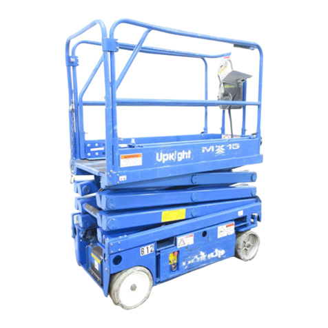
Other Upright Lifting System manuals

Upright
Upright LX31 User manual

Upright
Upright MX15 User manual

Upright
Upright X Series Guide

Upright
Upright ab62 User manual

Upright
Upright TM12 User manual

Upright
Upright ULII-25 Guide

Upright
Upright LX31 User manual

Upright
Upright LX31 User manual

Upright
Upright SL20 Series Guide

Upright
Upright MX15 User manual

Upright
Upright ab62 User manual
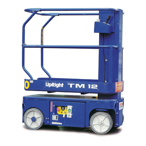
Upright
Upright SL20 Series User manual

Upright
Upright TM12 Guide
Upright
Upright TL49 User manual

Upright
Upright MX15 User manual

Upright
Upright SL-26 Guide

Upright
Upright SB47JRT User manual
Upright
Upright TM12 Guide

Upright
Upright SB60 Guide

Upright
Upright ab62 Building instructions