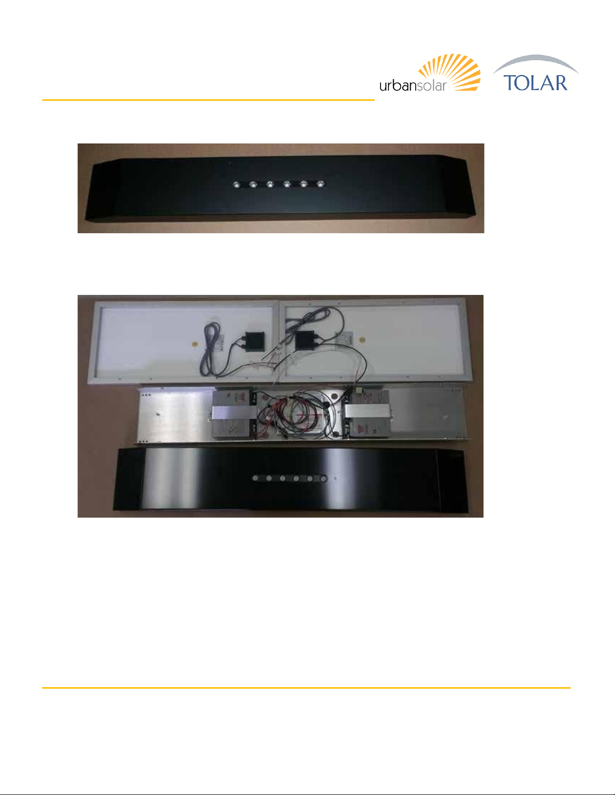
Primary System Components
The RMS80F shelter lighting system provides security lighting using state of the art LED luminaires, batteries
and solar panels, integrated with an intelligent programmable energy control module (ECM). Electrical
current generated by the solar panels flows to the ECM which regulates the charging of the battery bank and
modulates power to the LEDs. The ECM is factory programmed to provide variable calendar-based lighting
profiles to match the seasonally available solar insolation and lighting level requirements.
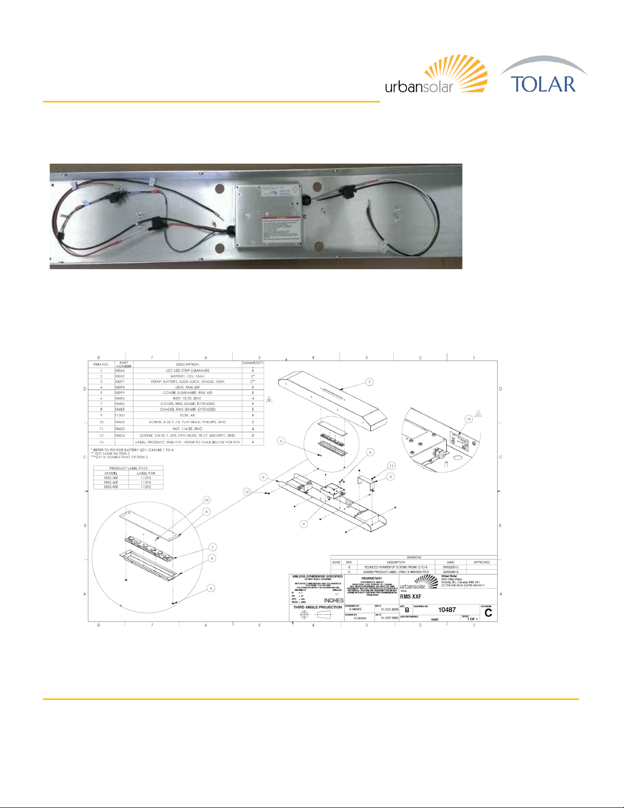
The main system components are described below:
PV Array (solar module) - The PV array typically consists of one or more 40W solar modules mounted to a
metal framework. The solar panel array size is selected to provide enough solar charging for the system to
operate dusk till dawn, at a specific brightness level, year-round at a given geographical location. The
RMS80F has 2 x 40W solar panels.
Batteries - The battery bank is composed of 2 x18 amp-hour 12 Volt packs. The batteries are sealed, lead
acid, rechargeable, and provide a minimum of 5 days autonomy (i.e. from a full charge, the system could
operate for a minimum of 5 days with absolutely no solar charging – for example during heavy snowfall).
LEDs - The LED luminaire contains high power white LEDs. The luminaires are driven well below their
maximum power rating to increase efficiency and extend the already long life.
ECM - The Energy Control Module is the central control of the lighting system. It controls battery charging
and regulates the power to the LED luminaires. The ECM also monitors the system performance to ensure
the batteries will not be damaged by overcharging and will turn off the LEDs if the battery voltage falls below
the low voltage disconnect (LVD) setting. Once the batteries have been sufficiently charged above the LVD,
the ECM will turn the LEDs back on again.
Operating Profile - The RMS80F contains a built-in programmable energy control module (ECM) that is
pre-programmed at the factory to set a calendar based operating profile to maximize the light intensity and
duration based on NASA solar insolation data for the region.