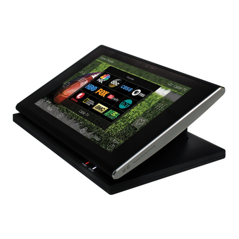
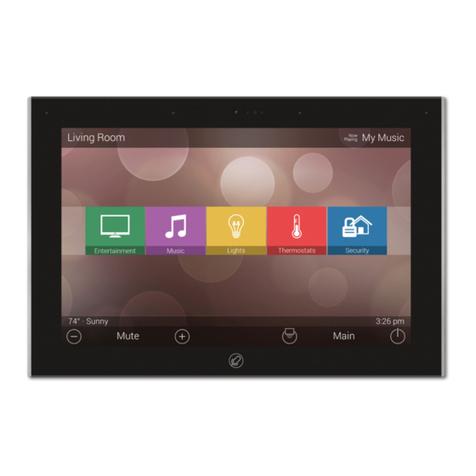
URC TKP-9600 User manual

TKP-9600
Owner’s Manual
Total Control TKP-9600
Owner’s Manual

Total Control TKP-9600
Owner’s Manual
Rev 1.0
Introducing the TKP-9600
Thank you for purchasing URC’s TKP-9600 In-Wall Net ork Keypad. Its easy and
intuitive use helps to simplify your life hile adding control of more things than you
thought possible.
Online Support
Total Control is sold direct only and must installed/program by a certied
custom integrator.
End-User Support
Visit the URC Home Page for product information, o ner’s manuals, and support
contact information.
Cont ct Support
Total Control is a URC product sold direct only. For questions or assistance contact
your Custom Installer/Programmer.
My Inst ller/Progr mmer
Technical Suppor t
Toll Free: 800-904-0800
Main: 914-835-4484
techsupport@urc-automation.com
H o u r s : 9 : 0 0 a m - 5 : 0 0 p m E S T M - F
Fe tures nd Benefits........................1
Upd ted User Experience..........1
Audio-Video Interf ce ................1
Proximity Sensor .........................2
Flexible Orient tion ....................2
TKP-9600 Inst ll tion Guidelines ....4
Unlocking the TKP-9600 .............4
Rele sing the T mper Resist nt
Lock................................................4
For New Construction.................5
For Retrofit Boxes........................6
Mounting Pl te Orient tion.......6
M in Menu N vig tion .....................7
M in Menu: View Modes ..........8
Title B r................................................9
Room’s Menu..............................10
Room Linking..............................11
Now Pl ying...............................12
Core Buttons......................................13
Shortcut Popup Menu......................14
Adding Shortcuts.......................14
Removing Shortcuts..................... 15
St tus B r ......................................16
Intercom ................................................18
N vig ting the Intercom Menu.. 20
M king C lls: Audio-Video ........21
M king C lls: Audio C lls .......... 23
M king C lls: Audio Bro dc st. 25
Do Not Disturb Mode ................... 27
Scenes Menu .......................................28
Settings Menu......................................29
Sleep Settings............................... 30
Gener l........................................... 31
Sound.............................................. 32
Brightness...................................... 32
Proximity Sensor .......................... 33
System Inform tion ...................... 34
Network .........................................35
Intercom ......................................... 36
F ctory Def ult.............................. 37
Specific tions ......................................38
Limited W rr nty St tement..............38
T ble of Contents

1
Total Control TKP-9600
Owner’s Manual
Fe tures nd Benefits
The TKP-9600 In-Wall Net ork Keypad is one of URC’s most advanced devices that is
optimized for usage ith Total Control.
Enjoy these key features:
Upd ted User Experience
This device has the capability of using URC’s Total Control soft are suite. Using this
soft are provides this device ith a modern “look and feel” giving the end-user an
improved user experience in terms of graphics, performance, and features.
Audio-Video Interf ce
Communicate ith any other URC Intercom-Enabled device in the system ith this
feature. The end-user can make Audio-Video, Audio, or Audio Broadcast calls
directly from the TKP-9600.

2
Total Control TKP-9600
Owner’s Manual
Proximity Sensor
This feature allo s the TKP-9600 to spring into action automatically. Utilizing its
proximity sensor, the keypad can detect distances from up to three (3) feet a ay.
This setting can be adjusted in the device’s Settings menu.
Flexible Orient tion
The TKP-9600 offers the ability to display the device in either portrait or landscape
mode making it the perfect keypad for almost any room. This feature can only be set
from ithin the Accelerator soft are, speak to a custom home professional prior to
installation.

3
Total Control TKP-9600
Owner’s Manual
P rt List
Included in the TKP-9600:
• 1x - TKP-9600 Net ork Keypad
• 1x - Mounting Ring
• 4x - Mounting Scre s
• 4x - Spacers
• 2x - Ribbon Spacers
TKP-9600
Sp cers
Mounting Ring
Mounting Screws
Unlock Tool
Ribbon Sp cers

4
Total Control TKP-9600
Owner’s Manual
TKP-9600 Inst ll tion Guidelines
Unlocking the TKP-9600
Prior to installing the TKP-9600 ALWAYS make sure to release the tamper lock.
Failing to do so could cause physical damage to the TKP-9600.
Rele sing the T mper Resist nt Lock
The lock is located at the top of the TKP-9600 and requires the supplied tool in
order to unlock.
To unlock the TKP-9600 use engage the tool into the lock and gently lift up. The
lock remains recessed and the TKP-9600 can be removed
Gently lift up ard

5
Total Control TKP-9600
Owner’s Manual
For New Construction
The TKP-9600 ts into any 3-gang or 2-gang box. Ho ever, there are certain
aspects of the installation that must be highlighted.
When installing a 3-gang or a 2-gang box it sits recessed in the all as seen on
the image to the right. The TKP-9600 cannot t into the mounting plate properly.
Due to the unique design of the TKP-9600, the mounting plate must be installed
ith the ribbon spacers (supplied in the box).
These strips must be placed on the backside (side facing the all) of the
mounting plate. This allo s the mounting plate to sit above the all and
properly mount the TKP-9600.
This area is recessed.
(not actual size)
Place the ribbon spacer on the top and bottom of
the mounting plate (backside). Remember to
place these on the side facing the all.

6
Total Control TKP-9600
Owner’s Manual
For Retrofit Boxes
Installing the TKP-9600 into a retrotted 3-gang or 2-gang box is easy. The
mounting plate must be installed directly onto the 3-gang/2-gang box. The frame
of the retrot box provides ample space for the TKP-9600 to mount properly on
the mounting plate.
The mounting plate is magnetic and attached to the back of the TKP-9600 easily.
Prior to installing the TKP-9600, assure the the lock is diseng ged.
Mounting Pl te Orient tion
Notice the orientation of the mounting plate. The image at the right has the
mounting plate installed on a 2-gang retrot box. When installing the mounting
plate assure that the notch is pointing do n to ard the center.
There are up arro s engraved into the mounting plate to visually assist ith the
installation. The image belo (although a replica) represents ho the mounting
plate must be installed.
This portion connects and holds the
TKP-9600 in place. It must be
positioned as seen here.

7
Total Control TKP-9600
Owner’s Manual
M in Menu N vig tion
Although specic screen design and certain options are dictated by the custom
integrator that programmed the Total Control system, the general layout
remains the same.
Actual navigation is performed via screen s ipes:
• Left Swipe: S ipe left to reveal additional Main Menu pages.
The amount of pages available on the Main Menu is dictated by
the custom integrator.
• Right Swipe: S ipe right to reveal the Scenes Menu. The Scenes
Menu contains URC Scenes that are created by the custom integrator.
Return to the Main Menu by s iping left from the Scenes Menu.
• Button T pping: On the Main Menu selecting each of these areas
provide the end-user ith control:
A. C tegory/Device Ribbon: Select a Category button to reveal the
associated sub-menu OR select a Device located here to access
that devices menu. This is dictated by the custom integrator.
B. Rooms Menu: Select the Room Name to access the Room’s
Menu. This menu allo s the end-user to control another room and
more.
C. Volume Control: Tap the minus (Vol-) to lo er the volume, plus
(Vol+) to increase the volume, and Mute to mute the volume.
D. Shortcuts: Select this button to reveal the Shortcuts Popup
menu. The end-user can add up to six (6) items on this menu.
E. M in: Select this to return to the Main Menu regardless of hat page the
device is currently on. This can be changed to return to the Scenes Menu, speak
ith the custom integrator to program the TKP-9600 this ay.
F. Room Power Off: Select this button to turn off the current room.
G. Now Pl ying: Select the No Playing button at the top to instantly jump into
that device/activity’s menu pages.
A
B
C
D E F
G

8
Total Control TKP-9600
Owner’s Manual
M in Menu: View Modes
Total Control features t o different vie modes for the
TKP- 9600. Each vie mode has its o n unique properties
that compliment the user experience.
The vie mode must be programmed from ithin the Accelerator
soft are, speak to a custom home integrator for more details.
1. Ribbon View: This is the default vie mode and it
contains up to six (6) items per page.
Ribbon View (L ndsc pe & Portr it)
2. Grid View: This vie mode contains
up to fteen (15) items per page.
Grid View (L ndsc pe & Portr it)

9
Total Control TKP-9600
Owner’s Manual
Title B r
The Title B r is al ays present regardless of hat menu and/or room the
TKP-9600 is currently using.
On the left of the Title B r, the current room the TKP-9600 is controlling is
displayed. Selecting it reveals the Rooms Menu.
At the right of the Title B r is the Now Pl ying area. This displays hich
device/activity is currently active. Selecting it returns the interface to the
device/activity’s menu for control.
The Title B r is located at the very top of the display. To access its menu,
s ipe do n as depicted on the image to the right. There are three (3)
selectable options here:
1. Close: Select this to hide the Title Bar Menu.
2. We ther Module: Select this to display the Time and Weather
Module, this feature requires the home location. This location is set
from ithin the Accelerator soft are.
3. Intercom: Select this button to display the Intercom Menu. This menu
displays all available Intercom-Enabled device (clients). Please see this
documents Audio-Video Intercom section for more details.
4. Settings: Select this button to access the TKP-9600’s Settings Menu.
The various parts of the Settings Menu are explained in detail in a later
section of this document.
Current Room Now Pl ying
1 2 3 4

10
Total Control TKP-9600
Owner’s Manual
Room’s Menu
Tap on the Room Name located on the left in the Title Bar to display the
Room’s Menu.
The Room’s Menu contains every room programmed into the system.
Specic rooms may be hidden from certain interfaces, speak to the custom
home integrator for that option.
Each room is given a Room N me and customized image to represent that
room. Additionally, the Room’s Menu can be used for controlling volume,
turning off the lights, or completely po ering off a specic room.
Here are the selectable buttons in the Room’s Menu:
1. Volume Control: Select this button to reveal the Vol +, Vol -, and
Mute icons. This button is available on any room ith audio sources.
2. Lights Off Action Comm nd: This button is programmed by the
custom integrator and can be set to turn off all the lights in a
particular room.
3. Room Off: Select this button to turn off all the devices in that
particular room. This button can only be used to turn off a room.
4. Now Pl ying: This section displays hat device/activity is currently
active in that room. Selecting this jumps the TKP-9600 to that device/
activity’s menu for control.
5. Room Linking: This feature is only available on DMS Audio device.
It is used to link DMS Zones/Areas. This means having one menu that
controls volume for multiple zones simultaneously or individually.

11
Total Control TKP-9600
Owner’s Manual
Room Linking
Remember, Room Linking can only be used by DMS Zones/Areas. The follo ing
steps take place from ithin the Room’s Menu:
1. Select the Room Link button, this displays the Room Linking Menu.
2. Select hich rooms in the system to link. Only rooms that are DMS
Zones/Areas appear on the Room Linking Menu.
3. Select the Check to conrm.
These rooms are no linked. It is possible to control volume on all of these
rooms from one menu (see belo ). Control the volume of each Linked Zone/
Area individually or simultaneously using the All Linked Rooms volume slider. 1
2
3

12
Total Control TKP-9600
Owner’s Manual
Now Pl ying
On the right hand side of the Title Bar is the No Playing area. The No
Playing area al ays dictates hat activity is currently playing in the room.
In the example at the right, Now Pl ying reads “SNP-2 P ndor ”. This
means that in the Home Theater the SNP-2 is using Pandora currently.
Tapping the No Playing area jumps the TKP-9600 to the menu for the
device in that section. In the example this mean that, once tapped, the
interface jumps to the SNP-2 device menu for control.

13
Total Control TKP-9600
Owner’s Manual
Core Buttons
These buttons are almost al ays on display. Each one of these buttons has a
specic function:
A. Volume: Used to control an active audio device.
B. Shortcut Popup: Use this to display the Shortcut Popup Menu. This
menu contains up to six (6) current room activities.
C. M in: Select this to return to the Main Menu regardless of hat menu
the interface is currently in use.
D. Room Off: Use this button to turn off the current room.
Vol- Mute Vol+
Shortcut Popup
Room Off
A D
CB

14
Total Control TKP-9600
Owner’s Manual
Shortcut Popup Menu
The Shortcut Popup Menu holds the end-user’s favorite or most
frequently used devices/activities and places them in one easy to
access location.
Adding Shortcuts
Follo these steps to add a Shortcut:
1. Locate an available button and hold it do n until the
status bar on the top of the display lls. As stated on
the bottom of the interface “Press and Hold to Add or
Remove”. A list of device/activities for that room a
presented in the Add a Shortcut Menu.
2. Select a device/activity. This adds that item to the
Shortcut Popup Menu.
1
2

15
Total Control TKP-9600
Owner’s Manual
Just tap on a Shortcut button to launch that device/activity. Remember, this menu
can only hold up to six (6) items and each item must already be a device/activity
programmed into that current room.
Removing Shortcuts
Follo these steps to remove a Shortcut:
1. From the Shortcut Popup Menu, press nd hold the Shortcut that
needs to be deleted.
2. Hold the button until the Remove Shortcut indo displays.
3. Select Remove.
1
2
3

16
Total Control TKP-9600
Owner’s Manual
St tus B r
Located above the Core Buttons, this section of the interface is almost
al ays on display. The Status Bar is designed to inform the end-user of
various customization options:
A. Met d t Inform tion: Located to the far left, options selected
from the programming soft are cycle through here. Those
selections are the follo ing:
■Room Linked St tus: Whenever the chosen room/area is
“linked” to other rooms, it is ackno ledged in this section.
■Room Al rm Clock St tus: If the current room has an Alarm
that is set to activate, the status bar displays an alarm clock
icon and the next scheduled time/day.
■V c tion Mode St tus: When Vacation Mode is activated,
the Status Bar displays “Vacation Mode On”. When inactive,
the Status Bar displays “Vacation Mode Off”.
■Sunrise: Updated at midnight every day, displays the sunrise
time for the next day.
■Sunset: Updated at midnight every day, displays the sunset
time for the next day.
■RSS We ther Alert: Based on the location entered by the
system programmer, the ords “Weather Alert” appear if an
automatic alert is received via internet.
■DMS-AV Surround Mode St tus: Displays the current sound
mode of the DMS-AV Surround Processor.
A

17
Total Control TKP-9600
Owner’s Manual
B. P ge Indic tor: The icons here represent the current page
number the interface is on. Ho ever, the icon located to the
left is the Scenes Menu icon. All icons to the right of that
represent page numbers.
C. Time: This is al ays present on the right hand side of the
interface. It serves as a quick and convenient place for the
end-user to check the time of day.
B
C

18
Total Control TKP-9600
Owner’s Manual
Intercom
The TKP-9600 has the capability of communicating across the home net ork to any
Intercom-Enabled client (interface).
There are three (3) different types of intercom calls that can be made:
1. Audio-Video: This type of call uses the camera and microphone of the
calling and receiving client to provide auditory and visual feedback.
2. Audio C ll: This type of call only uses the built in microphone of the calling
and receiving client to create an audio call over the home net ork.
1
2
Table of contents
Other URC Touchscreen manuals
Popular Touchscreen manuals by other brands

Crestron
Crestron n TPMC-12 Operation guide

Elo TouchSystems
Elo TouchSystems 1900L Specification sheet

DSC
DSC PowerSeries Neo HS2TCHP user manual

Tabler
Tabler TTV-65MH Guiding Manual

Johnson Controls
Johnson Controls Advanced Graphic Touchscreen Display Installation and operation manual

IEI Technology
IEI Technology AFL2-12A-D525 Series user manual