US Cutter MH Series User manual

VINYL CUTTER
User Manual & Assembly Instructions

2
www.uscutter.com
425.481.3555
Introduction
Heat Press Vinyl
Banners & Signage
Adhesive Wall Vinyl
Table of Contents
2Table of Contents
3Safety Precautions
4Site Selection & Preparation
5Stand Parts & Set Up
10 Blade Set Up
11 Installing the Pen Carriage
12 Get To Know Your Cutter
18 Connecting to a Computer
14 Control Panel
19 Preparing for Cutting
24 Making Your First Test Cut
26 Troubleshooting
28 Care and Maintenance
29 Warranty Statement
30 Hardware Bundles
Your new MH Vinyl Cutter and Plotter is your gateway
into a world of possibilities. From more industrial
uses like custom signage, vehicle decals, and window
graphics to hobby and art creation including wall and
glass art and garment customization.
By mastering the use of this equipment and
accompanying software, understanding which materials
to use for dierent projects, and learning a few basic
application techniques there’s not much you won’t be
able to do.
Thank you for your purchase of this new MH Cutter

3
www.uscutter.com
425.481.3555
Table of Contents
Safety Precautions
Site Selection & Preparation
Stand Parts & Set Up
Blade Set Up
Installing the Pen Carriage
Get To Know Your Cutter
Connecting to a Computer
Control Panel
Preparing for Cutting
Making Your First Test Cut
Troubleshooting
Care and Maintenance
Warranty Statement
Hardware Bundles
Safety Precautions
CAUTION IS STRONGLY ADVISED WHEN USING THIS EQUIPMENT
Device requires installation. Operation of this device requires use of
sharp blades and caution should be taken to make sure that fingers do
not get caught in moving gears during operation.
Disconnect power during assembly, service and maintenance. Vinyl
cutters are subject to static build-up. Use of anti-static devices
including mats and anti-static vinyl systems may be required in some
environments.
Vinyl cutting is a creative medium and can be an enjoyable hobby or
classroom learning experience, but this vinyl cutter is not a toy and
should not be used by children without supervision.
Except where noted, all Contents Copyright ©2015 USCutter
and may not be reproduced without express written permission.

4
www.uscutter.com
425.481.3555
Site Selection & Preparation
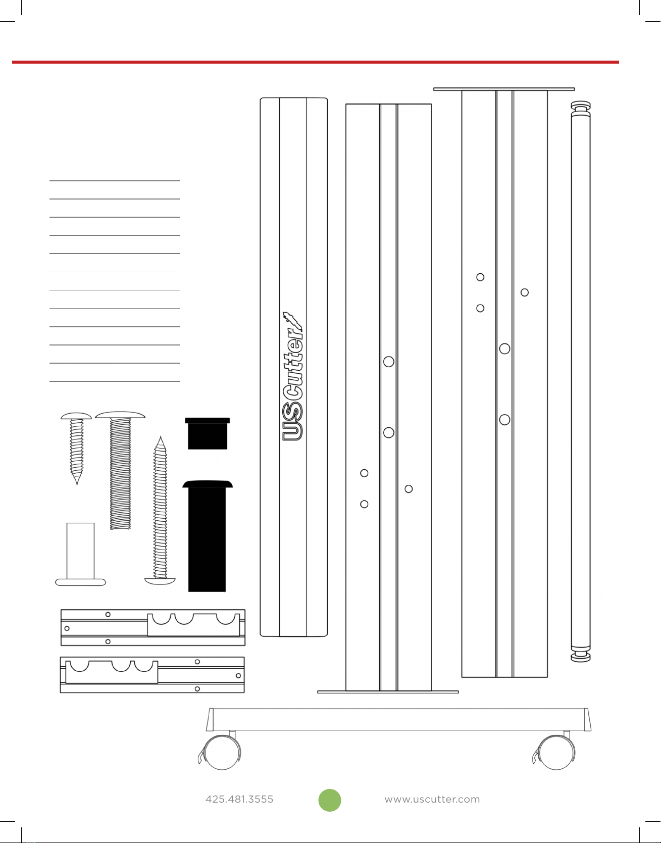
If you are setting up for the first time please take a moment to refer to the Packaging Guide to
take account of all the included components and accessories. For help with Stand Assembly,
please refer to included instructions.
The first step to setting up your cutter is finding
a good location for the machine. Consider these
factors when you are selecting a suitable place:
Stability is key. Your MH cutter is a precision cutting device and the carriage head will move
quickly back and forth across the vinyl. If it vibrates due to an uneven or unstable surface,
it will result in issues with your cut. Whether placing the machine on a stand or table top,
choose a level and stable surface.
All cutters will produce a small amount of noise while operating. Please take this into
consideration when selecting a location for your cutting purposes.
Fans located inside of the cutter can draw in outside dust from the area surrounding the
cutter. Excessive buildup of dust can cause either mechanical or electrical malfunctions.
Keeping the cutter as dust free as possible will help ensure trouble free operation. Try to find
an area for the cutter that will be free of any excessive dust and use the supplied cover when
not in use.
A 110 outlet with a grounding plug is required for operation of the vinyl cutter/plotter and you
will want internet access for our PC in order to download software and drivers required for
operation. DO NOT attempt to use the cutter when it has not been properly grounded.
You will need to have access to both the front and rear of the machine for operation and
changing out of vinyl rolls. Find a space that has adequate access and where the roll can roll
freely on the rollers or on the table top.
Place your cutter near the PC that will be used to drive content to the vinyl cutter.

5
www.uscutter.com
425.481.3555
Stand Parts & Set Up
AShort Screw
BBolt Cap
CBolt
DLong Screw
EScrew Sleeve Cap
FScrew Sleeve
GLeft Roller Arm
HRight Roller Arm
ICenter Crossbeam
JRight Column
KLeft Column
LRoller
MFoot
A
B
C
D
G
H
I
J
K
L
M
F
E
Your MH Cutter purchase may
have included a stand, if you
selected that option. If so, you’ll
want to set it up first. Please see
instructions on the following
page for assembly instructions.

6
www.uscutter.com
425.481.3555
1
B (x3) Bolt Cap
C(x3) Bolt
H(x1) Right Roller Arm
J(x1) Right Column
Attach the Right Roller Arm
to the outer side of the Right
Column
B
J
H
C
(outer side will have a curved edge and will have larger hole openings)
2
B(x3) Bolt Cap
C(x3) Bolt
G(x1) Left Roller Arm
K(x1) Left Column
Attach the Left Roller Arm
to the outer side of the Left
Column
B
K
G
C
(outer side will have a curved edge and will have larger hole openings)

7
www.uscutter.com
425.481.3555
3
D(x4) Long Screw
M(1) Foot
Attach the Foot on the right side
Assembled right side
(roller arm, column)
M
D
4
D(x4) Long Screw
M(1) Foot
Attach the Foot on the left side
Assembled left side
(roller arm, column)
M
D

8
www.uscutter.com
425.481.3555
5
A(x2) Short Screw
E(x2) Screw Sleeve Cap
F(x2) Screw Sleeve
I(x1) Center Crossbeam
Add the Center Crossbeam to the right side
(some larger models will have more than one Center Crossbeam. If your
model has 2 Crossbeams, repeat this step, attaching both to the right side)
Assembled right side
(roller arm, column, foot)
I
FAE
6
A(x2) Short Screw
E(x2) Screw Sleeve Cap
F(x2) Screw Sleeve
Add the Left Side to the completed right side
(some larger models will have more than one Center Crossbeam. If your
model has 2 Crossbeams, repeat this step, attaching the left side to both)
Assembled right side
(roller arm, column, foot)
with Center Crossbeam
F
A
E

9
www.uscutter.com
425.481.3555
8
Add the Cutter to the
completed stand
Completed stand with
rollers, MH Cutter
7
L(x2) Roller
Add the Rollers
Completed Stand
L

10
www.uscutter.com
425.481.3555
Blade Set Up
Unscrew the cap from
the Blade Carriage.
Screw the cap back
onto the Blade
Carriage.
Adjust the carriage cap until the
blade is protruding approximately
1/64th of an inch.
Adjust the Brass Ring until it
fits snug against the Cap. This
will help keep the cap in place
during operation.
Set Brass Ring on
Blade Carriage to the
fully down position.
Remove the protective
cover from a new blade.
Insert the blade into
the top of the Blade
Carriage.
1
5 76
2 3 4
Blades should be replaced every 6 months. Your blade may need
to be replaced more often if you are cutting thicker material such as
flock, glitter, or reflectives.

11
www.uscutter.com
425.481.3555
Insert the blade into
the top of the Blade
Carriage.
Installing the Pen Carriage
Loosen the locking knob
on the carriage arm.
Unscrew the top cap
from the pen carriage.
To replace the pen or spring inside of the pen carriage:
Place blade carriage
into the carriage arm.
Remove the top cap, the pen
and the spring. Replace the
pen and/or spring as necessary.
Tighten the locking knob
on the carriage arm.
Slide the spring onto the pen
from the top and insert it back
into the pen carriage.
1
1
2
2
3
3
Most new users will benefit from practice
“cutting” with the supplied pen carriage until
they are comfortable with normal operations of
the cutter and cutting software.
Your pen carriage should come assembled
and appear as it does in this image. If it does
not, please refer to the pen replacement
section below for assembly instructions.

12
www.uscutter.com
425.481.3555
Get To Know Your Cutter
Before you start cutting, you should familiarize yourself
with the cutter and its basic parts and functions.
FRONT VIEW
LEFT SIDE COVER
FEED ROLLERS
PINCH ROLLERS
CARRIAGE ARM CONTROL PANEL
POSITIONING BUTTON
RIGHT SIDE COVER
CONTROL PANEL Used to provide input directly to the cutter. Covered in
detail in the “Control Panel” section of this manual.
CARRIAGE ARM Holds the blade (or pen) carriage.
PINCH ROLLERS Holds the media tightly to the feed roller below.
FEED ROLLERS Positions the cutting material during operation.
POSITIONING
BUTTON
Used by the cutter to determine the location of the carriage
arm.
LEFT SIDE COVER Contains the power cable port, power switch, and fuse
cartridge for the cutter.
RIGHT SIDE COVER Contains the USB and serial cable ports for the cutter.

13
www.uscutter.com
425.481.3555
CONTROL PANEL Used to provide input directly to the cutter. Covered in
detail in the “Control Panel” section of this manual.
CARRIAGE ARM Holds the blade (or pen) carriage.
PINCH ROLLERS Holds the media tightly to the feed roller below.
FEED ROLLERS Positions the cutting material during operation.
POSITIONING
BUTTON
Used by the cutter to determine the location of the carriage
arm.
LEFT SIDE COVER Contains the power cable port, power switch, and fuse
cartridge for the cutter.
RIGHT SIDE COVER Contains the USB and serial cable ports for the cutter.
CARRIAGE SLOT
LOCKING KNOB
CARRIAGE SLOT Holds the blade carriage
in place.
LOCKING KNOB
Allows access to the
blade/pen carriage slots
for exchanging/replacing
carriages.
USB CABLE PORT
USB CABLE PORT
Used to connect a USB
cable from the cutter to a
computer.
SERIAL (COM)
CABLE PORT
Used to connect a serial
cable from the cutter to a
computer.
RIGHT SIDE VIEW
POWER SWITCH
FUSE CARTRIDGE
POWER CABLE PORT
POWER CABLE
PORT
Used to connect a power
cable from the cutter
to a wall outlet or surge
protector.
POWER SWITCH
Main power switch for
turning the power of the
cutter on (1) or o (0).
FUSE CARTRIDGE Allows access to the fuse
inside of the cutter.
LEFT SIDE VIEW
SERIAL (COM) CABLE PORT

14
www.uscutter.com
425.481.3555
Control Panel
MAIN SCREEN
The main screen of the cutter allows you to set the main settings of the cutter including the cutting speed and cutting
force options. It also allows you to cut a test pattern or check the amount of force that is currently set.
RESET BUTTON Resets by stopping the cutter, and setting the origin of the carriage arm to its
right most position.
OFFLINE/PAUSE BUTTON Accesses the Oine/Pause mode.
SETUP BUTTON Accesses the Setup mode.
TEST BUTTON
Will cut a small test shape so that the current force and speed settings of
the cutter can be tested. You can use this to determine the proper cutting
speed and force settings needed for dierent materials without wasting large
amounts of material from cutting full designs.
ORIGIN BUTTON
Used to test z-axis functionality (by dropping the blade down if the carriage
is functioning properly) or to set a new origin point when the machine is in its
oine mode.
V+ / V- BUTTONS
Adjusts the cutting speed. A cutting speed of 300 mm/s is a reasonable
default speed that can be used for most cuts. When working with smaller and
more detailed images, a slower speed may be required. When working with
larger and less detailed images, a higher speed can be used to shorten the
operation time.
F+ / F- BUTTONS
Adjusts the cutting force. A cutting force of 100g is a good general starting
place to work from when trying to determine the force needed for a specific
material. All cuttable materials will dier in the amount of force needed so
proper testing should always be made to determine the amount of force to
use. The amount of force used should be enough to fully penetrate the material
to be cut while not enough to cut through the backing material.

15
www.uscutter.com
425.481.3555
OFFLINE/PAUSE SCREEN
Oine mode is used to reposition the cutting material and blade so that a new starting position can be set
for the next design. Oine mode can also be accessed while the cutter is in operation and will pause the
current cutting process. Although changes can be made to the material and blade positions if Oine/Pause mode is
accessed during cutting, making changes to either setting is not normally recommended.
RESET BUTTON Resets by stopping the cutter, and setting the origin of the carriage arm to
its right most position.
OFFLINE/PAUSE BUTTON
Ignores any changes that have been made to the material or blade positions
and exits Oine/Pause mode, returning the cutter to the main screen.
Resumes any cutting that was taking place when Oine/Pause mode was
entered.
SETUP BUTTON Has no function in this mode.
TEST BUTTON
Accepts any changes that have been made to the material or blade
positions and exits Oine/Pause mode returning the cutter to the main
screen. Resumes any cutting that was taking place when Oine/Pause
mode was entered from the new blade/material positions.
ORIGIN BUTTON
Accepts any changes that have been made to the material or blade
positions and exits Oine/Pause mode returning the cutter to the main
screen. Resumes any cutting that was taking place when Oine/Pause
mode was entered from the new blade/material positions.
V+ / V- BUTTONS
Repositions the material by moving the feed rollers. After movements
are made you can confirm the changes by pressing the TEST or ORIGIN
buttons or cancel by pressing the OFFLINE/PAUSE button.
F+ / F- BUTTONS
Repositions the blade by moving the carriage arm. After movements are
made you can confirm the changes by pressing the TEST or ORIGIN buttons
or cancel by pressing the OFFLINE/PAUSE button.

16
www.uscutter.com
425.481.3555
SETUP SCREEN
The Setup screen allows you to adjust some of the more technical settings of the cutter.
For most users, these settings should not be changed.
RESET BUTTON Resets by stopping the cutter, and setting the origin of the carriage arm
to its right most position.
OFFLINE/PAUSE BUTTON Has no function in this mode.
SETUP BUTTON Exits Setup mode and returns to the main screen.
TEST BUTTON Has no function in this mode.
ORIGIN BUTTON Has no function in this mode.
V+ / V- BUTTONS Adjusts the Up Speed of the cutter.
F+ / F- BUTTONS Adjusts the Baud Rate of the cutter.

17
www.uscutter.com
425.481.3555
Cut & Place Vinyl Like A Pro
www.uscutter.com
425.481.3555
GET EVERYTHING FOR YOUR
VINYL CUTTING NEEDS
Digital Printed
Graphics
Indoor Wall
Vinyl
Heat Press
Outdoor
Signage
Stencils &
Masks
You also need the right
media, blade, and
application tape to
ensure a professional job.
A good VINYL CUTTER
is just the start...
Main Tape
GFX-341
45°
Blade
45°
Blade
Oracal 3951 & 3651
HP Gloss & Matte
Glass Application
45°
Blade
Oracal 8300, 8500,
8510, & 8800
Main Tape
GXF-775 or
R-Tape AT65
Main Tape
GXP750 or
Oratape HT55
Oracal 631 or
GreenStar Wall Vinyl
30° Blade
(general)
60° Blade
(glitter/flock)
EasyWeed
(standard fabrics)
EasyWeed Extra
(nylons/water resistant)
R-Tape
4076RLA 60° Blade
Anchor BlastLite
Oramask
GreenStar
Layflat Classic or
Main Tape
GXF-775
45° Blade
(general)
60° Blade
(reflective)
Oracal 651 or GreenStar
Intermediate (calendered)
for short term
Oracal 751 or 951 (cast)
for long term
CUT & PLACE VINYL LIKE A PRO
45°
MEDIA
CARRIER
MEDIA
CARRIER
MEDIA
CARRIER
60
MEDIA
CARRIER
MEDIA
CARRIER
MEDIA
CARRIER
MEDIA
CARRIER
60
The “workhorse blade” good
for most vinyl materials.
30°
MEDIA
CARRIER
MEDIA
CARRIER
MEDIA
CARRIER
MEDIA
CARRIER
60
60°
MEDIA
MEDIA
CARRIER
MEDIA
CARRIER
MEDIA
CARRIER
60
For use on thicker materials
and for highly detailed cuts.
Use sparingly to preserve
sharpness.
Best for thin materials
such as heat press vinyl.
Your blade depth should be set so
that the tip of the blade protrudes
about the distance of the width of
a credit card from the opening of
the blade holder. Test for the proper
depth setting by holding the blade
holder and manually trying to cut
through two sheets of paper. You
should only be able to cut
through the top sheet.

18
www.uscutter.com
425.481.3555
Connecting The Cutter To A Computer
Attach the power cord to the cutter and then
plug in the unit and turn on the power.
If using the Serial Cable to connect
your cutter to a computer:
If using the USB Cable to connect
your cutter to a computer:
If you are using a Serial Cable to connect your cutter to a computer then
no further setup is necessary. Simply connect one end of the cable to
the cutter and the other end to a computer and setup is complete. If
you have more than one serial connection on your computer or you are
experiencing communication issues between your cutter and computer
then you may wish to verify that the correct COM port is being used in
your software setup, but for most users the COM port will be COM1.
Most current versions of Windows and the current VinylMaster release
already have drivers pre-loaded. If, howver you find you still need to install
drivers go to www.uscuttersupport.com/mh-support-page and select the
driver that supports your older Windows version.
INSTALLING VINYL MASTER SOFTWARE
Your MH Vinyl Cutter comes bundled with VinylMaster Cut software, an easy to use software with the tools to
help you take your projects from concept to a ready to cut computer image file.
You can download and install the VinylMaster Cut software at www.uscutter.com/download, and you will need
the key code (sometimes referred to as a PSN) packaged with this cutter to activate the software.
Training for VinylMaster is all done via short videos accessed through the software.

19
www.uscutter.com
425.481.3555
If using the Serial Cable to connect
your cutter to a computer:
If using the USB Cable to connect
your cutter to a computer:
Preparing For Cutting
Place the roll on top of the stand rollers.
Release the pinch rollers release levers.
If you are going to cut from a scrap or single sheet instead of a roll, then skip the
next step on placing a vinyl roll. All other steps will be the same.
1
2
For heat press vinyl, please flip the roll.

20
www.uscutter.com
425.481.3555
Feed the vinyl underneath the pinch rollers
(if working from a single sheet instead of
a roll, the vinyl can also be feed from the
front).
Adjust the pinch rollers so there is one roller located on each side of the
vinyl (and, on models with 3 or more rollers, one roller near the center).
Avoid lowering a pinch roller to the gap between the two feed rollers.
3
4
This manual suits for next models
3
Table of contents
Other US Cutter Cutter manuals

US Cutter
US Cutter SC User manual

US Cutter
US Cutter SC2 User manual

US Cutter
US Cutter LaserPoint User manual

US Cutter
US Cutter Laserpoint II User manual

US Cutter
US Cutter LaserPoint3 User manual

US Cutter
US Cutter MH-721 User manual

US Cutter
US Cutter Titan User manual

US Cutter
US Cutter Copam User manual
Popular Cutter manuals by other brands

Mejix
Mejix DC 580 Original manual translation

CARL
CARL DC-200N instruction manual

VersaLASER
VersaLASER VLS3.60 SAFETY, INSTALLATION, OPERATION AND MAINTENANCE INSTRUCTIONS

Ioline
Ioline SmarTrac 100 Series quick start guide

ryan
ryan 544853G Operator's & parts manual

CountyLine
CountyLine RBRC402CL Operation and assembly manual