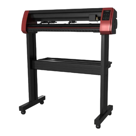
US Cutter LaserPoint3 User manual

User Manual & Assembly Instructions

www.uscutter.com
425.481.3555
2
IMPORTANT SAFETY INSTRUCTIONS
Do not place any magnetic objects in the vicinity of the cutting head; otherwise uni-
form contact Force is not ensured.
Do not remove the connection cable to the computer while plotting is in progress.
Do not reach into the unit with your hands when the power is connected.
Never open the housing or attempt to modify the unit unless instructed to do so by a
qualified technician.
Ensure that liquids and metal objects do not get into the cutter.
Ensure that the wall socket used is grounded and protected with a ground fault
switch.
Ensure that the connected voltage (110V) does not deviate by more than ±10%.
Otherwise install a voltage stabilizer.
Never reach into the unit in the vicinity of the blade holder during the cutting opera-
tion!
Discontinue any printing jobs in progress before readjusting the blade holder!
Always ensure that the vinyl cutter is out of reach of children during operation and
never leave the unit or individual parts of it switched on without supervision.
Do not touch the tip of the sliding blade to avoid injury.
Always place the unit on a stable base to prevent it from falling down.
Do not operate the unit during thunderstorms; it can be damaged or destroyed by
lightning.

www.uscutter.com
425.481.3555
3
Table of Contents
Thank you for purchasing the Laserpoint3 vinyl cutter. Please read this manual
completely and keep it in a safe place for future reference.
For Accessories, Supplies, and replacement parts please visit our website at www.uscutter.com
651
1 Intro
4Where to use and store your vinyl cutter
5What’s in the box
6 Assembling the stand
10 Getting to know your cutter
12 Connecting to a computer
14 Setting up media
22 Making your first test cut
21 Control Panel
26 Troubleshooting
28 Maintenance
23
29 Cut and place vinyl like a pro
20 Blade set up
24 Contour cutting

www.uscutter.com
425.481.3555
4
Locations for use and storage
Where to use and store the vinyl Cutter
Location, Location, Location! It’s not just important for real estate. Where your vinyl
cutter “lives” in your home or business is a vitally important element of your success.
You need access to a 110 volt grounded electrical outlet. That’s the
standard household kind with three holes, not two. Be safe... don’t
plug your cutter into an already over-crowded powerstrip or system
of extension cords.
Dust and dirt will limit the useful life of your cutter. If you use it in a
dusty or dirty environment the cooling fans will suck in the dust and
it will get inside the machine and gum up the works.
Operate on a stable surface. A solid flat surface is needed for your
vinyl cutter to do its best work. If it wobbles or vibrates during oper-
ation your cut is not going to be as sharp and clean as it could be.
Access is important. The Laserpoint3 cutter is a large machine, but
it doesn’t belong in the corner during use. You’ll need to access the
front and back of the cutter to operate it and change the vinyl rolls.
1
2
3
4
5
6
There will be some noise when the cutter is in use. Take that into
account when you locate your vinyl cutting headquarters.
Position the cutter near enough to your computer to be able to attach it
via USB cable or 9-pin serial cable. Internet access will be necessary for
downloading drivers and software.

www.uscutter.com
425.481.3555
5
Stand Items:
What’s in the box
F
E
DB
C
A
A:
B:
C:
D:
E:
F:
G:
H:
I:
J:
K:
L:
G
Before starting work, please check whether
the following items are all present.
If any parts seem to be missing from your package
please contact support @1-888-975-2047
I
H
JK
Foot x2
Catch Basket x1
Catch Bars x2
Cross Brace x1
Mount Bracket x2
Leg x2
Roller Bars x2
Roller Bracket x2
Roller Holders x2
Basket Bracket x2
Casters x4
Screw Guide x1
L
OR
Only one of these SW download cards
Power cord Cutter
Blade box Blade holder Pen tool Serial cable USB cable

www.uscutter.com
425.481.3555
6
Before you begin:
Read the assembly instructions from beginning to end. Give yourself plenty
of time. Gather the tools you’ll need that aren’t inluded in the box:
1. A Phillips head screwdriver.
Step 1.
Attach the feet (A) to the legs (F).
This is the foot:
This is the leg:
Attach the foot to the leg with four #1 screws.
Notice there are more than four holes on the foot.
Line up the foot and the leg so that the four holes in the leg that look like this
line up with the four holes on the foot.
Assembling the stand
#1 #2 #3
K
A
K
Attach the wheels (K). Simply screw
them into the bottom of the stand
feet(A)., two wheels for each foot. You
can do this before or after attaching the
foot to the leg.

www.uscutter.com
425.481.3555
7
Assembling the stand
Which end of the leg do I attach the foot?
Good question. See those two holes that are further toward one end of the
leg? That’s where your cross piece is going to attach and hold the two legs
together. Attach the foot to the other end.
Also, note the use of the tubular screw guide and how to place it in the leg
holes when attaching the leg to the cross beam. If you cannot find your screw
guide, you can use a large drinking straw or thick milkshake straw instead.
One side is rounded and the other has sharp corners? Which side
should face out?
The rounded edge side should face out. If you look closely at the holes
you will see that one side is biger than the other. The small holes will
attach the cross piece and you’ll screw them in through the larger hole.
Attach the foot to the leg with four #1 screws using the Phillips screw-
driver. Repeat with the other leg and foot making sure the rounded
edge faces out and the holes for the cross piece are close to the top.
Install foot here
Face out Face in
Screw Guide
(place in leg)
L

www.uscutter.com
425.481.3555
8
Assembling the stand
Step 2.
Attach the cross beam (D) to the legs (F) with 8 #1 screws (4 for each leg).
This is where making use of a chair or bench to
hold the cross piece in place while you attach the
first leg will come in handy.
We’ve got the rounded edge and sharp edge
situation again? Which way do I orient the
crossbeam?
It actually doesn’t matter, but most people consider placing the
rounded edge facing the front more aesthetically pleasing.
Here you will need to use the tubular screw guide (L) to keep
the #1 screws from dropping down the leg when you attach the
cross beam to the leg.
Step 3.
Now let’s mount the roller brackets (H) to the legs (F). They’ll attach at
the crosspiece and will create a place for the rollers to sit.
NOTE: If your roller brackets arrived in four pieces instead of two, simply attach the
black plastic roller holders (I) to the metal brackets (H) with those extra six #3 screws
(the smallest ones).
TIP: You can mount the black plastic roller holders with the twin slots either closer or
further from the cutter depending on size of rolls you use most often. Just flip the roller
holder and leave out the small screw from the center position.
Use 4 #2 screws (2 on each side) to attach
the roller brackets to the stand legs. The
metal brackets have a “lip” which the
roller guide sits on. When you attach the
bracket, make sure the lip faces inward so
that the brackets are completely inside the
span of the legs
H
F
F
D
L

www.uscutter.com
425.481.3555
9
Assembling the stand
Step 4.
Attach the mounting brackets (E) to the top of the legs (F). This is where
you will mount your Laserpoint3 Cutter.
Use 8 #1 screws (4 on each bracket) to at-
tach the mounting brackets to the top of
the legs. The brackets have a staircase-like
shape. you will screw the lower “stair” to
the stand leg and will attach your Cutter to
the upper “stair” in a later step.
Step 5.
Step 7.
In order to mount the cutter to the
mounting brackets (E) on the stand, you first
need to remove the feet from your cutter.
With your cutter sitting on the mounting
bracket, re-attach the feet so that they
secure the cutter to the stand.
Alternatively you can remove the feet and
just use screws and washers to secure the
cutter to the stand.
Some cutters will have an optional mounting strategy that
allows attachment of the cutter via two thumbscrews that
screw into the bottom of the cutter.
The mounting bracket may be slighly dierent for these models.
F
E
Attach the front catchbasket bracket to the
leg using 4 #2 screws (2 on each bracket).
Thread the catch basket poles through the
catchbasket and position the catch basket
in the front and back grooves of the basket
brackets. Place roller bars in position.
If roller bars seem too short, brackets in
Step3 need to swap sides.
E
Step 6.

www.uscutter.com
425.481.3555
10
Getting to know your cutter
Before you start cutting, you should familiarize yourself
with the cutter along with its basic parts and functions.
CONTROL PANEL Used to provide input directly to the cutter. Covered in
detail in the “Control Panel” section of this manual.
CARRIAGE ARM Holds the blade (or pen) carriage.
PINCH ROLLERS Holds the media tightly to the feed roller below.
FEED ROLLERS Positions the cutting material during operation.
POSITIONING LASER Used by the cutter to determine the location of cut contours
LEFT SIDE COVER Contains the power cable port, power switch, and fuse
cartridge for the cutter.
RIGHT SIDE COVER Contains the USB and serial cable ports for the cutter.
FEED ROLLERS
LEFT SIDE COVER
PINCH ROLLERS CONTROL PANEL
RIGHT SIDE COVER
POSITIONING LASER
CARRIAGE ARM
CARRIAGE

www.uscutter.com
425.481.3555
11
Get to know your cutter
CARRIAGE SLOT
LOCKING KNOB
CARRIAGE SLOT Holds the blade carriage
in place.
LOCKING KNOB
Allows access to the
blade/pen carriage slots
for exchanging/replacing
carriages.
USB CABLE PORT
RIGHT SIDE COVER
USB CABLE PORT
Used to connect a USB
cable from the cutter to
a computer. (Best option)
SERIAL (COM)
CABLE PORT
Used to connect a serial
cable from the cutter to a
computer.
NOTE: Only one connection to the PC
is needed, either USB or serial. It is
recommended that you use USB.
RIGHT SIDE VIEW
POWER SWITCH
FUSE HOLDER SLOT
POWER CABLE PORT
POWER CABLE
PORT
Used to connect a power
cable from the cutter
to a wall outlet or surge
protector.
POWER SWITCH
Main power switch for
turning the power of the
cutter on (1) or o (0).
FUSE HOLDER
SLOT
Allows access to the fuse
inside of the cutter.
LEFT SIDE VIEW
SERIAL (COM) CABLE PORT

www.uscutter.com
425.481.3555
12
Connecting the cutter to a computer
Attach the power cord to the cutter and then
plug in the unit and turn on the power.
If using the Serial Cable to connect your cutter to a computer:
If using the USB Cable to connect your cutter to a computer:
(USB is the recommeded connection method)
If you are using a Serial Cable to connect your cutter to a computer then
no further setup is necessary. Simply connect one end of the cable to
the cutter and the other end to a computer and setup is complete. If
you have more than one serial connection on your computer or you are
experiencing communication issues between your cutter and computer
then you may wish to verify that the correct COM port is being used in
your software setup, but for most users the COM port will be COM1.
In most cases, all needed PC drivers will be preloaded in VinylMaster.
If you need to download and install drivers for the USB connection to
work properly go to www.uscuttersupport.com and select the driver that
supports your Windows version.
INSTALLING VINYL MASTER SOFTWARE (If purchased)
Your Vinyl Cutter may have optionally come bundled with VinylMaster Cut
software which is Windows compatible. Software is download only (no CD).
Download VinylMaster Cut software at www.uscutter.com/download
You will need the key code packaged with this cutter to activate the
software. You may need to download drivers to support your operating
system. Drivers are available at http://support.uscutter.com
Training for VinylMaster is all done via short videos accessed through the
software. To access the videos, click on the SUPPORT link in VinylMaster,
then further on HELP TOPICS.
KEY CODE
NOTE: Only one connection method (USB or Serial) is needed. USB is recommended.

www.uscutter.com
425.481.3555
13
Installing software
INSTALLING SURE CUTS A LOT SOFTWARE (If purchased)
Your Vinyl Cutter may have optionally been bundled with SURE CUTS A LOT sw.
Software is download only (no CD). If purchased, you should have received a card
with a download code, which will allow you to download and activate the software.
Download SURE CUTS A LOT sw: http://www.craftedge.com/redeem/scal4pro
Scratch away the covered area on the back of the card to reveal your download
code. Note that the download code on the scratch card is dierent from the Product
Serial Number which you will receive via email at download.
Click on the Cutter Icon to open the
Cut Settings menu. The General tab
should now show Laserpoint3 as the
selected cutter.
Set the connection to USB and the
port to auto-detect. (assuming you are
using a USB connection).
To add Laserpoint3 in Sure
Cuts A Lot software, select
Cutter option from the top
menu,
Follow the pull down to My
Cutter, Manage Cutters and
select USCutter from the
bottom of the pull down list.
Within Manage My Cutters menu, select
Company=USCutter and Model=Laserpoint3.
Click on the Add to List button so That
USCutter appears in the list on the left.
Laserpoint3 will appear as a pull-down selection
in the Cut Settings menu as seen in the
following frame

www.uscutter.com
425.481.3555
14
Setting up Media
Feed the vinyl underneath the pinch rollers
(if working from a single sheet instead of
a roll, the vinyl can also be feed from the
front).
3
Release the pinch rollers release levers.
2
Place the roll on top of the stand rollers.
1

www.uscutter.com
425.481.3555
15
Setting up Media
Adjust the pinch rollers so there is one roller located
on each side of the vinyl (and, on models with 3
or more rollers, one roller near the center). Avoid
lowering a pinch roller to the gap between the two
feed rollers.
4
Leave a gap of between 1/
2”-1
1/
2” from the
edge of the roller and the edge of the vinyl
on both sides.
Engage the Pinch Rollers by pushing down
on the Pinch Roller Release Levers.
5
If the cutter is not already on, turn it on now.
6

www.uscutter.com
425.481.3555
16
Under the File
pull down
menu select
Vinyl Spooler
When in the
Spooler select
Connections tab
Installing VinylMaster drivers

www.uscutter.com
425.481.3555
17
Click ADD, and
then select maker
USCutter from pull
down menu
Select Laserpoint3
cutter from the pull
down menu
Installing VinylMaster drivers

www.uscutter.com
425.481.3555
18
Verify that Direct
COM Port appears
and then select
Auto Detect
Follow the PC
prompts to turn
o/on and click
Next
Installing VinylMaster drivers
Tip: Disconnecting
and reconnecting the
USB cable at the PC
is often more reliable
than power cycling

www.uscutter.com
425.481.3555
19
The latest release of Vinyl Master Cut has a new installation wizard that may already have installed the
correct cutter driver for you. If your cutter driver is already installed and functional via the wizard, you
may use the above instructions whenever you wish to add a new cutter model.
Newer versions of Vinyl Master Cut also have extensive help menus and context sensitive videos that will
help train you and help guide you through any software issues you may experience.
You can find additonal information about VinylMaster setup and configuration at:
https://www.uscutter.com/VinylMaster-Support
You should see
a large Green
checkmark when
your cutter has
been detected.
Installing VinylMaster drivers

www.uscutter.com
425.481.3555
20
Blade Set Up
Use 45 degree blade for
most common uses
Use 60 degree blade for
thicker materials
Set blade depth to cut only
the material not the backer
BLADE SETUP
TIPS FOR GETTING OPTIMAL RESULTS
• Use a short blade depth. You only need to extend the blade 1/2 the thickness of a credit card. New users tend to ex-
pose too much blade. The idea is to cut through only the top layer of the vinyl and to leave the backing layer with only
minimal scratches. This allows you to weed the top layer o the backing easily. If corners or small detail do not cut all the
way through, consider increasing the force before extending the blade depth. If you can feel cut lines on the backer un-
derneatth the vinyl, blade depth should be reduced. You only need to extend the blade depth or use the 60 degree (blue
tip) blade for thicker materials.
• Set a safe and reliable speed. A good starting value for speed is 300. Once you have accumulated experience with the
material you are cutting and production time becomes a factor, you can look to increase the speed. Also, intricate jobs
typically require lower speeds.
• Set the correct force. A good starting value for force is 70, then you can adjust force up or down depending on how
thick/dense the material is to be cut. With test material in place, use the the Test Cut icon on the cutter’s main screen to
cut a small square in your test material to see that it cuts all the way through and can be weeded easily
• Align the pinch rollers so that they are under the guide arrows. The pinch rollers must align with the gritted sections on
the bottom roller.
• A cutting mat (optional, purchased separately) can be used when cutting materials that do not have their own back-
ing. Place your material on the cutting mat so that the pinch rollers roll on the mat, not the material. Move unused pinch
rollers out of the way so they don’t touch the parts of the material being cut. Use a brayer roller to flatten your material
on the sticky part of the cutting mat or tape the edges of thicker materials to the cutting mat. For wider jobs, it some-
times cannot be avoided and the pinch rollers will need to roll over areas of the material being cut. Typically this is not a
problem.
• When cutting long pieces of material it is important to carefully position the material so that it is completely straight
and doesn’t drift to one side when cutting.
This manual suits for next models
1
Table of contents
Other US Cutter Cutter manuals

US Cutter
US Cutter MH-721 User manual

US Cutter
US Cutter Titan User manual

US Cutter
US Cutter LaserPoint User manual

US Cutter
US Cutter SC2 User manual

US Cutter
US Cutter Laserpoint II User manual
US Cutter
US Cutter SC User manual

US Cutter
US Cutter Copam User manual
US Cutter
US Cutter MH Series User manual