8
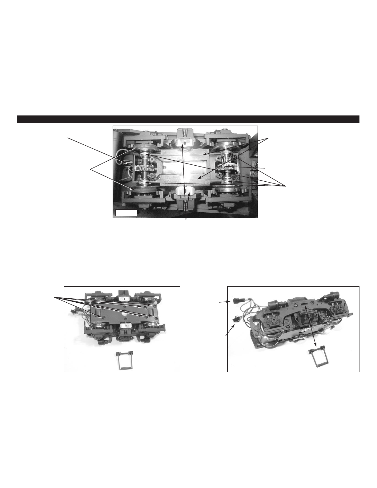
ASSEMBLY AND DISASSEMBLY INSTRUCTIONS
SERVICING
This Diesel locomotive is built with pride by USA Trains and is covered
by a limited warranty. (See limited warranty terms). Please follow these
instructions carefully before sending your locomotive for service:
1. All main handrails must be removed and kept by the customer.
2. The locomotive must be packed in the original blue/red box with
the original styrofoam inserts and then packed in the original proper
shipping carton so it is well protected in shipment. The package must
be fully insured and prepaid. USA Trains is not responsible for damage
or loss during shipment.
3. Include a note explaining the problem and servicing you need per-
formed. Be sure to include your name, street address, (NO P.O. BOXES
PLEASE) City, State, Country (if outside U.S.A) and zip code along with
a daytime phone number including area code. If the locomotive serv-
ice is not covered by warranty, a reasonable service fee will be
charged. For any locomotives to be returned outside the continental
U.S.A., please include $25.00 U.S. currency to cover return postage.
Any locomotives returned in the continental U.S.A. will be pre-paid by
USA Trains.
4. Ship your item to: USA TRAINS
662 CROSS STREET
MALDEN, MA. 02148
LIMITED ONE YEAR WARRANTY
This USA Trains locomotive is warranted for one year from the date of
purchase against defects in material or workmanship. We will repair or
replace (at our option) the defective part without charge for parts or
labor within one year of the original date of purchase provided the
warranty registration card has been received by USA Trains. This war-
ranty does not cover items that have been abused or damaged by
careless handling or improper operation such as a train derailment,
modification or repair by non-factory technicians. Parts that “wear
out” due to excessive use are also not covered under warranty. USA
Trains reserves the right to to determine “excessive use”. Transportation
costs incurred by the customer are not covered under this warranty.
USA TRAINS • PO BOX 100 • MALDEN, MA 02148, USA
www.usatrains.com