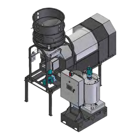
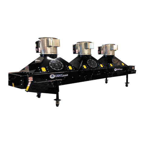
USC Surge Hopper User manual

SURGE AND WEIGH HOPPERS
2320 124th Road Sabetha, KS 66534 Phone:(785) 431-7900 www.uscllc.com
Document: TD-09-06-1013 Revision: E
OPERATOR’S MANUAL
Effective Date: 01-2021

Page 2
WEIGH HOPPERS & SURGE HOPPERS
Introduction
Thank you for choosing USC LLC for your equipment needs. We appreciate your
business and will work diligently to ensure that you are satisfied with your choice.
OVERVIEW
The purpose of this manual is to provide you with the basic information needed to
operate and maintain the Weigh Hopper and Surge Hopper. It does not hold USC LLC
liable for any accidents or injuries that may occur.
The technical information provided in this document is based on extensive testing
under controlled conditions at the USC research and development facility.
This information is given without guarantee as the conditions of operation and storage
of the equipment are beyond our control. Variables such as temperature, humidity,
viscosity of chemical products and changes in seed size or variety may all effect
the accuracy of application and seed coverage. Periodically check the equipment
calibration while treating and make adjustments as required. This will insure the
optimum seed coverage.
Serial
Number
RECEIVING YOUR EQUIPMENT
As soon as the equipment is received, it should be carefully inspected to make certain
that it has sustained no damage during shipment and that all items listed on the
packing list are accounted for. If there is any damage or shortages, the purchaser
must immediately notify USC LLC. Ownership passes to purchaser when the unit
leaves the USC LLC. premises. The purchaser is responsible for unloading and
mounting all components of the equipment.
Document the serial number of the machine for future reference. The serialization
label is located on the angle bracket welded to the hopper cone
SERIAL NUMBER:__________________________________

Page 3
WEIGH HOPPERS & SURGE HOPPERS
Section Contents Page #
Section A Safety Instructions ................................................................4
Section B Installation ...........................................................................10
Surge Hopper ........................................................................10
Surge Hopper with K-Valve ...................................................11
Weigh Hopper .......................................................................12
Section C Mechanical Operation .........................................................19
Surge Hopper Overview ........................................................19
Surge Hopper with K-Valve Overview....................................20
Weigh Hopper Overview........................................................21
Section D Electrical Operation.............................................................22
Changing Vibrator Output settings .........................................22
Section E Troubleshooting ..................................................................23
Section F Maintenance.........................................................................24
Section G Storage.................................................................................27
Section H Limited Warranty .................................................................28
Table of Contents

Page 4
WEIGH HOPPERS & SURGE HOPPERS
Safety Instructions
Section
A
Every year accidents in the work place maim, kill and injure people. Although it may
be impossible to prevent all accidents, with the right combination of training, operating
practices, safety devices, and operator vigilance, the number of accidents can be
significantly reduced. The purpose of this section is to educate equipment users
about hazards, unsafe practices, and recommended hazard avoidance techniques.
SAFETY WORDS AND SYMBOLS
It is very important that operators and maintenance personnel understand the words
and symbols that are used to communicate safety information. Safety words, their
meaning and format, have been standardized for U.S. manufacturers and published by
the American National Standards Institute (ANSI). The European Community (E.C.)
has adopted a different format based on the International Standards Organization
(I.S.O.) and applicable machinery directives. Both formats are presented below.
Graphic symbols are not standardized, but most manufacturers will use some variation
of the ones seen in this manual.
Indicates an imminently hazardous situation which, if not
avoided, will result in death or serious injury.
Indicates a potentially hazardous situation which, if not avoided,
could result in death or serious injury.
Indicates a potentially hazardous situation which, if not avoided,
may result in minor or moderate injury and/or property damage.
Provides additional information that the operator needs to be
aware of to avoid a potentially hazardous situation.
SAFETY
INSTRUCTIONS

Page 5
WEIGH HOPPERS & SURGE HOPPERS
Mandatory Lockout Power Symbol. Disconnect, lockout and
tagout electrical and other energy sources before inspecting,
cleaning or performing maintenance on this panel.
International Safety Alert Symbol. The exclamation point (!)
surrounded by a yellow triangle indicates that an injury hazard
exists. However, it does not indicate the seriousness of potential
injury. The exclamation point (!) is also used with the DANGER,
WARNING and CAUTION symbols so the potential injury is
indicated.
Electrocution Hazard Symbol. This symbol indicates that an
electrocution hazard exists. Serious injury or death could result
from contacting high voltage.
International Electrocution Hazard. This symbol indicates that
an electrocution hazard exists. Serious injury or death could result
from contacting high voltage.
Mandatory Read Manual Action Symbol. (I.S.O. format) This
symbol instructs personnel to read the Operators Manual before
servicing or operating the equipment.
Mandatory Read Manual Action Symbol. This symbol instructs
personnel to read the Operators Manual before servicing or
operating the equipment.
Notice is used to notify people of important installation, operation
or maintenance information which is not hazard related.
NOTICE

Page 6
WEIGH HOPPERS & SURGE HOPPERS
LOCKOUT / TAGOUT PROCEDURES
Lockout/Tagout is the placement of a lock/tag on an energy isolating device in
accordance with an established procedure. When taking equipment out of service to
perform maintenance or repair work, always follow the lockout/tagout procedures as
outlined in OSHA Standard 1910.147. This standard “requires employers to establish a
program and utilize procedures for affixing appropriate lockout devices or tagout
devices to energy isolating devices and to otherwise disable machines or equipment to
prevent unexpected energizing, start-up, or release of stored energy in order to
prevent injury to employees.”
HAZARD REVIEW
Electrocution Hazard
Electrocution accidents are most likely to occur during
maintenance of the electrical system or when working on or near
exposed high voltage wiring. This hazard does not exist when the
electrical power has been disconnected, properly locked, and
tagged out.

Page 7
WEIGH HOPPERS & SURGE HOPPERS
YOU are responsible for the SAFE operation and maintenance of your USC LLC
equipment . YOU must ensure that you and anyone else who is going to operate,
maintain or work around the equipment be familiar with the operating and maintenance
procedures and related SAFETY information contained in this manual. This manual will
take you step-by-step through your working day and alert you to good safety practices
that should be adhered to while operating the equipment
Remember, YOU are the key to safety. Good safety practices not only protect you,
but also the people around you. Make these practices a working part of your safety
program. Be certain that EVERYONE operating this equipment is familiar with the
recommended operating and maintenance procedures and follows all the safety
precautions. Most accidents can be prevented. Do not risk injury or death by ignoring
good safety practices.
• Equipment owners must give operating instructions to operators or employees
before allowing them to operate the machine, and at least annually thereafter
per OSHA (Occupational Safety and Health Administration) regulation 1928.57.
• The most important safety device on this equipment is a SAFE operator. It is the
operator’s responsibility to read and understand ALL Safety and Operating
instructions in the manual and to follow them. All accidents can be avoided.
• A person who has not read and understood all operating and safety instructions is
not qualified to operate the machine. An untrained operator exposes himself and
bystanders to possible serious injury or death.
• Do not modify the equipment in any way. Unauthorized modification may impair the
function and/or safety and could affect the life of the equipment.
• Think SAFETY! Work SAFELY!
GENERAL SAFETY
1. Read and understand the operator’s manual and all safety labels
before operating, maintaining, adjusting or unplugging the
equipment .
2. Only trained persons shall operate the equipment . An untrained
operator is not qualified to operate the machine.
3. Have a first-aid kit available for use should the need arise,
and know how to use it.

Page 8
WEIGH HOPPERS & SURGE HOPPERS
4. Provide a fire extinguisher for use in case of an accident. Store in
a highly visible place.
5. Do not allow children, spectators or bystanders within hazard area
of machine.
6. Wear appropriate protective gear. This includes but is not limited
to:
• A hard hat
• Protective shoes with slip resistant soles
• Protective goggles
• Heavy gloves
• Hearing protection
• Respirator or filter mask
7. Place all controls in neutral or off, stop motor, and wait for all
moving parts to stop. Then disable power source before servicing,
adjusting, repairing, or unplugging.
8. Review safety related items annually with all personnel who will be
operating or maintaining the equipment.
OPERATING SAFETY:
1. Read and understand the operator’s manual and all safety labels before using.
2. Disconnect and disable electrical supply completely and wait for all moving parts to
stop before servicing, adjusting, repairing or unplugging.
3. Clear the area of bystanders, especially children, before starting.
4. Be familiar with the machine hazard area. If anyone enters hazard area, shut down
machine immediately. Clear the area before restarting.
5. Keep hands, feet, hair and clothing away from all moving and/or rotating parts.
6. Stay away from overhead obstructions and power lines during operation and
transporting. Electrocution can occur without direct contact.
7. Do not operate machine when any guards are removed.
8. Inspect welds and repair if needed.

Page 9
WEIGH HOPPERS & SURGE HOPPERS
PLACEMENT SAFETY
1. Move only with the appropriate equipment
2. Stay away from overhead power lines when moving equipment. Electrocution can
occur without direct contact.
3. Be familiar with machine hazard area. If anyone enters hazard areas, shut down
machine immediately. Clear the area before restarting.
4. Operate the equipment on level ground free of debris. Anchor the equipment to
MAINTENANCE SAFETY
1. Review the operator’s manual and all safety items before
working with, maintaining or operating the equipment .
2. Place all controls in neutral or off, stop motors, disable power
source, and wait for all moving parts to stop before servicing,
adjusting, repairing or unplugging.
3. Follow good shop practices:
Keep service area clean and dry.
Be sure electrical outlets and tools are properly grounded.
Use adequate light for the job at hand.
4. Keep hands, feet, hair and clothing away from all moving and/or rotating parts.
5. Clear the area of bystanders, especially children, when carrying out any
maintenance and repairs or making any adjustments.
6. Before resuming work, install and secure all guards when maintenance work is
completed.
7. Keep safety labels clean. Replace any sign that is damaged or not clearly visible.
Before placement of the equipment , be sure that ground is
reasonably level. The equipment may topple or work improperly
if the ground is too uneven, damaging the equipment and/or
NOTICE Never attempt to move the weigh hopper while the load cells are in
contact with the floor and do not drop. This will damage the load
cells

Page 10
WEIGH HOPPERS & SURGE HOPPERS
Installation
Section
B
4. Inspect seed hopper thoroughly for screws, bolts, fittings, etc. which may have
come loose during shipping.
5. The seed hopper should be placed on level ground.
6. After you are sure the hopper is located in the correct position, anchor the hopper
to the floor to prevent the machine from moving during operation.
7. If the hopper is equipped with a vibrator. Refer to pages 12—14 for instructions.
8. If the hopper is equipped with an air gate or discharge diverter. Refer to pages
120—14 for instructions.
9. If there is a K-valve below the air gate, refer to next page for installation instruc-
tions.
SURGE HOPPER SET-UP
The following steps outline the initial set-up of your USC seed hopper :
1. Clear the area of bystanders, especially small children, before moving.
2. Be sure there is enough clearance from overhead obstructions and power lines
or other equipment to move the machine into its working position.
3. Using a forklift, place the seed hopper in the desired position on a level surface.
USC highly recommends that the seed hopper be set up inside a
building or any covered structure to protect the machine from
weathering.
NOTICE
HIGH VOLTAGE ~ Always disconnect the power source
before working on or near the control panel or lead wires.
HIGH VOLTAGE ~ Use insulated tools when making
adjustments while the controls are under power.
Permanent installation may require additional electrical cables
and air lines, since each installation is unique.
NOTICE

Page 11
WEIGH HOPPERS & SURGE HOPPERS
K-VALVE SET-UP
The following steps outline the initial set-up of your USC K-Valve.
After completing steps on prior page for set-up of the surge hopper:
1. Unpack K-Valve and associated equipment.
2. There are two main assemblies to the K-valve (K-valve, & discharge chute) and
associated nuts bolts, etc.
3. Attach the K-valve to the flange on the bottom of the air gate (shipped on the
hopper). Use 3/8—16 X 1 1/4” grade 8 bolts with flange nuts
4. Adjust the output side of the K-valve such that it faces out the side desired by
loosening and re-tightening the clamp ring.
5. Attach the flange on the discharge chute to the flange on the K-valve. Use 3/8-16 X
1 1/4” grade 8 bolts and flange nuts.
6. Attach two support cables from the spout to the rim of the hopper. Use 3/8-16 X 1
1/4” grade 8 flange bolts and flange nuts.
NOTE: Hopper legs
are not shown in this
view.
3
5
6

Page 12
WEIGH HOPPERS & SURGE HOPPERS
B
C
AIR GATE AND VIBRATOR
CONTROLLER INSTALLATION
ON SHORT HOPPERS
1. Clamp the controller bracket to
the desired leg of the hopper.
2. Install air valve for the air gate
on the panel .
3. Connect air lines from the air
valve to the cylinder on the air
gate and secure air lines with
zip ties. Connect to valve
points “B” and C”.
135
42
Item # Part # Rev Title Material Qty Length Width
106-01-0189 A BOLT FLG .375-16 X 1.250 ZP GR5 06-01-0189 13103 FASTENAL 4
206-03-0014 A NUT LOCK FLG .375-16 ZP GR5 06-03-0014 1137341 FASTENAL 4
3 103794 A AIR CNTRL ARM MNT 80U VIB 11-03-0004 SHEET, 12GA CS 1
4 103795 A AIR CNTRL ARM MNT 80U VIB 11-03-0008 PLATE 3/16" CS 1 10.124 5.000
5 103796 A SPACER 11-03-0010 plate .25 cs 1
4. Supply air to port “A” at
approximately 80-120 psi. A
dryer is recommended in
line.
5. If hopper is supplied with
vibrator, mount the switch
to the controller bracket
6. Have a licensed electrician
run 120v to the switch.
2
135
42
Item # Part # Rev Title Material Qty Length Width
106-01-0189 A BOLT FLG .375-16 X 1.250 ZP GR5 06-01-0189 13103 FASTENAL 4
206-03-0014 A NUT LOCK FLG .375-16 ZP GR5 06-03-0014 1137341 FASTENAL 4
3 103794 A AIR CNTRL ARM MNT 80U VIB 11-03-0004 SHEET, 12GA CS 1
4 103795 A AIR CNTRL ARM MNT 80U VIB 11-03-0008 PLATE 3/16" CS 1 10.124 5.000
5 103796 A SPACER 11-03-0010 plate .25 cs 1
5
A
CB
05-05-0767 WITH ADDED HOPPER

Page 13
WEIGH HOPPERS & SURGE HOPPERS
7
1
5
6
3
5
10
2
98
4
Item # Part # Rev Title Qty
1 06-01-0025 A BOLT .500-13 X 1.50 ZP GR5 1
2 06-01-0189 A BOLT, FLG .375-16 UNC ZP GRADE 5; 1-1/4" LG 4
3 06-03-0004 A NUT NYL LOCK .500-13 ZP GR5 1
4 06-03-0014 A NUT LOCK FLG .375-16 ZP GR5 4
5 06-05-0005 A WSHR FLAT .500 ZP 2
6 06-09-0070 A PIN SPGLD QCK REL RING GRIP 0.5DIA 1
7102AC8 A AIR CNTRL MNT 80U VIB 1
8103795 A AIR CNTRL ARM MNT 80U VIB 1
9103796 A SPACER 1
10 103AAA A AIR CNTRL ARM MNT 80U VIB 1
AIR GATE AND K-VALVE CONTROLLER INSTALLATION ON TALL HOPPERS

Page 14
WEIGH HOPPERS & SURGE HOPPERS
1. Clamp the controller bracket to the desired leg of the hopper.
2. Install air valve for the air gate and K-Valve controllers on the arm.
8
9
6
7
3
2
1
Item # Part # Title Qty
1 02-02-0050 FLTR EXHAUST BRZ .250 NPT ML 4
2 02-02-0064 3-WAY AIR VALVE 1-4NPT BIMBA 2
3 02-16-0044 FTTG PUSH 90 DEG .250OD X .250 NPT 6
4* 06-02-0034 NUT 8-32 K-LOCK ZP 4
5* 06-02-0043 NUT,LOCK, #10-24 ZP NYLON INSERT 4
6 06-06-0009 SCRW MACH 10-24 X .750 ZP PHLP RND 4
7 06-06-0012 SCRW MACH 8-32 X .750 PHLP RDHD ZP 4
8102AC8AIR CNTRL MNT 80U VIB 1
9 N/A SWITCH BOX FOR VIBRATOR 1

Page 15
WEIGH HOPPERS & SURGE HOPPERS
3. For the air gate connect air line from point “B” on one of the control valves to point
“B” on the air gate cylinder. Connect another air line from point “C” on the valve to
point “C” on the air gate cylinder.
4. If hopper utilizes a K-Valve repeat step 3 to connect air lines from valve to K-Valve
cylinder.
5. Supply air to port “A” at approximately 80-120 psi. a dryer is recommended in line.
6. If the hopper is supplied with a vibrator, mount the switch to the controller bracket.
7. Have a licensed electrician run 120v to the switch.
A
B
A
C
B C
C
05-07-1069 cleaned up
B

Page 16
WEIGH HOPPERS & SURGE HOPPERS
WEIGH HOPPER SET-UP
NOTICE USC highly recommends that the weigh hopper be set-up inside a
building or other covered structure to protect the machine from
weathering and wind.
The following steps outline the initial set-up of your USC
weigh hopper :
1. Clear the area of bystanders, especially small
children, before moving.
2. Be sure there is enough clearance from overhead
obstructions and power lines or other equipment to
move the machine into its working position.
3. The hopper and scale frame will arrive bolted
together. (Drawing A-1)
4. Separate the scale frame from the hopper assembly.
(Drawing A-2).
5. Assemble the load cells (according to manual shipped
with load cells) and floor mount pads (B1) using 1/2-
13 X 2 1/2” grade 5 bolts with a lock washer and nut.
(Drawing A-4) Note: arrow on load cell must point
down as shown in Drawing A-3.
Drawing A-1
Drawing A-2
Item # Part # Rev Title Qty
1 03-19-0107 ALDCL 5000LB X4 KIT 1
2 05-03-1954 A WDMT LDCL SUPP RL 4
3* 05-08-0865 ASHIM KIT WEIGH HOPPER LDCL RL 1
4 06-01-0027 A BOLT .500-13 X 2.00 ZP GR5 16
5 06-01-0028 A BOLT .500-13 X 2.50 ZP GR5 16
6 06-01-0179 A BOLT,.500-13 CONC ANCHOR ZP 5.5 LONG 8
7 06-02-0004 A NUT FULL .500-13 ZP GR5 32
8 06-04-0004 A WSHR LOCK SPLT .500 ZP 32
DETAIL ADETAIL A
4
1
6
8
7
5
8
7
2
Drawing A-3
Item # Part # Rev Title Qty
1 03-19-0107 ALDCL 5000LB X4 KIT 1
2 05-03-1954 A WDMT LDCL SUPP RL 4
3* 05-08-0865 ASHIM KIT WEIGH HOPPER LDCL RL 1
4 06-01-0027 A BOLT .500-13 X 2.00 ZP GR5 16
5 06-01-0028 A BOLT .500-13 X 2.50 ZP GR5 16
6 06-01-0179 A BOLT,.500-13 CONC ANCHOR ZP 5.5 LONG 8
7 06-02-0004 A NUT FULL .500-13 ZP GR5 32
8 06-04-0004 A WSHR LOCK SPLT .500 ZP 32
DETAIL ADETAIL A
4
1
6
8
7
5
8
7
2
Drawing A-4

Page 17
WEIGH HOPPERS & SURGE HOPPERS
DRW-WH80
6. Attach the assembled load cells to the bottom of the scale frame (B2) using 1/2-13
X 2.0” grade 5 bolts with a lock washer and nut. (Drawing A-4). Orient load cells as
shown in drawing A-5.
DRAWING A-5
LOAD CELL

Page 18
WEIGH HOPPERS & SURGE HOPPERS
WEIGH HOPPER SET-UP
7. Attach 4 leg assemblies to the scale
frame using 5/8-11 X 2.0” grade 5
bolts with a washer under the head of
the bolt, and washer, lock washer,
and nut under the scale frame. (B3)
8. Attach cross braces to the legs using
1/2—13 X 1 1/4” grade 8 bolts and
flange nuts. (B4) NOTE: THEY MAY
BE PLACED IN ANY OF THE
AVAILBLE POSITIONS TO MISS
ASSOCIATED EQUIPMENT.
9. Assemble extension ring or rings
using 3/8 X 1 1/4” grade 5 bolts with
flange nuts. (B6)
10. Assemble seed ladder to extension
rings if one was ordered using 3/8 X
1 1/4” grade 5 bolts and flange nuts.
(B5)
11. Inspect seed hopper thoroughly for
screws, bolts, fittings, etc. which may
have come loose in shipping.
12. Using a fork lift and the forklift
pockets on the weigh hopper raise it
and CAREFULLY set it on the legs
and bolt together with 5/8 X 11 X 2.0”
grade 5 bolts with a washer under the
head of the bolt, and washer, lock
washer and nut under the leg flange.
13. When the hopper is in it’s final
position, anchor the floor mounts to
the floor with 1/2 - 13 X 7 1/2”
concrete anchor bolts.
14. After bolting to the floor, run load cell
cables to the summing box (field
located). DO NOT SHORTEN THE
CABLES. ALL CABLES MUST
STAY THE SAME LENGTH.
Drawing A-6
B7
B4
B1
B3
B6
B5
B2

Page 19
WEIGH HOPPERS & SURGE HOPPERS
Mechanical Operation Section
C
FLOOR MOUNTED SURGE HOPPER OVERVIEW
80 Unit
Hopper
Manual
Slide
Gate
Adjustable
Legs

Page 20
WEIGH HOPPERS & SURGE HOPPERS
SURGE HOPPER WITH K-VALVE AND TALL HOPPERS OVERVIEW
80 Unit
Hopper
Manual
Slide
Gate
Pneumatic
3-Way
Valves
4 X 4 Scale
Mounting Base
Vibrator
ON / OFF
Switch
Hopper
Vibrator
Pneumatic
Slide
Gate
Diverter
K-Valve
4 X 4 Scale
Vibrating
Hopper
Base
Diverter
Discharge
Chute
This manual suits for next models
2
Table of contents
Other USC Farm Equipment manuals
Popular Farm Equipment manuals by other brands

Blue Diamond
Blue Diamond 127006 Operation and maintenance manual

AG SPRAY
AG SPRAY LA9000 Operation & maintenance manual

360 Yield
360 Yield 360 Y-DROP JOHN DEERE 4720 instruction manual

Big Dutchman
Big Dutchman Dry Rapid DR 1500 Mounting and operating instructions

BE
BE AgriEase BE-PHDLG Operation manual

enorossi
enorossi RR 350 EVO PROFI Use and maintenance manual