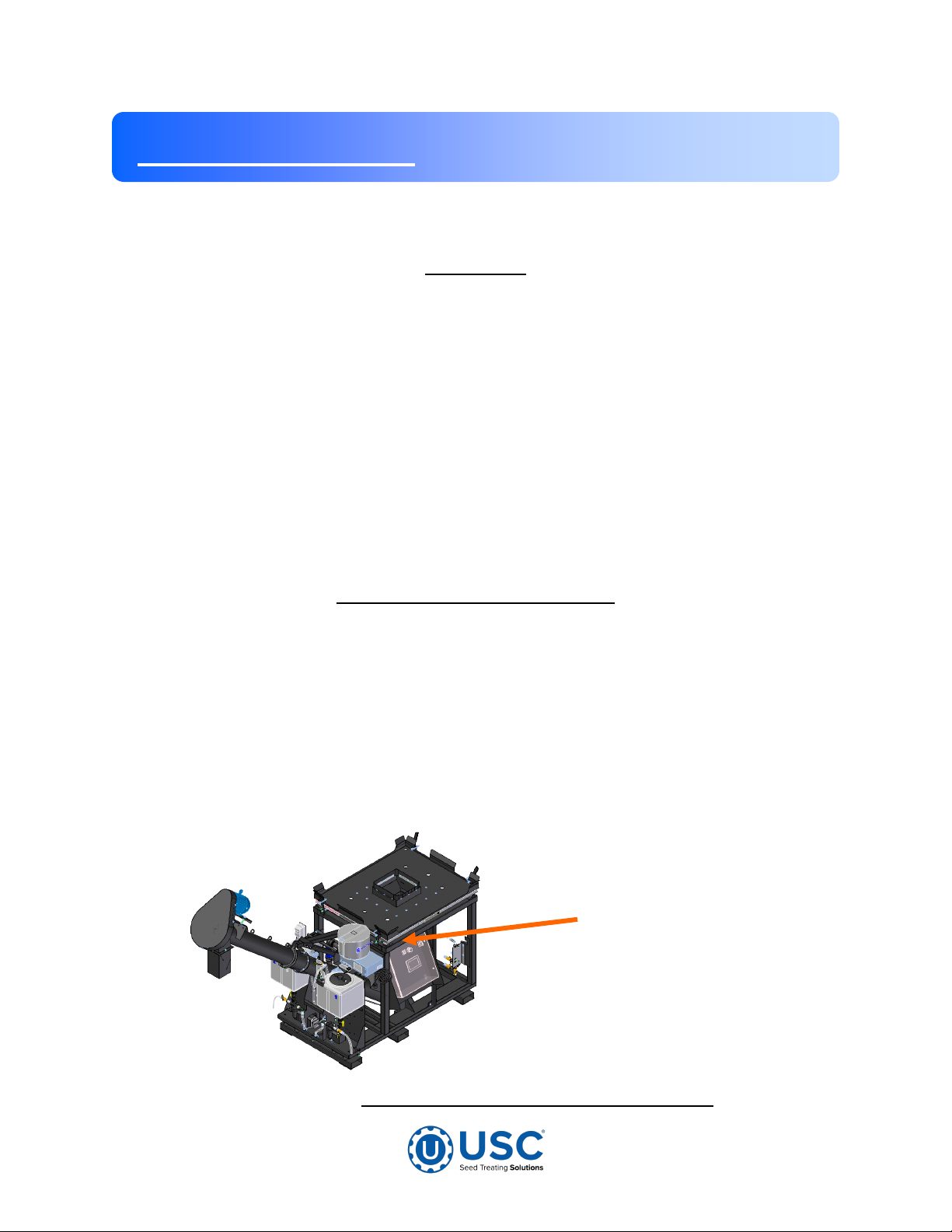
USC AT500H DUAL PUMP STAND User manual

Operators Manual
2320 124th Road, Sabetha, Kansas 66534 www.uscllc.com Phone (785) 431-7900
Document: TD-09-06-1078 Revision: B
AT500H AUTOMATED
TREATER W/LOSS IN
WEIGHT SEED METERING
Software Release: AT500 v2.1
Effective Date: JAN 2023

Page 2
AT500H TREATER
Introduction
Thank you for choosing USC, LLC for your equipment needs. We appreciate your
business and will work diligently to ensure that you are satisfied with your choice.
OVERVIEW
The purpose of this manual is to provide you with the basic information needed to
operate and maintain the AT500H Automated Treater. It does not hold USC, LLC
liable for any accidents or injuries that may occur.
The technical information provided in this document is based on extensive testing
under controlled conditions at the USC research and development facility.
This information is given without guarantee as the conditions of operation and storage
of the equipment are beyond our control. Variables such as temperature, humidity,
viscosity of chemical products and changes in seed size or variety may all effect
the accuracy of application and seed coverage. Periodically check the equipment
calibration while treating and make adjustments as required. This will insure the
optimum seed coverage.
Serial
Number
RECEIVING YOUR EQUIPMENT
As soon as the equipment is received, it should be carefully inspected to make certain
that it has sustained no damage during shipment and that all items listed on the
packing list are accounted for. If there is any damage or shortages, the purchaser
must immediately notify USC, LLC. Ownership passes to purchaser when the unit
leaves the USC, LLC. premises. The purchaser is responsible for unloading and
mounting all components of the equipment.
Document the serial number of the machine for future reference. The serial number
is located on the frame above the treater control panel.
SERIAL NUMBER:__________________________________

Page 3
AT500H TREATER
Section Contents Page #
Section A Safety Instructions................................................................. 4
Safety Labels ......................................................................... 11
Section B Installation ............................................................................ 14
Main Control Panel Connections............................................ 16
Section C Mechanical Operation.......................................................... 18
AT500H Automated Treater Overview ................................... 18
Loss In Weight Slide Gate and Atomizer Overview ................ 19
Peristaltic Pump Head and Motor........................................... 20
Seed Treatment Valves.......................................................... 21
Flow Meters............................................................................ 22
Section D Electrical Operation ............................................................. 23
Main Screen ........................................................................... 24
H-O-A Screen......................................................................... 28
Profile Editing Screens........................................................... 32
Reports Screen ...................................................................... 33
Customers.............................................................................. 34
Ingredients ............................................................................. 35
Seed Profiles.......................................................................... 36
Recipes .................................................................................. 37
Events Screen........................................................................ 38
Section E Calibration & Operation....................................................... 39
Load Cell Calibration.............................................................. 39
Seed Flow Calibration ............................................................ 41
Flow Meter Calibration ........................................................... 43
Treating seed ......................................................................... 45
Section F Troubleshooting................................................................... 48
Proximity Sensor Adjustment Guide....................................... 51
Section G Maintenance ......................................................................... 52
Atomizer ................................................................................. 53
Belt Tensioning and Alignment............................................... 54
Belt Tensioning Specification ................................................. 55
Pumps—Plumbing-Flow Meter............................................... 56
Section H Storage.................................................................................. 58
Section I Limited Warranty.................................................................. 61
Table of Contents

Page 4
AT500H TREATER
Safety Instructions
Section
A
Every year accidents in the work place maim, kill and injure people. Although it may
be impossible to prevent all accidents, with the right combination of training, operating
practices, safety devices and operator vigilance, the number of accidents can be
significantly reduced. The purpose of this section is to educate equipment users
about hazards, unsafe practices and recommended hazard avoidance techniques.
SAFETY WORDS AND SYMBOLS
It is very important that operators and maintenance personnel understand the words
and symbols that are used to communicate safety information. Safety words, their
meaning and format, have been standardized for U.S. manufacturers and published by
the American National Standards Institute (ANSI). The European Community (E.C.)
has adopted a different format based on the International Standards Organization
(I.S.O.) and applicable machinery directives. Both formats are presented below.
Graphic symbols are not standardized but most manufacturers will use some variation
of the ones seen in this manual.
Indicates an imminently hazardous situation which, if not
avoided, will result in death or serious injury.
Indicates a potentially hazardous situation which, if not avoided,
could result in death or serious injury.
Indicates a potentially hazardous situation which, if not avoided,
may result in minor or moderate injury and/or property damage.
Provides additional information that the operator needs to be
aware of to avoid a potentially hazardous situation.
SAFETY
INSTRUCTIONS

Page 5
AT500H TREATER
Mandatory Lockout Power Symbol. Disconnect, lockout and
tagout electrical and other energy sources before inspecting,
cleaning or performing maintenance on this panel.
International Safety Alert Symbol. The exclamation point (!)
surrounded by a yellow triangle indicates that an injury hazard
exists. However, it does not indicate the seriousness of
potential injury. The exclamation point (!) is also used with the
DANGER, WARNING and CAUTION symbols so the potential
injury is indicated.
Electrocution Hazard Symbol. This symbol indicates that an
electrocution hazard exists. Serious injury or death could result
from contacting high voltage.
International Electrocution Hazard. This symbol indicates
that an electrocution hazard exists. Serious injury or death
could result from contacting high voltage.
Mandatory Read Manual Action Symbol. (I.S.O. format) This
symbol instructs personnel to read the Operators Manual before
servicing or operating the equipment.
Mandatory Read Manual Action Symbol. This symbol
instructs personnel to read the Operators Manual before
servicing or operating the equipment.
Notice is used to notify people of important installation,
operation or maintenance information which is not hazard
related.
NOTICE

Page 6
AT500H TREATER
LOCKOUT / TAGOUT PROCEDURES
Lockout/Tagout is the placement of a lock/tag on an energy isolating device in
accordance with an established procedure. When taking equipment out of service to
perform maintenance or repair work, always follow the lockout/tagout procedures as
outlined in OSHA Standard 1910.147. This standard “requires employers to establish
a program and utilize procedures for affixing appropriate lockout devices or tagout de-
vices to energy isolating devices and to otherwise disable machines or equipment to
prevent unexpected energizing, start-up, or release of stored energy in order to pre-
vent injury to employees.”
HAZARD REVIEW
Electrocution Hazard
Electrocution accidents are most likely to occur during
maintenance of the electrical system or when working on or near
exposed high voltage wiring. This hazard does not exist when the
electrical power has been disconnected, properly locked, and
tagged out.
Automatic Start Hazard
This equipment may be controlled by an automated system and
may start without warning. Failure to properly disconnect, lockout,
and tagout all energy sources of remotely controlled equipment
creates a very hazardous situation and could cause injury or
even death. PLEASE STAY CLEAR AND BE ALERT.

Page 7
AT500H TREATER
DANGER! RISK OF ELECTRIC SHOCK AND ARC FLASH
Avoid any alteration to the equipment. Alterations may produce dangerous
situations, where serious injury or death may occur. This equipment shall be installed
in accordance with local installation codes and applicable regulations which should be
carefully followed in all cases. Authorities having jurisdiction should be consulted
before installations are made. Owners/operators are responsible for knowing what
requirements, hazards, and precautions exist with this equipment. Owners/operators
are responsible for informing all personnel associated with the equipment and all who
are in the general area of the equipment, the requirements, hazards, and precautions
that exist with this equipment. Electrical equipment should be installed, operated,
serviced, and maintained only by qualified personnel. A qualified person is one who
has skills and knowledge related to the construction and operation of electrical
equipment and its installation and has received safety training to recognize and avoid
the hazards involved. Only appropriately trained persons who are familiar with and
understand the contents of this manual and all other pertinent product documentation
are authorized to work on and/or with this product. Owners/operators must ensure
that all authorized persons have sufficient technical training, knowledge, and
experience and be able to foresee and detect potential hazards that may be caused by
using the product, by changing the settings and by the mechanical, electrical, and
electronic equipment of the entire system in which the product is used. All persons
working on and with the product must be fully familiar with all applicable standards,
directives, and accident prevention regulations when performing such work. Servicing
and maintaining the equipment should only occur if the equipment is deenergized and
properly locked out and tagged out. If it is unfeasible to service or maintain the
equipment while deenergized, the following standards shall be referenced to ensure
safe practices are being followed and proper PPE is being used: 29 CFR § 1910.333
and 29 CFR § 1910.137. No responsibility is assumed by USC, LLC for any
consequences arising out of the use of this material.

Page 8
AT500H TREATER
YOU are responsible for the SAFE operation and maintenance of your USC, LLC
equipment . YOU must ensure that you and anyone else who is going to operate,
maintain or work around the equipment be familiar with the operating and maintenance
procedures and related SAFETY information contained in this manual. This manual will
take you step-by-step through your working day and alert you to good safety practices
that should be adhered to while operating the equipment
Remember, YOU are the key to safety. Good safety practices not only protect you,
but also the people around you. Make these practices a working part of your safety
program. Be certain that EVERYONE operating this equipment is familiar with the
recommended operating and maintenance procedures and follows all the safety
precautions. Most accidents can be prevented. Do not risk injury or death by ignoring
good safety practices.
• Equipment owners must give operating instructions to operators or employees
before allowing them to operate the machine, and at least annually thereafter
per OSHA (Occupational Safety and Health Administration) regulation 1928.57.
• The most important safety device on this equipment is a SAFE operator. It is the
operator’s responsibility to read and understand ALL Safety and Operating
instructions in the manual and to follow them. All accidents can be avoided.
• A person who has not read and understood all operating and safety instructions is
not qualified to operate the machine. An untrained operator exposes himself and
bystanders to possible serious injury or death.
• Do not modify the equipment in any way. Unauthorized modification may impair the
function and/or safety and could affect the life of the equipment.
• Think SAFETY! Work SAFELY!
GENERAL SAFETY
1. Read and understand the operator’s manual and all safety labels before operating,
maintaining, adjusting or unplugging the equipment .
2. Only trained persons shall operate the equipment . An untrained
operator is not qualified to operate the machine.
3. Have a first-aid kit available for use should the need arise,
and know how to use it.

Page 9
AT500H TREATER
4. Provide a fire extinguisher for use in case of an accident. Store in
a highly visible place.
5. Do not allow children, spectators or bystanders within hazard area
of machine.
6. Wear appropriate protective gear. This includes but is not limited
to:
• A hard hat
• Protective shoes with slip resistant soles
• Protective goggles
• Heavy gloves
• Hearing protection
• Respirator or filter mask
7. Place all controls in neutral or off, stop motor, and wait for all
moving parts to stop. Then disable power source before servicing,
adjusting, repairing, or unplugging.
8. Review safety related items annually with all personnel who will be
operating or maintaining the equipment.
OPERATING SAFETY:
1. Read and understand the operator’s manual and all safety labels before using.
2. Disconnect and disable electrical supply completely and wait for all moving parts to
stop before servicing, adjusting, repairing or unplugging.
3. Clear the area of bystanders, especially children, before starting.
4. Be familiar with the machine hazard area. If anyone enters hazard area, shut down
machine immediately. Clear the area before restarting.
5. Keep hands, feet, hair and clothing away from all moving and/or rotating parts.
6. Stay away from overhead obstructions and power lines during operation and
transporting. Electrocution can occur without direct contact.
7. Do not operate machine when any guards are removed.
8. Inspect welds and repair if needed.

Page 10
AT500H TREATER
PLACEMENT SAFETY
1. Move only with the appropriate equipment
2. Stay away from overhead power lines when moving equipment. Electrocution can
occur without direct contact.
3. Be familiar with machine hazard area. If anyone enters hazard areas, shut down
machine immediately. Clear the area before restarting.
4. Operate the equipment on level ground free of debris. Anchor the equipment to
prevent tipping or upending.
Before placement of the equipment , be sure that ground is
reasonably level. The equipment may topple or work improperly
if the ground is too uneven, damaging the equipment and/or
causing personal injury.
MAINTENANCE SAFETY
1. Review the operator’s manual and all safety items before
working with, maintaining or operating the equipment .
2. Place all controls in neutral or off, stop motors, disable power
source, and wait for all moving parts to stop before servicing,
adjusting, repairing or unplugging.
3. Follow good shop practices:
Keep service area clean and dry.
Be sure electrical outlets and tools are properly grounded.
Use adequate light for the job at hand.
4. Keep hands, feet, hair and clothing away from all moving and/or rotating parts.
5. Clear the area of bystanders, especially children, when carrying out any
maintenance and repairs or making any adjustments.
6. Before resuming work, install and secure all guards when maintenance work is
completed.
7. Keep safety labels clean. Replace any sign that is damaged or not clearly visible.

Page 11
AT500H TREATER
SAFETY LABELS
1. Keep safety labels clean and legible at all times.
2. Replace safety labels that are missing or have become illegible.
3. Replaced parts that displayed a safety label should also display the current label.
4. Replacement safety labels are available. Contact your authorized dealer
How to Install Safety Labels:
• Be sure that the installation area is clean and dry.
• Be sure temperature is above 50oF (10oC).
• Decide on the exact position before you remove the backing paper.
• Remove the smallest portion of the split backing paper.
• Align the sign over the specified area and carefully press the small portion with
the exposed sticky backing in place.
• Slowly peel back the remaining paper and carefully smooth the remaining
portion of the sign in place.
• Small air pockets can be pierced with a pin and smoothed out using the piece
of sign backing paper.
Located on the USC equipment you will find safety labels.
Always be sure to read and follow all directions on the labels.
Guards provided with USC equipment are to remain in place
during operation.

Page 12
AT500H TREATER
Think SAFETY! Work SAFELY!
REMEMBER—If safety labels have been damaged, removed, become illegible, or
parts replaced without safety labels, new labels must be applied. New safety labels are
available from your authorized dealer.
Part # 09-02-0003
Part # 09-02-0002
Part # 09-02-0010

Page 13
AT500H TREATER
Part # 09-02-0001
Part # 09-02-0010 Part # 09-02-0012

Page 14
AT500H TREATER
Installation Section
B
SET-UP
The following steps outline the initial set-up of your USC AT500H Treater :
1. Clear the area of bystanders, especially small children, before moving.
2. Be sure there is enough clearance from overhead obstructions and power lines
or other equipment to move the machine into its working position.
3. Using a forklift, place the AT500H Treater in the desired position on a level surface.
USC highly recommends that the AT500H Treater be set up inside
a building or any covered structure to protect the machine from
weathering.
4. Inspect AT500 Treater thoroughly for screws, bolts, fittings, etc. which may have
come loose during shipping.
5. Check and tighten hose connections.
HIGH VOLTAGE ~ Always disconnect the power source
before working on or near the control panel or lead wires.
HIGH VOLTAGE ~ Use insulated tools when making
adjustments while the controls are under power.
Permanent installation may require additional electrical cords,
chemical tubing, and air lines, since each installation is unique.
NOTICE
NOTICE

Page 15
AT500H TREATER
6. Have a certified electrician provide power to the
seed treating system. Provide convenient shut-
down switches, comply with local electrical codes
and ensure that the system is properly grounded
and bonded. All USC control panels must be
connected adhering to the same electrical re-
quirements as specified in the main control panel
on the power requirement tag (right), or the elec-
trical schematic shipped with the piece of equip-
ment.
Incoming power connected to
these terminals Located in the top
right hand corner in the Treater
Control Panel
Sample Label

Page 16
AT500H TREATER
1. To use the U-Connect Mini remote support capabilities; connect an internet
connected ethernet cable to the Customer Supplied Internet port.
2. There are three MODBUS TCP Ethernet connectors on the Control Panel. These
are used to connect to pump # 3&4, wireless access point for tablet control, printer,
and other peripheral devices to connect to the AT500.
3. Use the USB port to plug in a compact flash device. This will be used to export re-
ports from the system, and other import/export features
4. Connect the cable from any additional individually controlled pump stands to either
of the two wire connectors PJ2111 Aux Device or PJ2112 Aux Device.
5. Connect the cable from Flowmeter Pump #1 to the Pump #1 Flowmeters connector.
The number one pump is the one closest to the control panel. This is factory
connected.
6. Connect the cable from the Pump #1 Motor to the Motor Pump #1 connector. The
number one pump is the one closest to the control panel. This is factory connected.
7. Connect the cable from Flowmeter Pump #2 to the Pump #2 Flowmeter connector.
The number two pump is the one farthest from the control panel. This is factory
connected.
MAIN CONTROL PANEL CONNECTIONS
1
11
10 12
5 6 7 8 139 14
42
MAIN CONTROL PANEL CONNECTIONS
1
11
3
10 12
5 6 7 8 139 14
42

Page 17
AT500H TREATER
8. Connect the cable from the Pump #2 Motor to the Motor Pump #2 connector. The
number two pump is the one farthest from the control panel. This is factory
connected.
9. Auger motor power cord. This is factory connected.
10.Connect the Atomizer Motor cable from treater panel to the atomizer motor. This is
factory connected.
11.Connect the cable from the load cell junction box to the Load Cell Summing Box
connector. This is factory connected.
12.Connect the 8 pin communication cable from the dyadic actuator to the Actuator
Comm connector. This is factory connected.
13.Connect the 4 pin power cable from the dyadic actuator to the Dyadic Power
connector. This is factory connected.
14.Connect the cable from proximity sensor mounted above the Loss In Weight
actuator gate to the Seed Present connector. This is factory connected.
MAIN CONTROL PANEL CONNECTIONS

Page 18
AT500H TREATER
Mechanical Operation Section
C
AT500H AUTOMATED TREATER OVERVIEW
Auger Drive Belt
Assembly
Pro Box
Platform
Atomizer Motor
Plumbing
To Atomizer
Atomizer
Chamber
Auger Motor
Automated
Control
Panel
Treatment Valves
Treatment Tank
Pump Motor
Dry
Additive
Feeder

Page 19
AT500H TREATER
LOSS IN WEIGHT SLIDE GATE AND ATOMIZER CHAMBER
The atomizer chamber consists of a patented design which disperses treatment evenly
to each seed. A motor drives the atomizer head at approximately 1725 RPM’s.
As treatment is being pumped into the atomizer chamber, it drops into the atomizer
head. The centrifugal force of the spinning head forces the treatment to be sprayed
out through a screen covering in all 360 degrees. Meanwhile, seed flows down out of
the box, through the seed gate and down on top of the distribution cone which dispers-
es the seed down around the atomizer head. The atomizer can be easily accessed for
cleaning and maintenance by pulling down on the quick release handle and sliding the
atomizer away from the treater body (see page 53).
Proximity
Switch
Atomizing
Chamber
Adjustable
Slide Gate
Actuator
Quick Release
Atomizer Chamber
Handle
Liquid
Treatment
Port
Atomizer
Motor
Inoculant
Port
Slide Gate

Page 20
AT500H TREATER
The pump stand utilizes a variable speed pump motor and special norprene pump
tubing for liquid metering. Each pump comes equipped with 1 peristaltic pump head.
Liquid will only come into contact with the inside diameter of the pump tubing and not
the pump. This allows for easy cleanup and less maintenance of the pump.
To open the pump head, rotate the lever to the left. Place the pump tubing inside the
pump head so it fits inside the notches and above the rollers (bottom, left). Rotate the
lever back to the right and close the pump head, clamping the hose inside the head
(bottom, right). Wear or fatiguing of the tubing within the pump head due to compres-
sion is normal. When tubing becomes worn or chemical rates begin to slow down,
open the pump head and move the tubing to a different position. If the entire piece of
tubing becomes worn, simply replace with a new section. When not using the pump
stand for several days or when storing, open the pump head and remove the tubing to
prevent any extra compression.
Pump Head Open Pump Head Closed
PERISTALTIC PUMP HEAD AND MOTOR
Other manuals for AT500H DUAL PUMP STAND
4
Table of contents
Other USC Farm Equipment manuals
Popular Farm Equipment manuals by other brands

Kongskilde
Kongskilde Z 665 HYDRO Operator's manual

Agria
Agria 8100 215 Translation of the original operating instructions

360 Yield
360 Yield 360 Y-DROP HAGIE STS 80 instruction manual

SIP
SIP FAVORIT 180 Instruction for work

Jula
Jula 729-028 operating instructions

Ag Leader Technology
Ag Leader Technology CaseIH 2055 manual

AGRI-COVER
AGRI-COVER ROCKSTAR installation instructions

Kellfri
Kellfri 27-DC manual

Claydon
Claydon HYBRID M3F Operator's manual

Zipper Mowers
Zipper Mowers ZI-MD500HS user manual

Pottinger
Pottinger MERGENTO VT 9220 Original operating instructions

Ag Leader Technology
Ag Leader Technology DirectCommand installation instructions