Ushio MIDORI UDC3 User manual

OPERATING MANUAL
UDC3 PORTABLE
LED LIGHT SOURCE

This page is intentionally left blank.

Operating Manual
www.ushio.com 3
1. Introduction.......................................................................................... 3
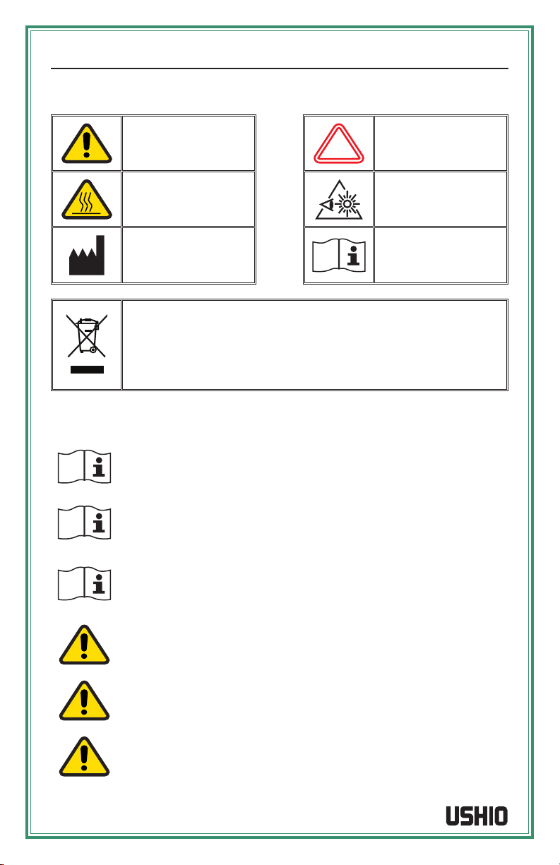
System Symbol Descriptions ............................................................ 3
Warning and Precautions.................................................................. 3
2. UDC3 Specifications and Accessories................................................... 5
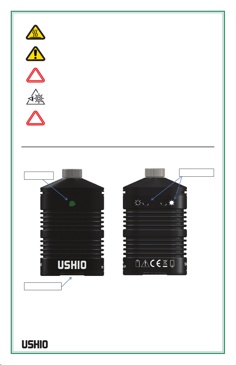
Body Diagram and Descriptions....................................................... 5
Specifications.................................................................................... 6
Accessories....................................................................................... 6
3. UDC3 Operation, Batteries and Charger................................................ 7
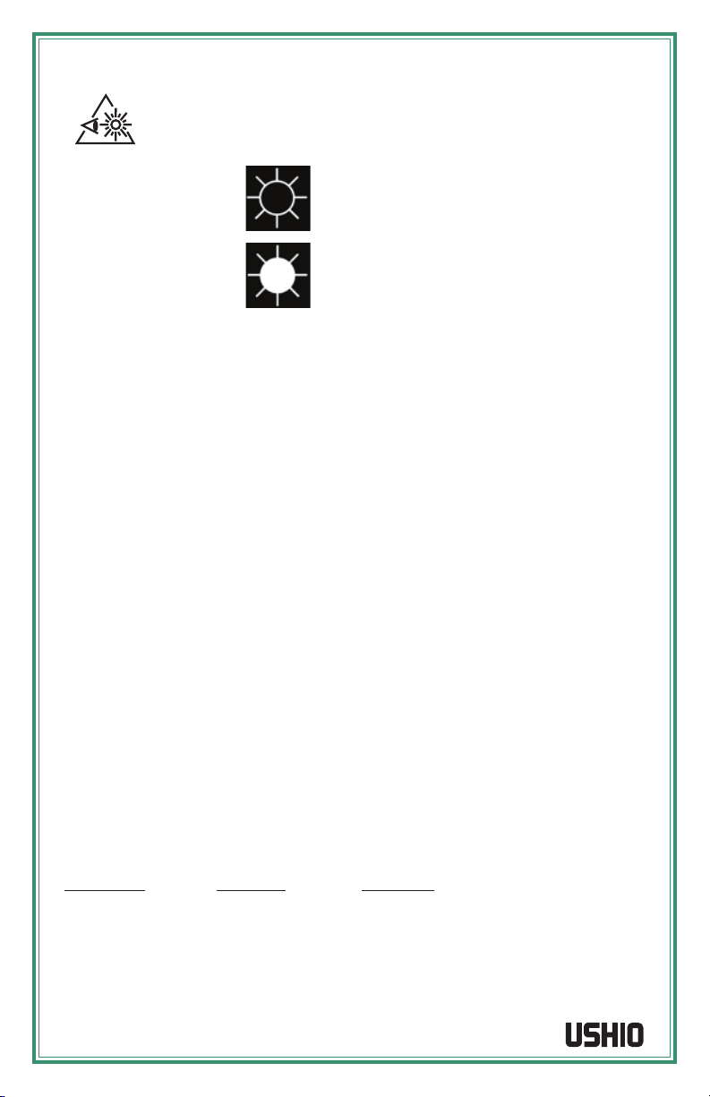
Operation .......................................................................................... 7
Batteries and Charger....................................................................... 8
4. Care and Maintenance ........................................................................ 12
Cleaning .......................................................................................... 12
Drying ............................................................................................. 12
5. Troubleshooting.................................................................................. 13
6. Limited Warranty ................................................................................ 14
7. Regulatory .......................................................................................... 14
8. Agency Approvals............................................................................... 14
Table of Contents
Thank you for purchasing the Midori™ UDC3 LED Light Source which utilizes solid-state
illumination technology. The UDC3 fiber-optic illuminator is intended for industrial
applications that require a handheld light source which features high output, efficient,
compact, and lightweight illumination. The UDC3 utilize eco-friendly LED lighting technology,
exhibits instant-on and electronic intensity dimming capability with long operating
lifetime. The UDC3 is equipped with a rotary collar receptacle to accommodate
common threaded light posts or thumb screw on portable visual scopes.
Preface

Midori™ UDC3 www.ushio.com
4
1. Introduction
Caution
Caution: Hot Surface
Manufacturer
Hazard Warning
Bright Light
Important Information
Do not dispose of this product as unsorted municipal waste. Prepare this
product for reuse or separate collection as specified by Directive 2002/96/
EC of the European Parliament and the Council of the European Union
on Waste Electronic and Electrical Equipment (WEEE). If this product is
contaminated, this directive does not apply.
Warnings and Precautions
Please be sure to handle UDC3 with care at all times. The electrical and optical
components may be damaged by physical trauma, extreme temperatures, or
fluid invasion.
This manual describes the proper procedures for using the UDC3. This also
contains pertinent information on the proper care and handling during use
and storage.
Please read this entire manual carefully before using the UDC3. If you have any
questions concerning the material contained in this manual or the operation or
safety of the equipment, please contact our Customer Service Department at
Check all items upon receipt to assure damage has not occurred during
shipment. Verify compatibility of all components and accessories used with
the UDC3.
Since the UDC3 uses proprietary components, there are no user serviceable
or replaceable parts inside the unit.
Avoid storing or using the UDC3 in areas of heavy traffic where it may sustain
physical damage.
System Symbol Descriptions

Operating Manual
www.ushio.com 5
Unit MAY GET HOT. Provide adequate ventilation to prevent overheating.
DO NOT IMMERSE or store liquids above or on the UDC3.
Any changes or modifications made to this UDC3 that are not expressly
approved by manufacturer will void the warranty.
The high intensity light at the front of the UDC3 and at the tip of borescope
will create bright light. To minimize risk of injury, avoid direct viewing or
contact.
This equipment is not suitable for use in the presence of flammable mixture.
2. UDC3 Description, Specications & Accessories
Fitting Style: The adapter nut allows the UDC3 to attach to the user’s borescope. Rotate
the nut clockwise to attach the UDC3 to a borescope and counterclockwise to remove.
The standard configuration of the Ushio UDC3 is with an adapter nut that threads onto the
standard universal light guide post’s Storz/ACMI adapter thread or by thumb screw for
Olympus style ferrule.
Figure 1: UDC3 Body Diagram; Fitting Style
UDC3 Body Diagram and Descriptions
Power Button
Battery Hatch Door
Intensity Buttons

Midori™ UDC3 www.ushio.com
6
Power Button: The GREEN power button controls the ON/OFF of the UDC3.
WARNING!
Upon power up, the UDC3 drives the LED to high output intensity.
AVOID looking directly at the LED during initial turn ON or anytime while
unit is ON.
Light Intensity Buttons:
Momentary pressing button or holding down the
button next to this symbol decreases the intensity
of the light.
Momentary pressing button or holding down the
button next to this symbol increases the intensity
of the light.
Battery Hatch Door: The battery cover seals the battery and electronics within the body of
the UDC3.
Specications
Dimensions
Length:
Width:
Height:
Weight:
24mm (0.95”)
46mm (1.8”)
81mm (3.2”)
126.8g (4.5 oz)
Illumination System
Type & Power Rating:
Color Temperature:
LED (die) Life Expectancy:
Nominal Cix & Ciy:
Light Emitting Diode (LED); 3 Watts
5700K (Nominal)
35,000 hours*
0.33, 0.34
Power System
Power Source:
Battery Type:
Battery Life at Full LED Power:
Battery Charge Time:
Battery Recharge Cycles:
Battery Powered (2 x RCR123A)
(2) Lithium Ion RCR123A 3.0V, 580mAh - PCM
60 minutes
4 hours
> 300 charge cycles
Environment
Operating Ambient Temperature Range:
Storage Temperature Range:
Humidity:
Mode of Operation:
10ºC to 40ºC (50°F to 104°F)
-15ºC to 55ºC (-5°F to 131°F)
0 – 95% RH
Continuous
Accessories
Part Number Product ID Description
1003987
1004146
5002489
5002490
5002491
UDC3-03
UDC3-07
UPS-01
UPS-02
UPC-02
UAI ACMI Black Midori 3W Direct Connect
UAI Olympus Black 3W Direct Connect
AC/DC Adapter with plug kit (Optional)
Li-Ion RCR123A Rechargeable Battery
2-bay Smart Charger for RCR123A
* Based on LED manufacture recommended operating parameters.

Operating Manual
www.ushio.com 7
3. UDC3 Operation, Batteries and Charger
UDC3 Operation
The UDC3’s internal LED operates on 2 rechargeable Lithium-Ion batteries. When new or
fully charged batteries are installed, the battery capacity is ~60 minutes at full intensity and
~90 minutes at 75% intensity of continuous operation.
Battery Installation
1. At the bottom of the UDC3’s battery hatch door, rotate the locking knob counterclockwise
until the line on the knob is pointing 90° from the indentation mark on the hatch.
Remove the hatch. Refer to figure 2.
2. Insert the batteries into the unit using the battery symbol orientation as a guide.
The negative terminal of each battery should be in contact with the spring on each
circuit board, refer to figure 3. Attach the hatch door then rotate the locking knob
clockwise until the line on the knob is pointing toward the indentation mark.
Note: For added safety, the battery hatch door may only be inserted into the UDC3
body in one direction. If the door does not easily slide into the case, rotate the hatch
door 180°. This ensures the battery polarity cannot be reversed.
To remove batteries, rotate the battery hatch door knob counterclockwise a quarter turn until
it stops, remove the door and allow the batteries to slide out.
Figure 2: Bottom View Figure 3: UDC3 Battery Installation
Installing UDC3 to User’s Borescope
Figure 4: Standard Universal Light Guide Post
1. Hold the UDC3 so that the main body fits comfortably in one hand, allowing easy
manipulation of the adapter nut with the thumb and forefinger.
2. Tighten the adapter nut onto the light guide post by turning rotary collar or thumb
screw clockwise. Do not turn the UDC3 body.
Thumb Screw
ACMI Snap-Ring Groove
Wolf Adapter Thread
Storz Adapter Thread

Midori™ UDC3 www.ushio.com
8
Using the UDC3
1. Turn the UDC3 ON by pressing the GREEN Power ON/OFF button, refer to figure 5.
WARNING!
Upon power up, the UDC3 drives the LED to high output intensity. AVOID
looking directly at the LED during initial turn ON or anytime while unit
is ON.
Momentary pressing button or holding down the button next to this symbol
decreases the intensity of the light.
Momentary pressing button or holding down the button next to this symbol
increases the intensity of the light.
2. Adjust light intensity as needed, refer to figure 6.
3. After use, turn the UDC3 OFF by pressing the GREEN power button.
4. Remove the UDC3 from the borescope by rotating the adapter nut counterclockwise.
5. Remove batteries when UDC3 is not in use for extended periods of time.
Figure 5: GREEN Power Button Figure 6: Intensity Control Switches
Batteries and Charger
Figure 7: Batteries, Charger, Power Supply and Plugs

Operating Manual
www.ushio.com 9
Battery
Standard Part:
Type:
Output Voltage:
Capacity:
Manufacturer/Part Number:
Battery Recharge Cycles:
Battery Charge Time:
RCR123A (Circuit Protected)
Lithium-Ion (Li-Ion), rechargeable
3.0V
580mAh - PCM
Tenergy item #30264
500 charge cycles
4 hour
Figure 8: RCR123A Li-Ion Rechargeable Battery
WARNING!
USE ONLY APPROVED BATTERIES.
Use only pairs of fully charged batteries. Do not mix newly charged and
depleted batteries.
Never mix rechargeable battery with non-rechargeable batteries.
Do not incinerate, disassemble, overcharge or short circuit the battery.
Do not expose the battery to high temperatures above 122ºF/50ºC.
CAUTION!
The batteries should be removed from the UDC3 if it will not be used for
extended time.
Charging the Batteries
1. Plug the AC adapter into a wall outlet.
2. Connect the AC power adapter to the DC IN jack located at the top of the charger.
Make sure no battery is installed. The LED indicator will turn green when the charger
is ready.
3. Slide the battery into the charger, making sure the negative side of the battery is
inserted into the charger first against the spring contact. The LED indicator will turn
RED when the battery is charging.
4. LED indicator solid red light indicates batteries are charging and not ready for use.
5. LED indicator solid green light indicates installed batteries are fully charged and
ready for use.
6. When battery has been fully charged, pull the battery out of the charger and unplug
the AC adapter from the charger.

Midori™ UDC3 www.ushio.com
10
Charger
Electrical Characteristics
Input/output Characteristics of External Adapter
Input Voltage:
DC output no-loading voltage:
Output Current:
AC 100V~240V 50Hz/60Hz
12.0V ±5%
0.5A
Input/output Characteristics of External Car plug
Input Voltage: DC 12.0V
Output Characteristics of Charger
No-loading voltage:
Rated Input Current
(Normal Charging Condition):
Output Noise :
Input Voltage Range:
4.50V ±0.05V × 2CH
250 ±50mA × 2CH @CV = 3.7V
≤ 150mV @CC = 200mA
2.50V-4.55V × 2CH
LED-alter Current: When the battery is fully charged, LED turns red to green,
and the current at that time called LED-alter Current
= 70 ±30mA × 2CH.
Charging Mode: Constant current and constant voltage charging
Short circuit current: When a short circuit is detected, the charger will go into
short circuit protection mode and the Red LED indicator
light turns OFF. The short circuit current ﹤ 600mA/CH.
Reverse Irrigation Current: ≤ 1mA
In normal charging process, when the input power cuts
off suddenly, the current which is released by discharge
is called reverse irrigation current.

Operating Manual
www.ushio.com 11
Charger Features
• Manufacturer supplied charger is a 2-bay Li-Ion battery smart charger with MCU
control which features:
– Independent charging channels;
– Constant current and constant voltage charging;
– Ensures the quality and safety of charging process.
• Worldwide AC input voltage 100-240V, 50Hz/60Hz. The kit includes AC adapter
with interchangeable power plugs that may be used for US, EU, UK and AU.
• Two-color LEDs indicate charging status.
• Each LED indicates the corresponding channel.
CAUTION!
• DO NOT use charger to charge other type of batteries.
• DO NOT operate the charger when the temperature is higher than 40°C.
We recommend operating when the temperature is lower than 35°C.
Batteries may get warm during charging.
• USE ONLY Tenergy Battery #30264.
• DO NOT use charger and batteries in any acidic, alkaline or corrosive
environment.
• DO NOT expose charger to rain, snow, water, gas, oil, etc.
• DO NOT short circuit charging terminals.
WARNING!
• Do not expose charger to fire, water or moisture.
• To avoid electrical shock, do not disassemble the charger.
• No user-serviceable parts inside the charger.
• Follow local regulations for disposal of electrical components or batteries.
Charger LED Indication
No Battery:
Charging:
Fully Charged:
Short Circuit/Reverse Polarity:
Solid Green
Solid Red
Solid Green
No LED Indication
Figure 9: Tenergy Li-Ion 2-bay Battery Smart Charger

Midori™ UDC3 www.ushio.com
12
4. Care and Maintenance
UDC3 Cleaning
The UDC3 is rated for water resistance. The UDC3 is rated for slight water contact and mild
detergent cleaning solutions only. However, it should NOT BE IMMERSED in water or cleaning
solutions for any prolonged periods of time. After cleaning, remove UDC3 from cleaning
solution, dry and store the device in a clean and dry environment.
WARNING!
Failure to comply with the following may result in damage to the UDC3 and
will void the product warranty.
Use caution when cleaning the UDC3; some methods may be harmful and could result in
extensive damage. Manual cleaning is the recommended method. Certain cleaning agents
may damage the device’s materials. Only use water with a mild detergent such as a nonabrasive
hand or dishwashing soap. Do not immerse the UDC3 in an ultrasonic cleaner.
CAUTION!
Ensure that the battery hatch door is fully tightened on the O-ring seal to
prevent liquid intrusion into the battery compartment.
Never use any organic solvents to clean the UDC3, other than isopropyl
alcohol.
Drying the UDC3
If the UDC3 comes in contact with liquid, rinse with isopropyl alcohol and then dry with
compressed air, commercial compressed gas canisters or dry damp cloth.
Note: Air dry is highly recommended to reduce contamination of the optical
components and reduce the possibility of oxidation of the materials used in the
construction of the UDC3.
CAUTION!
Do not allow the UDC3 to remain in liquid cleaning solution for prolonged
period of time.
In addition, thoroughly dry the battery hatch door seal around the O-ring, with compressed
air or by thoroughly wiping any excess liquid from this area, prior to removing the battery
hatch door. This will prevent any trapped fluid from entering the battery compartment and
exposing the electronics to fluids.
CAUTION!
Ensure there is no trapped liquid between the battery hatch door and body
prior to removing the battery hatch door.

Operating Manual
www.ushio.com 13
5. Troubleshooting
PROBLEM POSSIBLE CAUSE ACTION
Loss of Illumination
Battery charge is low Replace batteries with freshly
charged batteries.
Batteries cannot supply sufficient
current at this power setting.
Replace batteries with freshly
charged batteries.
Verify batteries have been installed
in the correct orientation.
Battery mismatch
Reduce the light intensity and
continue using the current battery.
Recharge the batteries as soon as
possible.
UDC3 Light output
flashing
Battery charge is low Reduce the light intensity and
continue using the current battery.
This is normal behavior indicator
when the battery charge is low.
Remaining run time is about 2
minutes.
Recharge the batteries as soon as
possible.
Light Guide does
not attach properly
to the borescope
The borescope has an adapter
on its light post.
Remove the adapter and try
attaching again.
The borescope and UDC3 do
not have a compatible coupling
system.
Use an adapter sleeve or switch
to UDC3 with a different type of
adapter nut.
Light intensity is
low
Foreign material or film on LED
output taper.
VERY carefully clean the LED
surface from visible contamination
with a cotton swap and isopropyl
alcohol. Do not use acetone or
other solvents.
UDC3 becomes hot
after prolonged use
at full power
UDC3 has been left on for more
than 30 minutes at full power.
Turn the UDC3 to a lower intensity
setting if the examination must
continue past 30 minutes.
Turn the UDC3 OFF for a few
minutes to permit adequate cool
down of the body.

Midori™ UDC3 www.ushio.com
14
6. Limited Warranty
Ushio America, Inc. warrants the Midori™ UDC3 LED Light Source, when new, to be free of
defects in material and workmanship and to perform in accordance with the manufacturer’s
specifications when subject to normal use and service for a period of one (1) year from the
date of purchase from Ushio America or an authorized agent. Ushio America will either repair
or replace any components found to be defective or at variance from the manufacturer’s
specifications within this time at no cost to the customer. It shall be the purchaser’s responsibility
to return the instrument to the authorized distributor, agent, or service representative.
All non-warranty repairs will be warranted to be free from defects in materials and workmanship
for a period of ninety (90) days from the date of the invoice.
This limited warranty does not cover the breakage or failure due to tampering, misuse,
neglect, accidents, improper installation, modification, shipping, or to improper maintenance,
service, fluid invasion and cleaning procedures. This limited warranty is also void if the
instrument is not used in accordance with the manufacturer’s recommendations or if
required service is performed by anyone other than Ushio America or an authorized
agent. The purchase date determines limited warranty requirements. No other express
or implied limited warranty is given. Suitability for use of the device for any procedure
shall be determined by the user. Ushio America, Inc. shall not be liable for incidental or
consequential damages of any kind.
7. Agency Approvals
The UDC3 has been tested to, and found in conformance with, the following standards:
EN50581:2012
2006/95/EC (93/68 EEC) – Low Voltage Directive
IEC 62471:2006 LED Photobiological safety lamp standard, categorized as
Risk Group 2 (Moderate risk).
2011/65/EU – RoHS Directive
WEEE
8. Manufacture Contact Information
Manufactured and Serviced by:
Ushio America, Inc.
5440 Cerritos Ave.
Cypress, CA 90630 USA
Tel: +1.714.236.8600
Fax: +1.714.229.3180
Toll-Free: +1.800.838.7446
www.ushio.com

This page is intentionally left blank.

082016-UDC3
5440 Cerritos Avenue, Cypress, CA. 90630
TEL: 714-236-8600, FAX: 714-229-3180
www.ushio.com
Scan with a smartphone
to view this product online.
MADE IN USA
Other manuals for MIDORI UDC3
1
Table of contents
Other Ushio Lighting Equipment manuals
Popular Lighting Equipment manuals by other brands

Nichia
Nichia 193F Series Assembly

Iluminarc
Iluminarc Ilumipod 18g2 IP Optic RGB Quick reference guide

LITESHEET
LITESHEET BriteCor AC BTS Series installation manual

Milwaukee
Milwaukee M12 PACKOUT AREA LIGHT Operator's manual

Lindby
Lindby 8032270 user manual

Speck pumps
Speck pumps Badu Stream II Installation, operating and service manual

ECOLOCITY
ECOLOCITY Ribbon Star Flex LED Strip Light manual

Triton Blue
Triton Blue SIRIUS 7 LED 8W RGBW user manual

Colorist
Colorist PANEL 36Qa Quick reference guide

MJ LED LIGHTNING
MJ LED LIGHTNING MJ-2610D18-4IN1 user manual

Mio
Mio ELLIOT M1982646 instructions

ETC
ETC Source Four Revolution Scroller Cartridge quick guide