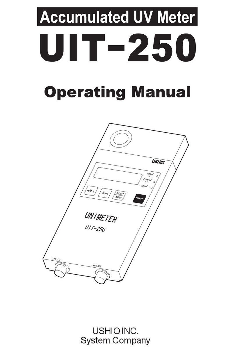
Ushio UIT-201 User manual

USHIO INC.
System Company


i
1000033245-00
Thank you for purchasing the Digital UV Intensity Meter UIT-201.
This manual provides a summary for the Digital UV Intensity Meter UIT-201 as well as
instructions for its use.
Keep this manual in a safe place in order to be able to refer to it at any time.
Precautions for use
These "precautions for use" describe information that needs to be followed in order to use
this product correctly and safely. Read this portion carefully and make sure that you
understand it before moving on.
Sections that display this warning are content where
"Failure to heed could lead to heavy injury or death."
Sections that display this are content where "Failure to
heed could lead to injury or physical damage."
This is noted for items concerning operation and main-
tenance of the equipment that are important to know or
if not in compliance or corrected damage may be caused
to the unit.
Warning
•The UV leaking from the UV curing system can damage you eyes or skin within
a short period of time. When using the UIT-201 near a leaking UV, be sure to wear
protective glasses, and do not expose your skin directly to the UV. The recom-
mended protectors are:
- Protective glasses: RS-24U (SPL3~5) manufactured by Riken Optics.
- Protective mask: UV protector mask manufactured by USHIO INC.
(Drawing No. 2046-1981)
Warning
Caution
Imporant
Read the following warnings prior to use of the
unit.

ii 1000033245-00
Caution
•The photodetector is formed using optical components; therefore pay attention
to the environment (temperature and humidity).
Especially the optical filter which demonstrates prescribed functionality within
the specified temperature and humidity environment. In conditions outside the
specified environment functionality can not be demonstrated and the element
itself deteriorates.
Store in a location where the environment such as the temperature and humidity
can be controlled such as using a desiccator.
•Do not apply any shock to the UIT-201 unit and the photodetector. Otherwise,
the incorporated devices may be broken or fail to operate properly.
•Use alcohol to clean the UIT-201 unit. Do not use any organic solvent such as
thinner or acetone since it damages the unit body.
•Do not use any photodetector other than ones designated by our company.
Important
•The measurement capability of this irradiance meter is up to "1999"; however,
for cases where light is high power, the linearity of the photodetector worsens.
Depending on the photodetector used, the measurement range may be reduced.
Confirm the measurement range of the photodetector using its operating manual.
•For cases where photodetectors that have an irradiance sensitivity other than
12.0~1500 µA/(W/cm2) are read directly, follow the operating manual for the
photodetector to correct the sensitivity.
•A very weak current flows through the UIT-201 unit form the battery even if the
power is off. Remove the battery when not using the unit for a long period of
time.
•If there are particles on the photodetector or if it is dirty it can cause error in the
measurement.
Check to make sure that there are not any particles and that the photodetector is
not dirty. If it is dirty, wipe it with a piece of gauze soaked in alcohol.
Read the following cautions prior to use of the
unit.
Read the following important points prior to
use.

iii
1000033245-00
•When turning on the unit, prevent light from reaching the photodetector.
When the unit is turned on the photodetector is initialized and the irradiance
value is set to 0. Therefore, if the unit is turned on while the photodetector is
exposed to light the irradiance value is still set to 0. All measurement values made
thereafter will contain error (will be offset).
•If the measured irradiance exceeds the full scale irradiance, it is regarded as over-
scale and is indicated in the display monitor.
Increase the measurement range and perform the measurement.
•If is indicated on the display monitor, it is regarded as a battery
voltage error. This indicates that the battery level is low. Replace the battery. Be
sure to check that the power is turned off when replacing the battery.
•If an AC adapter is used while batteries are left in the unit, do not select the power
select switch when the power is on. This may cause an error or failure.
•The sensitivity of this photodetector is calibrated using monochromatic light.
Multiple photodetectors of the same type provide the same indication for mea-
surement of designated monochromatic light - light sources.
When the light source emits a wavelength distribution take into consideration the
spectroscopic sensitivity characteristics of the photodetector shown in chapter
15 of this operating manual. These spectroscopic sensitivity characteristics are
representative values. When measuring a general light source that has a wave-
length distribution, there is variability in the value indicated by multiple photo-
detectors of the same type due to variability in the spectroscopic sensitivity
characteristics of the units.
•Equipment shown in this catalog, any products using the equipment or technolo-
gies relating the equipment fall under the category of security control relating
freight or technologies under the provisions of the Foreign Exchange and Foreign
Trade Control Law. You have to obtain permission from the Government of
Japan before exporting them from Japan.

iv 1000033245-00

1
1000033245-00
4. Instructions for use
Contents
Precautions for use ............................................................... i
Contents ............................................................................... 1
1. Outline .............................................................................. 2
2. Configuration .................................................................... 3
3. Names for each of the Sections ....................................... 4
4. Instructions for use ........................................................... 6
4-1. Preparation prior to measurement ............................................. 6
4-1-1. Insertion and replacement of batteries ........................................................ 6
4-1-2. Using the AC Adapter .................................................................................. 6
4-1-3. Setup and Exchange of the Photodetector ................................................. 7
4-2. Measurement Method ............................................................... 8
4-2-1. Turning unit on ............................................................................................. 8
4-2-2. Turning unit off ............................................................................................. 8
4-2-3. Adjustment of sensitivity .............................................................................. 8
4-2-4. Measurement of irradiance .......................................................................... 9
4-3. Output of Measurement Results .............................................. 10
5. Error Display................................................................... 11
6. Troubleshooting .............................................................. 12
7. Warranty and Repair ...................................................... 13
7-1. Warranty .................................................................................. 13
7-2. Repair ...................................................................................... 13
7-3. Calibration (Main Unit and Photodetector Unit) ........................ 13
8. Specifications ................................................................. 14
9. Disclaimer ...................................................................... 16

21000033245-00
4. Instructions for use
1. Outline
The UIT-201 is a compact Digital UV Intensity meter.
Use in combination with photodetectors (UVD-365PD, UVD-405PD, etc.) enables
measurement of the strength of light at various wavelengths.
This irradiance meter is small and lightweight and as the measurement is indicated
using a digital display using mW/cm2units, measurement can be made easily and
without error at the worksite. In addition, the irradiance surface area of the photode-
tector for this irradiance meter is designed small enabling measurement of high power
light spots.
This irradiance meter uses two types of power sources, either batteries or an optional
AC adapter.
UIT-201 Unit
1. Outline

3
1000033245-00
4. Instructions for use
2. Configuration
Please check components that are provided with the unit.
[Options for sale separately]
[UIT-201]
UIT-201 unit
2 m extension cable
(2441-7711)
AC adapter
(6003-3042)
Photodetector
(UVD-365PD,
UVD-405PD etc.)
Operating manual
Analog signal
output cable (1.5 m)
(2441-7687)
Connector model:
HR10-7P-6P
(Hirose)
Trunk case
AAA alkaline
batteries (3)
2. Configuration
* Contact our sales department for photodetectors other than those noted above.

41000033245-00
4. Instructions for use
3. Names for each of the Sections
(1)
(8)
(10)
(9)
(19)
(18)
(7)
(5)
(6)
(14)
(13)
(15)
(12)
(11)
(16)
(4) (3)(2)
(17)
Analog signal output cable Photodetector
Main unit
3. Names for each of the Sections

5
1000033245-00
4. Instructions for use
(1) UIT-201 Unit
(2) Sensor connector
Used for connecting the photodetector.
(3) Analog signal output terminal
Used to output an analog signal.
(4) Analog zero adjustment volume
Used for adjusting the zero analog output.
(5) Photodetector sensitivity value (CAL value) adjustment volume
Used for selecting the photodetector sensitivity.
(6) Photodetector sensitivity select switch
Used for selecting the photodetector sensitivity.
(7) Display monitor
Used for displaying irradiance value and sensitivity.
(8) H range display light
Blinks when H range is selected while irradiance is being measured.
(9) M range display light
Blinks when M range is selected while irradiance is being measured.
(10) L range display light
Blinks when L range is selected while irradiance is being measured.
* The display lights indicated by (8) ~ (10) all blink while in sensitivity adjustment
mode.
(11) H/M/L switch
Used for selecting the measurement range.
(12) Hold switch
Used for continuously display of irradiance value.
(13) Irradiance/CAL switch
Used for selecting between irradiance measurement mode and sensitivity value ad-
justment mode.
(14) Power switch
Used for turning the power supply on and off.
(15) Power supply select switch
Used for selecting the power supply that drives this unit.
BATT: for measurement when using batteries.
DC IN: for measurement when using an external power supply (AC adapter etc.).
(16) AC adapter connection terminal
Used for connecting the external power supply such as an AC adapter (option).
(17) Battery cover
Three AAA batteries are stored inside.
(18) Analog signal output cable
Used for connecting to the recorder etc.
(19) Photodetector
3. Names for each of the Sections

61000033245-00
4. Instructions for use
4-1. Preparation prior to measurement
This irradiance meter operates on batteries or an AC adapter (option).
Follow the following instructions to perform set up.
4-1-1. Insertion and replacement of batteries
This irradiance meter operates on 3 AAA batteries. This unit is not shipped with bat-
teries. Use the following instructions to put the batteries into the unit.
(1) Remove the battery cover on the rear surface of the unit.
(2) Insert 3 AAA batteries according to the direction indicated on the irradiance
meter body.
(3) Replace the battery cover.
(4) Set the [power supply select switch] to BATT.
4-1-2. Using the AC Adapter
This irradiance meter is able to use an AC adapter as an option.
When using an external power supply for measuring, purchase an AC adapter sepa-
rately for use.
(1) Connect the connection terminal of the AC adapter to the AC adapter connector
on the irradiance meter.
(2) Set the [power supply select switch] to "DC IN".

7
1000033245-00
4. Instructions for use
Important
1. When preparing an AC adapter on your own, use a transformer type
unit that can stably supply 3.15 V/50 mA.
If a switching type AC adapter is used, the unit may be affected by
noise.
2. When the load is small with respect to the capacity, a voltage that is
higher than the rated voltage is output by the AC adapter that is a cause
of erroneous operation, failure, and breakage of this irradiance meter.
Confirm with data for the adapter to make selection for use.
3. For the polarity of the plug, select a device that has positive on the
center.
4. When using an AC adapter while leaving batteries in the unit, turn the
power supply off before selecting the [power supply select switch].
Changing of the [power supply select switch] with the power supply on
is a cause of error and/or failure.
4-1-3. Setup and Exchange of the Photodetector
Through exchanging the photodetector of the UIT-201, various wavelength ranges of
UV light can be measured.
•Setup of the photodetector
(1) Check to make sure that the power supply is off.
(2) Insert the connector of the photodetector into the sensor connector of the irradi-
ance meter.
•Removal of the photodetector
(1) Check to make sure that the power supply is off.
(2) Hold onto the body of the connector for the photodetector and pull it straight
out.

81000033245-00
4. Instructions for use
4-2. Measurement Method
4-2-1. Turning unit on
(1) Prevent light from reaching the receiving surface, and push the switch.
- Next, is indicated on the display monitor.
Important
1. Turn the unit on only after attaching the photodetector.
If the photodetector is attached after turning unit on, an incorrect value
is displayed.
2. Prevent light from reaching the photodetector surface when turning the
unit on.
(2) All of the display lights blink.
(3) Initialization operation is finished in roughly 5 seconds and irradiance can be
measured.
4-2-2. Turning unit off
(1) Push the switch for roughly 1 second.
- Numbers on the display monitor disappear.
- The power is turned off.
4-2-3. Adjustment of sensitivity
After turning the UIT-201 on, it starts up in H range irradiance sensitivity measure-
ment mode.
Prior to measurement, following the procedure below, check to make sure the num-
bers displayed on the unit are close to the numbers for the photodetector sensitivity
given in the inspection sheet.
Important
If the numbers in the display of the unit and those shown for sensitivity
of the photodetector differ significantly or if using a photodetector other
than the one attached when shipped from the factory, adjust sensitivity
such that the photodetector sensitivity is set to that given in the inspec-
tion sheet for the photodetector.
Note, the sensitivity value is set to "1000" when shipped from our com-
pany.

9
1000033245-00
4. Instructions for use
(1) Check the sensitivity of the photodetector being used.
- Sensitivity is noted in the inspection sheet that came with the photodetector.
- If the units noted in the inspection sheet that came with the photodetector is
not µA/(W/cm2) convert it to µA/(W/cm2).
(2) If sensitivity values are different, press the switch.
- This transitions to sensitivity adjustment mode.
- All of the display lights on the display monitor blink.
- The current sensitivity is indicated on the display monitor.
(3) Select the [photodetector sensitivity select switch] on the side of the unit.
Photodetector sensitivity Select switch
12.0~150.0 µA/(W/cm2) L
120~1500 µA/(W/cm2) H
(4) Using a slotted screwdriver turn the [photodetector sensitivity value adjust-
ment volume].
- Adjust the photodetector sensitivity so that the display monitor reading is
±2% or less.
(5) After setting, with unit set up so that light can not get to the photodetector, press
the switch again.
- Perform zero correction for the new sensitivity sensitivity.
- Here, is indicated on the display monitor.
(6) After correction, this returns to the measurement range the unit was in prior to
transition to sensitivity adjustment mode.
4-2-4. Measurement of irradiance
In irradiance measurement mode, measurement can be selected between H range,
M range, and L range, depending on the strength of the light being measured.
H range is used for strong light and L range is used for weak light. Here the display
light that indicates the range selected blinks.
When the display exceeds "1999", is indicated on the display monitor showing that
the range needs to be changed to perform measurement.
(1) When changing the measurement range, push the switch.
- Each time this button is pushed, the measurement range changes from H range
→M range →L range →H range.
- The display light that indicates the range changed to blinks.

10 1000033245-00
4. Instructions for use
(2) If the display reading is difficult to read due to sever changes in the light, press
the switch.
- The irradiance on the display monitor is held.
- The display light that indicates the selected range lights up.
- Pressing the switch again releases the hold.
4-3. Output of Measurement Results
Analog output
Used for recording light fluctuation using a recorder (oscilloscope, pen recorder etc.).
Connect the analog signal output cable that is included to the recorder device that you
are using.
(1) Connect the analog signal output cable that came with the unit to the analog
signal output terminal.
- Connect the orange and white wires of the analog signal output cable respec-
tively to the +, −terminals of the recorder device (oscilloscope, pen recorder
etc.).
- Full scale can be used for 2 V.
- Response speed of the analog output is roughly 50 msec.
Important
1. The output impedance is 1 kΩ. In order to provide a correct measure-
ment it is recommended that the input impedance of the recorder de-
vice be greater than 1 MΩ.
2. If the input impedance of the recorder device is low, the measured
value may be low.
(2) When performing zero adjustment of the output, use a slotted screwdriver and
turn the [analog zero adjustment volume].

11
1000033245-00
4. Instructions for use
5. Error Display
The UIT-201 indicates the following two kinds of errors on the display monitor de-
pending on its condition:
Error
Display Error Contents Error Cause Defective Cause
Abnormal
battery voltage
error.
The battery level
has run low.
Turn off the power, and
replace the battery cells
with new ones.
System down
error.
The CPU may have
failed.
Turn off the power, and
turn it on again.
* When is displayed, the display can be cancelled by pressing the
switch. Here, will not be displayed again until the power is turned off
so be careful for the amount of power remaining in the batteries.
5. Error Display

12 1000033245-00
4. Instructions for use6. Troubleshooting
6. Troubleshooting
If it looks like there may be a failure, check the following items and perform the
measure(s) described.
No. Symptoms Check for Defective Cause
1. Display flickers. Dead batteries,
insufficient voltage
from batteries.
Replace the batteries with
new ones.
2. Even though unit is
exposed to UV rays, the
display remains at 0 and
does not change.
Is the irradiance
meter on?
Select the irradiance me-
ter off and on.
No. Symptoms Check for Defective Cause
1. Though UV light expo-
sure is not performed,
the monitor display does
not return to 0.
Check for an ab-
normality with the
photodetector cord.
Photodetector short cir-
cuit.
2. Even though unit is
exposed to UV rays, the
display remains at 0 and
does not change.
Check for an ab-
normality with the
photodetector cord.
Photodetector cord break
(disconnection).
3. Measurement value
(irradiance value) sud-
denly went down.
Is there an abnor-
mality with the
appearance of the
photodetector?
Deterioration of the
photodetector filter.
4. An abnormal sound
comes from within the
photodetector.
Does the
photodetector make
a sound when
lightly shaken?
Loosening of material
used to fix filter inside the
photodetector.
5. Abnormal sound from
the irradiance meter
body.
Does the irradiance
meter body make a
sound when lightly
shaken?
Loosing of fixing screws
for the circuit board inside
the irradiance meter.
6. Smoke coming from
irradiance meter.
Are the batteries
positioned cor-
rectly?
Insertion of batteries with
positive and negative
terminals backwards.
If the unit has any of the following symptoms it needs to be repaired; therefore, con-
tact our company.

13
1000033245-00
4. Instructions for use
7. Warranty and Repair
7-1. Warranty
This measuring instrument is delivered after USHIO has thoroughly inspected the
instrument and check that its performance satisfies the specifications. If this instru-
ment fails due to its material or poor workmanship, or if it has failed due to an acci-
dent during transportation, please contact USHIO. The warranty term of this instru-
ment shall be one year after its delivery or three months after repair. If this instrument
fails under normal operating conditions within this warranty term, USHIO will repair
or replace the instrument free of charge.
However, this instrument is not covered by warranty I fit is used in a wrong manner (a
manner not described in the operation manual) or in the careless manner, if it is modi-
fied, or if it has failed due to a natural disaster, etc.
7-2. Repair
If this instrument is judged as to have failed, or if you are unclear on any point, please
inform USHIO of the model manufacturing number and symptom in details. How-
ever, please understand that USHIO is not obligated to repair the instrument if it is
modified.
7-3. Calibration (Main Unit and Photodetector Unit)
In order to ensure measurement accuracy, it is recommended that this instrument be
calibrated once every 6 months.
If you have any questions concerning repair or calibration please contact your repre-
sentative salesperson.
7. Warranty and Repair

14 1000033245-00
4. Instructions for use
8. Specifications
UIT-201 Unit Specifications
Display Liquid crystal digital display: 4 digits
Functions Real time irradiance, range switch (3 step select between H, M, and
L), sensitivity (CAL value) adjustment
Photodetection
sensitivity
Maximum
measurement value
Minimum
resolution
When using
UVD-365PD 12.0~150.0 µA/(W/cm2) 1999 mW/cm20.01 mW/cm2
Measurement
Range
When using
UVD-405PD 120~1500 µA/(W/cm2) 199.9 mW/cm20.001 mW/cm2
Analog output
Output voltage
Output impedance
Response speed
1.999V (for full scale output)
Less than 2 kΩ
Roughly 50 msec.
Power
3 AAA batteries or an AC adapter external power supply
(selection based on power select switch)
•When using batteries: can be used for 45 hours continuous when
used normally
•The AC adapter is an option
Dimensions (mm) 80 (W) x 180 (D) x 19 (H)
Weight (g) 150 g (only for main unit and does not include batteries or any
options)
19.5
3
9
33
1
2-M3 depth of 8 mm
installation hole
180
80 19
UIT-201 Unit
Photodetector (UVD-365PD, UVD-405PD)
8. Specifications
Table of contents
Other Ushio Measuring Instrument manuals
Popular Measuring Instrument manuals by other brands

Agilent Technologies
Agilent Technologies Agilent 4396B Performance test manual

Garland
Garland M10G BP Series installation guide

Xantrex
Xantrex LinkLITE installation instructions

Chauvin Arnoux
Chauvin Arnoux AEMC 6527 user manual

PCB Piezotronics
PCB Piezotronics 353B18 Installation and operating manual

Fluke
Fluke 789 Quick reference guide