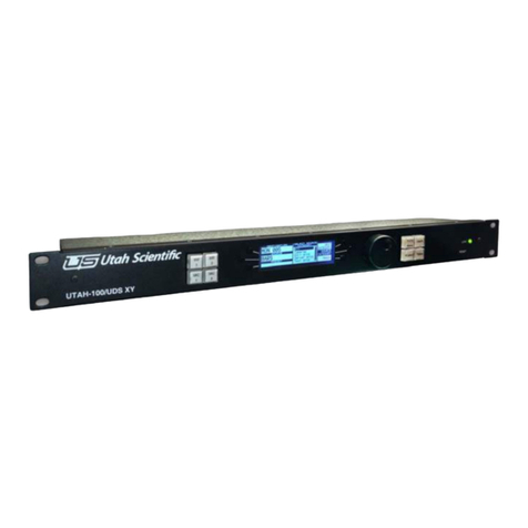
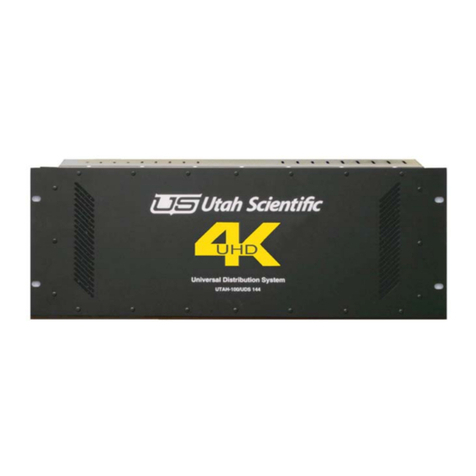
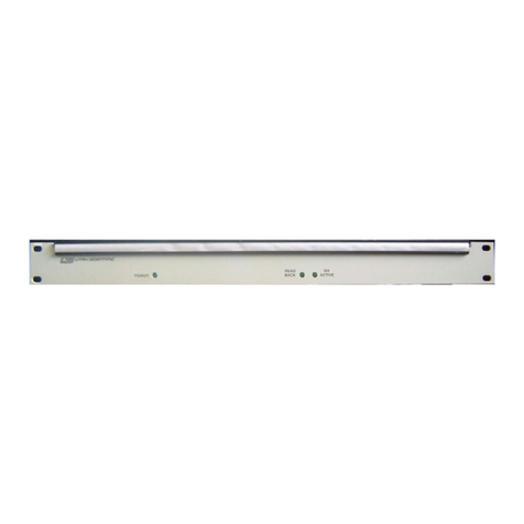
UTAH SCIENTIFIC UTAH-100/UDS XY Manual instruction

UTAH-100/UDS
System Setup and Operation

ii
UTAH 100/UDS Operations Guide
• Document Number: 82102-0032
• Document Version: 1.6.1
• Date: December 18, 2015
• Printed in U.S.A.
Copyrights and Trademarks
© 2015 Utah Scientific, Inc., All rights reserved. Any use or reproduction of this
guide’s contents without the prior written consent of Utah Scientific, Inc. is
strictly prohibited.
•UTAH 100 is a trademarks of Utah Scientific, Inc.
•Windows, Windows 2000 and Windows NT and XP are registered trademarks
of Microsoft Corporation.
•All other product names and any registered or unregistered trademarks men-
tioned in this guide are used for identification purposes only and remain the
exclusive property of their respective owners.
Notice
Information contained in this guide is subject to change without notice or
obligation. While every effort has been made to ensure that the information is
accurate as of the publication date, Utah Scientific, Inc. assumes no liability for
errors or omissions. In addition, Utah Scientific, Inc. assumes no responsibility
for damages resulting from the use of this guide.
FCC Compliance (USA) and Digital Equipment Com-
pliance (Canada)
This equipment has been tested and found to comply with the limits for a Class
A, digital device, pursuant to Part 15, Subpart B of the FCC Rules and the
Canadian EMC Requirement (ICES-003). These limits are designed to provide
reasonable protection against harmful interference when the equipment is
operated in a commercial environment. This equipment generates, uses, and can
radiate radio frequency energy and, if not installed and used in accordance with
the instruction manual, may cause harmful interference to radio communications.

iii
Section 1
Operation of this equipment in a residential area is likely to cause harmful
interference, in which case, the user will be required to correct the interference at their
own expense. Shielded cables must be used to ensure compliance with the FCC Class
A limits.

iv
Declaration of Conformity
Utah Scientific, Inc.
4750 Wiley Post Way, Suite 150
Salt Lake City, Utah 84116-2878 U.S.A.
We declare our sole responsibility that the UTAH-100/UDS Digital Routing
Switcher is in conformance with the following standards:
Emission
•EN55022:1994+A1&A2
Immunity
•EN55024:1998
•EN61000-3-2
•EN61000-3-3
Safety
•IEC 60950-1:2001 /EN 60950-1:2001
Following the provisions of the Directive(s) of the Council of the European
Union:
•EMC Directive 89/336/EED
•Low Voltage Electrical Directive 72/23/EEC
Utah Scientific, Inc. hereby declares that the product specified above conforms to
the above Directive(s) and Standard(s).

v
Section 1
Important Safeguards and Notices
This section provides important safety guidelines for the Operator and Service
Personnel. Specific warnings and cautions are found throughout the guide where they
apply, but may not appear here. Please read and follow the important safety
information, specifically those instructions related to risk of fire, electric shock, or
injury to persons.
Safety Symbols
•Hazardous Voltage symbol
•Caution symbol. The product is marked with this symbol
when it is necessary to refer to the manual to prevent damage
to the product.
Warnings
Please observe the following important warnings:
•Any instructions in this guide that require opening the chas-
sis, changing a power supply, or removing a board, should be
performed by qualified personnel only. To reduce the risk of
electric shock, do not perform any service unless you are
qualified to do so.
•Heed all warnings on the unit and in the operating instruc-
tions.
•Do not use this product in or near water. Disconnect AC
power before installing any options or servicing the unit
unless instructed to do so by this manual.
•This product is grounded through the power cord ground con-
ductor. To avoid electric shock, plug the power cord into a
properly wired receptacle before connecting the product
inputs or outputs.
•Route power cords and other cables so they won’t be dam-
aged.
•The AC receptacle (socket) should be located near the equip-
ment and be easily accessible.
•Disconnect power before cleaning. Do not use any liquid or
aerosol cleaner - use only a damp cloth.

vi
•Dangerous voltages exist at several points in this prod-
uct. To avoid personal injury, do not touch exposed con-
ductors and components while power is on. Do not insert
anything into either of the systems two-power supply
cavities with power connected.
•Do not wear hand jewelry or watches when troubleshoot-
ing high current circuits, such as power supplies. During
installation, do not use the door handles or front panels
to lift the equipment as they may open abruptly and
injure you.
•To avoid fire hazard when replacing fuses, use only the
specified correct type, voltage and current rating as ref-
erenced in the appropriate parts list for this product.
Always refer fuse replacement to qualified service per-
sonnel.
•Have qualified personnel perform safety checks after any
service.
Cautions
Please observe the following important cautions:
•When installing this equipment do not install power
cords to building surfaces. To prevent damage when
replacing fuses, locate and correct the problem that caused
the fuse to blow, before reconnecting power.
•Use only specified replacement parts

vii
Section 1
Company Information
Utah Scientific, Incorporated
4750 Wiley Post Way, Suite 150
Salt Lake City, Utah 84116-2878 U.S.A.
•Telephone: +1 (801) 575-8801
•FAX: +1 (801) 537-3098
•Technical Services (voice): +1 (800) 447-7204
•Technical Services (FAX): +1 (801) 537-3069
•E-Mail -General Information: [email protected]
•E-Mail -Technical Services: [email protected]
•World Wide Web: http://www.utahscientific.com
•After Hours Emergency: +1 (800) 447-7204. Follow the menu instructions for
Emergency Service.

viii
Warranty Policies
Hardware Warranty
Utah Scientific, Inc. warrants to the original purchaser that the Utah
Scientific hardware is free from defects in materials and workmanship
and will perform substantially in accordance with the accompanying
written materials under normal use and service for a period of two (2),
five (5), or ten (10) years from the date of shipment. Any implied
warranties on hardware are limited to the above three warranty periods
(depending on purchase). Some states/jurisdictions do not allow
limitations on duration of an implied warranty, so the above limitation
may not apply to certain specific purchasers.
Software Warranty
Utah Scientific warrants that the software will perform substantially in
accordance with the accompanying written materials for a period of one
(1) year from the date of shipment.
Customer Remedies
For the first one (1) year after purchase of the software and the first two
(2), five (5), or ten (10) years after the date of purchase of the hardware,
Utah Scientific’s and its suppliers’ entire liability and purchaser’s
exclusive remedy shall be, at Utah Scientific’s option, either:
• Return of the price paid, or
• Repair or replacement of the software or hardware
that does not meet the above warranties and is
returned to Utah Scientific under the returned
materials authorization (RMA) process with freight
and forwarding charges paid.
After the initial warranty periods, purchaser’s exclusive remedy is the
repair or replacement of the hardware upon payment of a fixed fee to
cover handling and service costs based on Utah Scientific’s then-current
price schedule. The above warranties are void if failure of the software
or hardware has resulted from an accident, abuse, or misapplication.
Any replacement software or hardware will be warranted for the
remainder of the original warranty period or thirty (30) days, whichever
is longer.

ix
Section 1
No other warranties. To the maximum extent permitted by applicable law,
Utah Scientific and its suppliers disclaim all other warranties, either express
or implied, including, but not limited to implied warranties of
merchantability and fitness for a particular purpose, with regard to the
software, the accompanying written materials, and any accompanying
hardware. This limited warranty gives the purchaser specific legal rights.
These rights may vary in certain states/jurisdictions.
No liability for consequential damages. To the maximum extent permitted
by applicable law, in no event shall Utah Scientific or its suppliers be liable
for any damages whatsoever (including without limitation, damages for loss
of business profits, business interruption, loss of business information, or
any other pecuniary loss) arising out of the use of or inability to use Utah
Scientific products, even if Utah Scientific has been advised of the
possibility of such damages. Because some states/jurisdictions do not allow
the exclusion or limitation of liability for consequential or incidental
damages, the above limitation may not apply in those circumstances.

x

Table of Contents i
Table of Contents
Table of Contents
Section 1
System Setup
Introduction 1-1
Control System Options 1-2
Router Hardware Description 1-3
Installation: 144x, 64x, and 32x Systems 1-5
144x144 UDS System 1-5
Contents 1-6
64x64 UDS System 1-7
Contents 1-7
32x32 UDS System 1-8
Contents 1-8
Hardware Installation 1-9
Initial Inspections 1-9
Before Applying Power 1-9
Service 1-9
Initial Setup 1-10
Connecting Cables 1-11
Video Cables 1-11
MX Bus Based Systems 1-11
Internal Controller Based Systems 1-12
Ethernet Port 1-13
RCP-1 RS232/422 Adapter - USI Part Number 140033-14 1-14
UDS Diag Port - USI Part Number 140033-15 1-15
UDS Control Panel 1-15
UDS GPIO Panel 1-16
System 1-19
Network 1-19
Network Parameters 1-20
Encoding 1-21
Input Designation 1-21
Output Designation 1-22
Revert 1-22
Save and Program 1-23
Configuration and Operation 1-24
MX Bus Based Systems 1-24

ii UTAH-100/UDS Setup & Operations Guide
Setting the router level 1-24
Components 1-25
32x32 Crosspoint Card 121346-1 1-25
General 1-25
Circuit Description 1-25
64x64 Crosspoint Card 121345-1 1-26
General 1-26
Circuit Description 1-26
144x144 Crosspoint Card 121342-1 1-27
General 1-27
Circuit Description 1-27
Coax Input Card 121340-1 1-28
General 1-28
Circuit Description 1-28
Controls and Indicators 1-29
Coax Output Card 121341-1 1-30
General 1-30
Circuit Description 1-30
Fiber Input Card 121347-1 1-31
General 1-31
Circuit Description 1-32
Fiber Output Card 121347-2 1-33
General 1-33
Circuit Description 1-34
Controls and Indicators 1-34
MX-Bus Control Module 121348-1 1-35
General 1-35
Circuit Description 1-35
Controls and Indicators 1-35
Internal Control Module 121343-1 1-36
General 1-36
Circuit Description 1-36
Controls and Indicators 1-37
121422-1 Digital Audio Input Card 1-38
General 1-38
Circuit Description 1-38
121394-1 Analog Breakout Adapter 1-39
General 1-39
Usage 1-39

Table of Contents iii
Table of Contents
Terminal Block Pinouts 1-39
121420-1 ADC Analog Audio Input Card 1-40
General 1-40
Circuit Description 1-40
DB-25 Pinouts 1-42
UDS Analog Audio Input Connector Pinout 1-43
Analog Specifications 1-44
121421-1 DAC Audio Output Card 1-45
General 1-45
Circuit Description 1-45
DB-25 Pinouts 1-46
UDS Analog Audio Output Connector Pinout 1-47
Analog Specifications 1-47
UDS CQ Module 1-48
General 1-48
Clean Quiet Operation 1-48
Referenced/Non Referenced Operation 1-49
UDS-CQ Module Components 1-50
121393-1 CQ Carrier Card 1-50
General 1-50
Circuit Description 1-51
Video Path 1-51
Clocks 1-51
Controls 1-52
Indicators 1-53
121332-1 SDI Module 1-53
General 1-53
Circuit Description 1-53
Indicators 1-54
Section 2
Network Configuration
Introduction 2-1
System Setup Requirements 2-2
UTAH-100/UDS Network Configuration 2-3
New Configuration on Independent Network 2-3
Router Applet Activation and Configuration 2-9
Panel Applet Activation and Configuration 2-12

iv UTAH-100/UDS Setup & Operations Guide
Section 3
The Router Applet
Router Configuration 3-1
Security 3-3
Data Comm 3-4
TCP RCP-3 (Network) 3-4
Serial RCP-1 3-4
DHCP 3-5
Sources 3-6
Destinations 3-10
Destination Creation from Within the List 3-12
Panel Views 3-14
Sorting Option 3-15
Destination Blocks 3-18
Salvos 3-19
Accounts 3-22
Save Button 3-24
Router Control 3-25
Source and Destination Management 3-25
Preset (checkbox) 3-28
Changing the Button Color Scheme 3-30
Destination Reset Mode (checkbox) 3-31
Multiple Destination Selection 3-31
Audio 3-32
Macro buttons 3-32
Salvos 3-34
Preset List Window 3-35
Section 4
The Control Applet
Introduction 4-1
The UTAH-100/UDS CP 4-2
Front View 4-2
Rear View 4-2
Setup 4-2
Panel Configuration 4-3
System 4-5

Table of Contents v
Table of Contents
Network 4-5
Network Parameters 4-6
Encoding 4-6
Panel Layout - Config Controls 4-7
Layouts - Single and Multi-Dest 4-9
Single Destination 4-9
Multi-Dest layout 4-10
XY-32 Configuration 4-11
Print Option 4-14
Control Panel 4-15
Section 5
Specifications and Alarms
Frame Specifications 5-1
Width 5-1
Depth 5-1
Sizes 5-1
Power Supply 5-1
Control Connections: RJ-45 Ethernet 5-2
I/O Module Specifications 5-3
Multi-Rate Digital Input Card 5-3
Multi-Rate Digital Output Card 5-3
FLEX-I/O Option 5-3
Alarm Conditions 5-4
Addendum A
RCP1 Protocol for UDS
Matrix Refresh Report Enable A-1
Matrix Refresh Report Disable A-1
Matrix Change Report Enable A-2
Matrix Change Report Disable A-2
Matrix Take Report Enable A-3
Matrix Take Report Disable A-3
Matrix Section Refresh A-3
Matrix Take Command A-4
CALCULATE <Checksum> A-5
MISC items A-5

vi UTAH-100/UDS Setup & Operations Guide
Addendum B
System Update
Introduction B-1
System Setup Requirements B-2
Settings File Update B-2
Updating the Router Config Applet B-3
Updating the Panel Config Applet B-6
Addendum C
UDS GPIO Box - Setup and Operation C-1
Box Layout C-2
System C-5
Network C-6
Encoding C-7
Input Designation C-7
Revert C-7
Output Designation C-8
Save and Program C-9
Addendum D
Troubleshooting
Hard Reset D-1
Factory Reset D-1
Serial Port Network Configuration D-1
System Fails to Reboot Properly D-2
Applet Opens with Wrong or Old View D-2

Section 1 1-1
Introduction
Section 1
Section 1
System Setup
Introduction
The Universal Distribution System is a compact, power efficient series of SDI
routing switchers. They combine a compact design with unique control
facilities to allow cost effective routing solutions and flexible, configurable
distribution amplifiers or, when combined with a Utah Scientific SC-4 or
SC-400 control system, provide a cost sensitive alternative to the flagship
Utah Scientific UTAH-400 SDI routers.
The UDS routing switchers are available in three frame sizes –
• 32x32 in 1 RU, consuming less than 30 watts of power.
• 64x64 in 2 RU, consuming less than 60 watts of power.
• 144x144 in 4 RU, consuming 100 watts of power.
Each frame is less than 4 inches deep.

1-2 System Setup
System Setup
Control System Options
The crosspoint switching and status monitoring of the UDS routing switcher is performed in
one of two ways, a standard ‘Internal Control’ option, or an optional ‘MX-Bus Interface’ option.
The standard Internal Control consists of a plug in module that supports one serial port
running Utah Scientific RCP-1 protocol, and up to 10 connections via 10/100 ethernet running
Utah Scientific RCP-3 ethernet based protocol. Each control location, whether it be a PC
running a web based control panel, Utah Scientific Softpanel 2 software, or a hardware based
control panel consumes one of these 10 possible connections.
The Internal Control option’s configuration and status monitoring is performed by a PC using a
web browser. This connection makes extensive use of Java as a communications mechanism.
A software based control panel is also available from this web connection. More detail on this
functionality is in Section 2 of this guide.
When the optional MX-Bus Interface option is employed, the routing switcher is simply a slave
to a larger Utah Scientific SC4 or SC400 control system. This is useful if a user requires more
control locations or hardware panel options than are supplied with a base UDS system.
Information regarding SC4 and SC400 control systems can be found in their respective
manuals.

Section 1 1-3
Router Hardware Description
Section 1
Router Hardware Description
The UDS system is based upon a three board architecture similar to other Utah Scientific
routing switchers. These three boards are made up of an Input board, a crosspoint board,
and output board. Input and Output boards insert into Crosspoint board assemblies that
are permanently mounted inside their respective enclosures.
Input or Output boards can be removed or added in the field to expand systems, change
IO types or replace defective modules.
Figure 1-1.
The UDS system is designed to carry SDI signals. The system natively supports and
reclocks SMPTE259C, SMPTE292, SMPTE424 and DVB-ASI signals, with a maximum
data rate of 2.97 Gb/Sec. The reclocking mechanism within the UDS automatically
bypasses when a signal that is not one of these standards is presented to it, allowing
non-reclocked routing of any signal from 18 Mb/Sec to 3 Gb/Sec.
The UDS system supports two different types of IO cards, a coaxial version and a fiber
optic system based around SFP pluggable fiber modules. In addition to standard SDI over
fiber applications, the UDS is fully compatible with the Utah Scientific FLEX I/O
architecture, which allows the user to populate SFP slots with CVBS to SDI converters,
SDI to CVBS converters, HDMI to SDI converters, and many other module types.
The coaxial version of IO cards uses the HD-BNC connector offered by Amphenol and
Samtec. It provides superior performance and density while allowing connection of
industry standard Belden 1694 cable or other cable types with standard tools. Visit
http://hdbnc.amphenolrf.com/ for more information.

1-4 System Setup
System Setup
The standard 32, 64 and 144 frames also allow for audio options. If AES routing is
needed, an AES coaxial input card (121422-1) can be fitted in the frame and those AES
signals routed out of a standard SDI output card. If analog audio routing is desired, the
ADC Input (121420-1) and DAC Output (121421-1) cards can be fitted in the frame. They
provide conversion of analog signals to a digital format that is passed thru the crosspoint,
and then converted back to analog at the DAC output card.
UDS Routing Switchers are powered by 12V DC connections. Systems are delivered with
1 power supply as a standard. Part numbers for the optional redundant supply are –
94001-0012 for a 144 router, 140033-07 for a 64 router, and 140033-08 for a 32 router.
Table of contents
Other UTAH SCIENTIFIC Switch manuals

UTAH SCIENTIFIC
UTAH SCIENTIFIC UTAH-100/UDS XY-Panel Setup guide

UTAH SCIENTIFIC
UTAH SCIENTIFIC Utah-400 iP Setup guide

UTAH SCIENTIFIC
UTAH SCIENTIFIC Utah-400 iP User manual

UTAH SCIENTIFIC
UTAH SCIENTIFIC MC-2020 Manual instruction

UTAH SCIENTIFIC
UTAH SCIENTIFIC Utah-400 iP Manual instruction

UTAH SCIENTIFIC
UTAH SCIENTIFIC Utah-400 iP User manual

UTAH SCIENTIFIC
UTAH SCIENTIFIC Utah-400 2 Series Manual instruction

UTAH SCIENTIFIC
UTAH SCIENTIFIC BPS-2020 Instruction Manual
UTAH SCIENTIFIC
UTAH SCIENTIFIC Utah-400 XL Manual instruction
UTAH SCIENTIFIC
UTAH SCIENTIFIC UTAH-200 User manual