manuals.online logo
Brands
  1. Home
  2. •
  3. Brands
  4. •
  5. UWS
  6. •
  7. Automobile Accessories
  8. •
  9. UWS EC30201 User manual

UWS EC30201 User manual

UWSTA.COM •NEED ASSISTANCE? •833.387.7720 •RB •PAGE 1
Tools Required
Ratchet Socket set
Wrench set Screwdriver
Drill Drill bit set
Pliers Tape measure
Square Marker
Level --
Parts List*
1Truck side tool box
2Leg
2Key
* Hardware not included. You must purchase
your own hardware to install this tool box.
Level of Difficulty
Easy
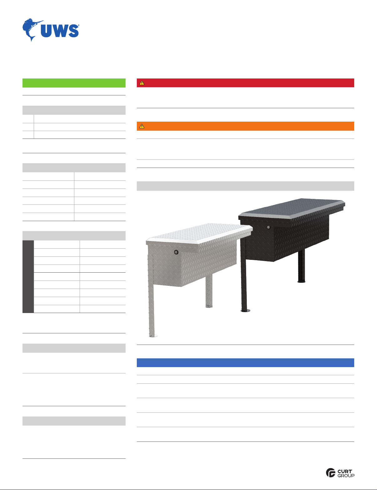
Representative Product Photos (your specific box may vary in style, size or finish)
Maintenance
For polished, gloss and other smooth
finishes, polish may be used to clear
small scratches and scuffs on the finish.
Mild automotive detergent may be used to
clean the product. Do not use dish detergent,
abrasive cleaners, abrasive pads, wire
brushes or other similar products that
may damage the finish.
DANGER
Danger of explosion. Do not use this product for storing or transporting flammables,
explosives, hazardous materials or hazardous waste, such as containers of gasoline,
solvents, gun powder, dynamite, propane tanks, acetylene tanks and cutting torches.
WARNING
Never exceed the vehicle manufacturer's recommended capacity.
This product can reduce the driver's ability to clearly see roadways, vehicular or pedestrian
traffic and other objects through the rear and side windows of the vehicle, which may cause
an accident. Extra precaution should be taken when driving a vehicle with this product.
Do not interfere with factory-installed safety equipment.
NOTICE
Before you begin installation, read all instructions thoroughly.
Proper tools will improve the quality of installation and reduce the time required.
To help prevent damage to the product or vehicle, refer to the torque
specifications when securing hardware during the installation process.
Do not use this product for purposes other than those
for which they were designed. Never modify this product.
Consult your dealer if you have any questions regarding
the installation, operation, use and limits of this product.
Treat or seal all fasteners and exposed metal in any
holes drilled in vehicle to prevent corrosion.
Product Registration and Warranty
CURT Group stands behind our products
with industry-leading warranties. Provide
feedback and help us to improve our
products by registering your purchase at:
warranty.curtgroup.com/surveys
INSTALLATION MANUAL LOW PROFILE TRUCK
SIDE TOOL BOX
Torque Specifications*
Metric
M6 bolt 3 ft-lbs.
M8 bolt 7 ft-lbs.
M10 bolt 16 ft-lbs.
M12 bolt 28 ft-lbs.
SAE
1/4" bolt 3 ft-lbs.
5/16" bolt 7 ft-lbs.
3/8" bolt 16 ft-lbs.
7/16" bolt 20 ft-lbs.
1/2" bolt 28 ft-lbs.
* Above specifications are general guidelines.
If purchasing hardware use the torque
specifications provided with that hardware.
UWSTA .COM •NEED ASSISTANCE? •833.387.7720 •RB •PAGE 2
Step 1
Place the tool box on the bed rails
and determine the best location.
WARNING
Before drilling into your truck bed, check under
your vehicle to ensure the drill location does not
puncture, cut or obstruct any brake or fuel fluid
lines, electrical wires, fuel tanks, etc. Precaution
must be taken that all fasteners near the fuel
tank do not create the possibility of fuel tank
puncture or other damage during a collision.
Step 4
Drill a minimum of two holes per leg.
A minimum of one bolt should be
used on each side of the legs.
Secure the legs to the tool box using one
bolt, two washers and one lock nut in each
drill location.
Note: For added security, the legs
may be bolted to the truck bed.
Step 2
Drill a minimum of two holes through
the tool box and bed rail.
Place a flat washer and bolt through each drill
hole. Secure using a washer and lock nut under
the bed rail. Fully tighten the hardware.
Step 3
Place the supplied legs on the corners of
the tool box that are fully inside the truck bed.
Use a square to ensure the legs are vertical
and at the appropriate height so they rest on
the truck bed.
WARNING
Before drilling into your truck bed, check under
your vehicle to ensure the drill location does not
puncture, cut or obstruct any brake or fuel fluid
lines, electrical wires, fuel tanks, etc. Precaution
must be taken that all fasteners near the fuel
tank do not create the possibility of fuel tank
puncture or other damage during a collision.
WARNING
Locate the gas spring prior to drilling
into the tool box. Do not drill in the gas
spring mount location.
UWSTA .COM •NEED ASSISTANCE? •833.387.7720 •RB •PAGE 3
Step 5
If desired, the lock can be moved to the
opposite end of the tool box. If you are not
moving the lock continue to step 11.
Drill out and remove the rivets securing the
lock bar guard in place and remove the guard.
Step 6
Remove the two screws securing the rotary
latch in place. Slide the rotary latch and lock
bar out of the lock bar support.
Remove the push nut and screw securing the
lock bar to the rotary latch. If the push nut is
not reusable a lock nut can be used instead.
Step 7
Remove the hole plug in the side of the
tool box. Using pliers or a similar tool,
loosen the nut securing the lock in place.
Remove the lock.
Step 8
Adjust the position on the lock cam so it will
not make contact with the lock bar in the
locked position, and it will make contact
with the lock bar in the unlocked position.
Reinstall the lock on the opposite end
of the tool box. Reinstall the lock plug.
UWSTA .COM •NEED ASSISTANCE? •833.387.7720 •RB •PAGE 4
Step 9
Refasten the lock bar to the rotary latch using
a screw and push nut on the opposite end.
Make sure the screw head is facing inward
towards the tool box to avoid interference.
Slide the lock bar into the lock bar support and
refasten the rotary latch to the tool box using
two screws and a screwdriver.
Step 11
CAUTION
Ensure all knobs, bolts, screws, straps and
locks are firmly secured before every trip.
Periodically re-tighten and inspect all components
for signs of wear, corrosion and fatigue.
With the truck side tool box installed, periodic
inspections should be performed to ensure
all mounting hardware remains tight.
To protect your investment, see the
'Maintenance' section on page 1.
Congratulations on the installation
of your new UWS truck side tool box.
Step 10
Check the operation of the lock and latch.
The striker pin may need to be adjusted.
Reattach the lock bar guard with rivets
or screws of the appropriate size.

This manual suits for next models

17

Other UWS Automobile Accessories manuals

UWS DS-18 User manual

UWS

UWS DS-18 User manual

UWS TRUCK FENDER TOOL BOX User manual

UWS

UWS TRUCK FENDER TOOL BOX User manual

UWS TBS-63-SL-LP-B User manual

UWS

UWS TBS-63-SL-LP-B User manual

UWS TRANSFER TANK User manual

UWS

UWS TRANSFER TANK User manual

Popular Automobile Accessories manuals by other brands

injen technology RD1482 user manual

injen technology

injen technology RD1482 user manual

AEM 21-5011 Installation guidelines

AEM

AEM 21-5011 Installation guidelines

Sprint Booster v3 Ultimate Control user guide

Sprint Booster

Sprint Booster v3 Ultimate Control user guide

Kuda-Phonebase 094020 Installation instruction

Kuda-Phonebase

Kuda-Phonebase 094020 Installation instruction

Webasto Sprinter Vancouver Standard manual

Webasto

Webasto Sprinter Vancouver Standard manual

CLAS OE 2046 manual

CLAS

CLAS OE 2046 manual

Mid America Motorworks 611-639 instruction sheet

Mid America Motorworks

Mid America Motorworks 611-639 instruction sheet

ZZ2 ZZAIR-PRO instruction manual

ZZ2

ZZ2 ZZAIR-PRO instruction manual

Thule 2075 parts manual

Thule

Thule 2075 parts manual

SuperATV WM-K-TRX4 installation instructions

SuperATV

SuperATV WM-K-TRX4 installation instructions

Menabo JUZA Fitting instructions

Menabo

Menabo JUZA Fitting instructions

Tronic TKHU 2 A1 operating instructions

Tronic

Tronic TKHU 2 A1 operating instructions

Global Industrial 298721 user manual

Global Industrial

Global Industrial 298721 user manual

JADO G840S user manual

JADO

JADO G840S user manual

Flash Cover MN001 installation manual

Flash Cover

Flash Cover MN001 installation manual

Yakima WheelFork 1032732 manual

Yakima

Yakima WheelFork 1032732 manual

AL-KO AKS 3004 Service information

AL-KO

AL-KO AKS 3004 Service information

Aries 2156001 installation manual

Aries

Aries 2156001 installation manual

manuals.online logo
manuals.online logoBrands
  • About & Mission
  • Contact us
  • Privacy Policy
  • Terms and Conditions

Copyright 2025 Manuals.Online. All Rights Reserved.