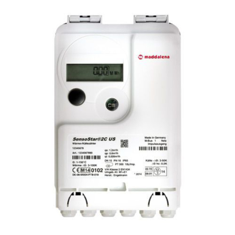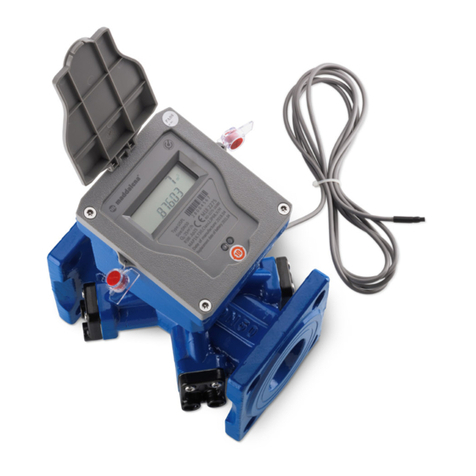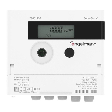
Energy Meter microCLIMA
Installation and Operating Instructions V. 1.03 October’06
microCLIMA
3. Mounting theTemperatureSensors
3.1. Installation in temperaturepocket
- PlacetheO-ring in themiddle
groove. Slide the sealing
screw nut upto the O-ring.
- Holding the screw nut in
place,insertthe sensor into
the ball valve and tighten the
screw nut.
3.2. Installation in a ballvalve
- Removethe blind cap orplug
and itsgasket. Checkthat all
surfacesare clean.
- PlacetheO-ring in the groove
closest to the tip ofthe
sensor. Slide the sealing
screw nut upto the O-ring.
- Holding the screw nut in
place,insertthe sensor into
the ball valve and tighten the
screw nut.
4. Start of Operation
- Slowlyopen the shut-off valves
- Checkfor leakage and proper functioning
- Clean the calculator
After confirming that the heat meter is functioning
properly,insert and tighten the sealing wires for
the temperature sensors and the heat meter itself.
When replacing ameter at the end of averification
periodnote the meter readings and the serial
numbersof the old andnew meters.
Please also checkthe following points:
• Is the heat meter the appropriate size?
• Is the heating system in operation?
• Are the shut-off valves open?
• Is the heating system clear(dirtfiltersnot
clogged)?
• Arethe temperaturesensorssealed with
wires(to avoid tampering)?
• Is the directionalarrow on the flow sensor
in the correct direction?
• Is a flow volume displayed?
• Is aplausible temperature difference dis-
played?
• For instrumentswith twoexternal temp-
eraturesensors, isthe forward flow sensor
(red) in the forward flow and the returnflow
sensor(blue)in return flowpipe?
• For instrumentswith abuilt-in return flow
temperaturesensor, is the flow sensor
mounted in thereturn flow?
5. TechnicalData
Type 0.6 1.5 2.5
Flow sensor
Nominal flow m3/h 0.6 1.5 2.5
Maximum flow m3/h 1.2 3.0 5.0
Nominalpressure bar 10
Low flow horizontal
threshold vertical l/h 3.5
4 7
7 10
10
Temperature range °C 15…90
Mounting position any
Calculator
Ambient temperature °C 5…55
Temperature range °C 1…130
Temperature difference K 3…100
Powersupply 3 V, Lithium
Operating life Years
(10+ 1 optional)
Datastorage E²PROM, daily
Display 8-digit
Infrared
M-bus (optional)
Interfaces
Pulse output
(optional)
Temperaturesensors
Type Platinum precision
resistor
Connection 2-wire technique
Diameter mm 5.0(optional 5.2)
Cable length m 1.5(optional 3.0)
6. The DisplaySet-up
The calculatorhasaliquid crystal displaywith8
digitsand special characters.The valuesthatcan
be shown are divided into three displayloops.
• main loop
• technician’s loop
• statistics loop
All dataisretrieved using the keynextto thedis-
play.The standard displayhasbeen set to perma-
nentlyshowthe totalheat quantityconsumed since
the meter wasput into operation.
At the start you areautomaticallyin the main loop.
Bypressingthe keylonger than 4seconds you
change to the next loop. Keep the keypressed
until youreach the desired information loop.
To change the informationdisplaywithin a loop,
simplygive ashort pressto the key.In thisway,
you can scan all the information in the loop.
Afteroneminuteof non-use, the displayreturns to
the total heat quantity, the standard display.


