V-GREAT VG-6728 User manual

1
VG-6728 Pulse Interface Installation Manual
(Ver1.2, Sep. 2020)
I Overview
II VG-6728 Digital Pulse Interface is designed to monitor and drive a fire-fighting equipment,
when received an order from FD&A control unit. Its principle and application is generally similar
to VG-6727 Digital Control Interface. The only difference is utilizing Pulse-drive method on
detachable equipment, such as Fire Valve, Solenoid Valve, Exhaust Fan, etc. This interface is
designed with dual-capacitors inside to provide instant energy for the activation of other
fire-fighting equipment, without need of extra power supply.
III Features
Distributed intelligent products, plug-in structure design.
With dual capacitor energy storage, and driving the equipment in a pulsed manner, the reliability is
improved.
There is no need to provide 24V operating power supply to the interface, which can reduce
construction costs.
Output terminal and the feedback terminal are provided with the function of line monitoring.
IV Technical Data
Operating voltage: DC18V-28V Standby current: ≤ 1mA
Output capacity: DC30V/2A
Acting time: 270mS. (time from activate to stop)
Temperature: -10℃~ +50℃
Humidity: ≤95%GH (40±2 ) without condensation℃
Status indication: When charging, both “Input” and “Output” indicators flash in a quick manner,
and the “Input” indicator flashes in a quick manner when fully charged; When activated, the
“Output” indicator is illuminating and the “Input” indicator is illuminating when receiving a
feedback signal; When there was fault on Output or Input, the corresponding indicator will flash in
a slow manner.
Loop wiring: Non-polarity
Maximum charging current: 4mA (when the energy of capacitors is down to zero, it is charged by
loop power);
Charging time: about 48s (the two lights flash in a quick manner when charging; the energy
storage voltage is 30V ± 2V when fully charged, and the input action monitoring light flashes
when fully charged)

2
Dimensions: 82mm×82mm×35.5mm (excluding base)
Transmission distance : ≤ 2,000m
Program: Electronic Addressing
Installation: Wall-mount, plug-in structure
Adapting base: VG-6613G
V Structure and Installation Dimensions
VI Wiring and Installation
Definitions of terminals:
Terminals (L1, L2): Loop Input terminal,
which is connected to the loop line (L+ and
L-) of the Digital Fire Alarm Panel as
non-polarity; it is also the terminal for
programmer;
Terminals (K1, K2): the positive and
negative activating the fire equipment, and
K1 and K2 can monitor the circuit fault;
Terminals (S1, S2): the input terminal of the
feedback signal from the fire equipment,
which receives the passive switching signal,
and monitors the feedback signal input line
for disconnection failure by detecting the
Figure (1) Dimensions Schematic
Loop Input terminal
Output terminal Input terminal
Installation
Up
Figure (2) Definition of terminals
3
3KΩ terminal resistance.
Settings of Jumper: “SI” put on Jumper
to open the function of line-fault check on
Input line, while take off the jumper to
close. “SO” put on Jumper to open the
function of line-fault check on Output line,
while take off the jumper to close.
Other functions of the interface set by using
VG-6537 Programmer: as shown in Table "1"
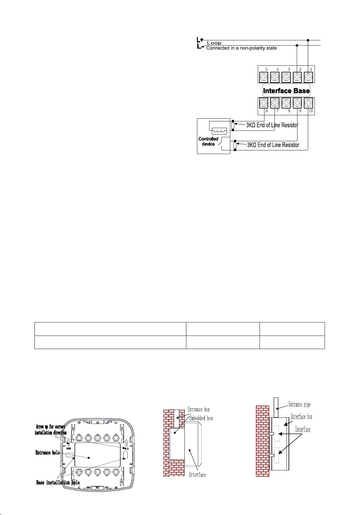
Engineering application passive output wiring scheme:
The wiring of the Base VB-6613G of VG-6728 Pulse Interface is shown in Figure (3);
The base terminals L1 and L2 connected to the loop as non-polarity.
The base terminals K1 and K2 connected to the passive terminals of the fire equipment.
The base terminals S1 and S2connected to the feedback of the fire equipment.
The EoL resistor 3KΩ is required on both the action and feedback terminals of the fire
equipment (if electro-magnetic type).
The interface is strictly forbidden to connect to the active type of fire equipment.
When there are 25 interfaces in the same loop, its front end should not be connected
with VG-6777 Isolate Interface, and if there are more than 50 interfaces in the same loop,
the front end shall be connected with VG-6781 Repeater Interface.
Table 1: Enter the following values after operating the 024 command of the VG-6537 Digital
Programmer
Output (interface power-on, state at reset) Input feedback Auto feedback
K2 and K1 are normally open 201 (default) 200
Construction and wiring requirements:
It is recommended to use ZG-GVS-2×1.0~1.5mm2 flame-retardant twisted-pair cable for the loop
wiring. If there are too many devices connected in the loop, it is suggested that the flame-retardant
twisted-pair cable no less than 1.00mm should be used. .
Installation:
Figure
(7) Interface
Installation Method
Figure (8) Interface
Installation Method II
Figure (3) Wiring diagram
4
Install the interface base in the position specified in the construction drawing. Please note that
the upward arrow on the interface base is the correct installation direction;
An Programmer is used to address the interface. Note: The bus devices in the same loop bus
should not have the same address code;
Install the interface firmly on the base, and
the installation is complete.
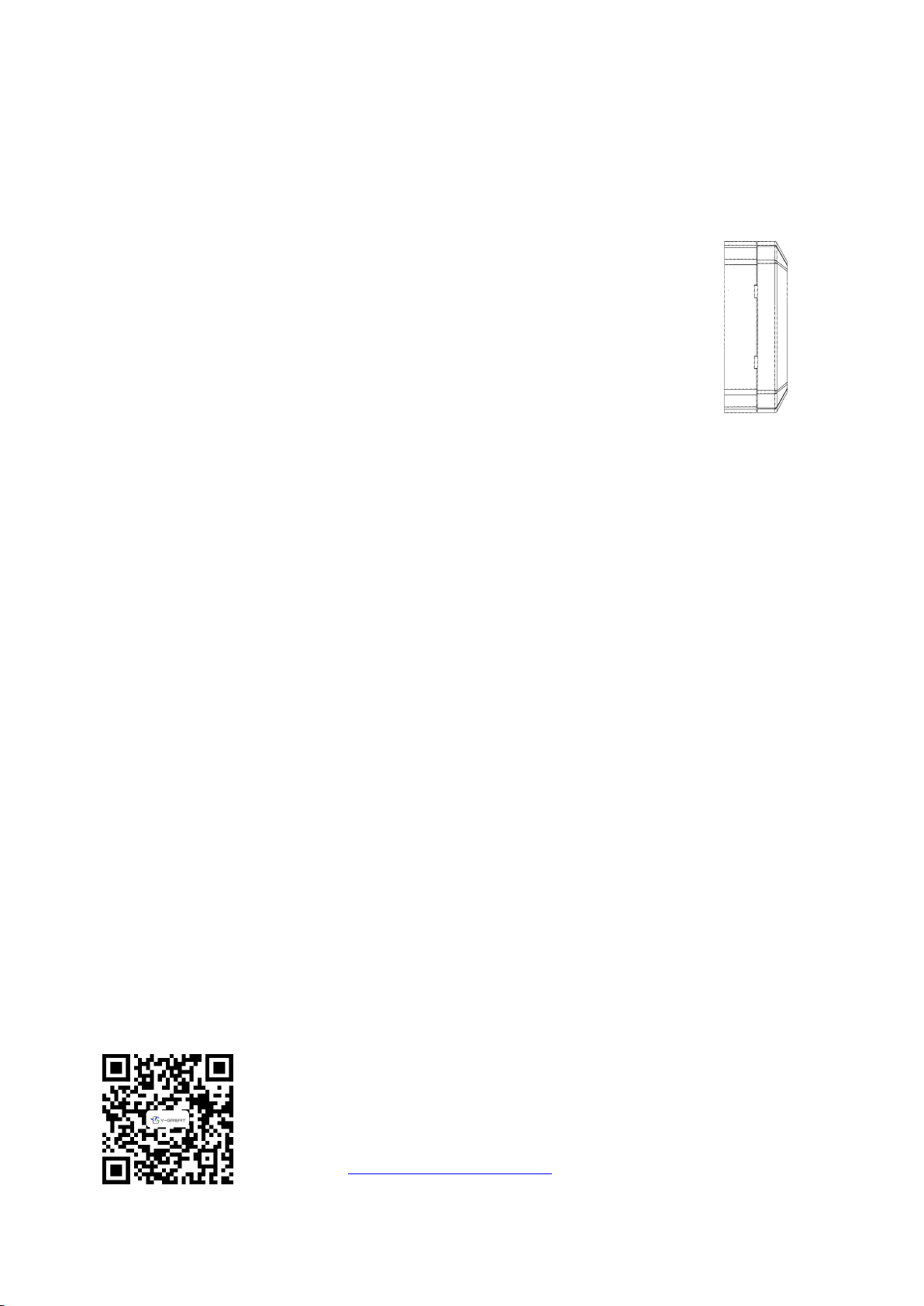
Disassembly of interface:
There are 2 openings for removing the interface on the two sides of
the joint of the interface and the base, respectively;
Insert a slotted screwdriver into the opening at an angle, and
gently pry the interface one by one to remove the interface.
For detailed steps and methods of addressing, refer to the VG-6537 Digital Programmer
Instruction Manual.
VII Handling and Storage
The transportation, handling, and storage of the Interface must be carried out in a packaged state. It
is necessary to handle in a gentle manner during loading and unloading to prevent collision damage.
The repeater should be stored in ventilated and dry places, and shall not be stored in the open.
VIII Precautions
In case that an interface failure is reported after long-term operation, it is necessary to first check
whether the interface has been damaged, or whether the installation position has changed
unexpectedly, and then consider other causes of the failure.
The staff on duty shall be proficient in the operating procedures of the equipment and disoperation is
not allowed.
The interface is a fire-fighting product. The on-duty and shift of duty system must be strictly
implemented during use, and the operation records must be maintained properly.
Functional tests should be performed on the interface every six months.
Company: V-GREAT GLOBAL CORPORATION
Add.: Second Floor, Capital City, Independence Avenue,
P.O. Box 1008, Victoria, Mahe, Seychelles
Web:http://www.vgreatglobal.com Email: tech@vgreatglobal.com
Table of contents
Other V-GREAT Recording Equipment manuals


