Installation instructions
Range hood
Operating mode: Extraction/recirculation
DSMS
1030019-R04
10/05/2017
2
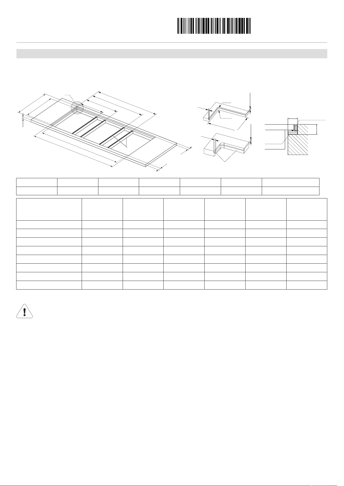
Extraction mode
The extracted air must not be fed into a chimney which is used for exhausting fumes from appliances burning gas or
other fuels.
Observe the local fire regulations.
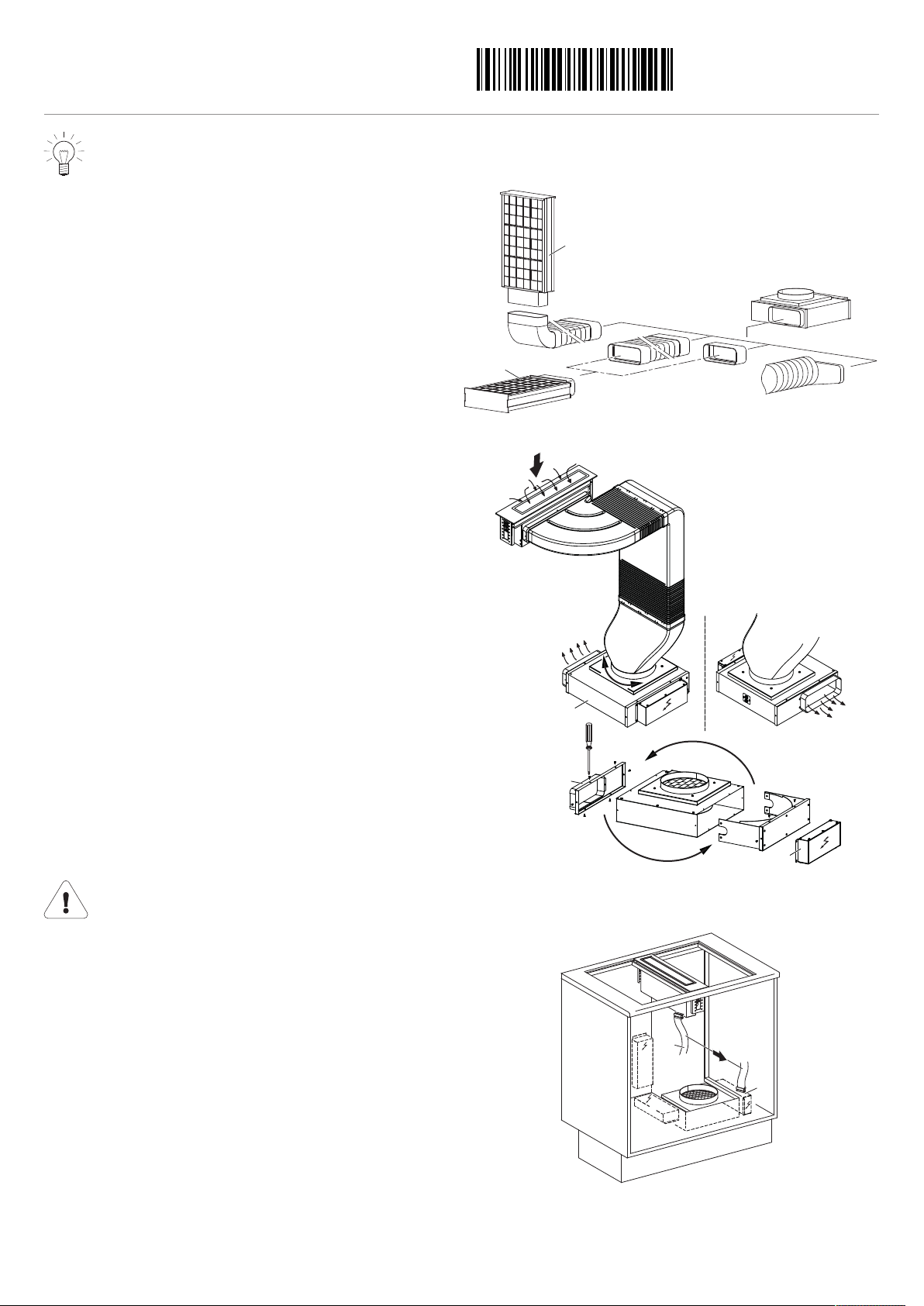
Recirculation mode
Dedicated accessories that need to be fitted to operate the appliance in the recirculation mode: 1012161 recirculation
box with activated charcoal filters!
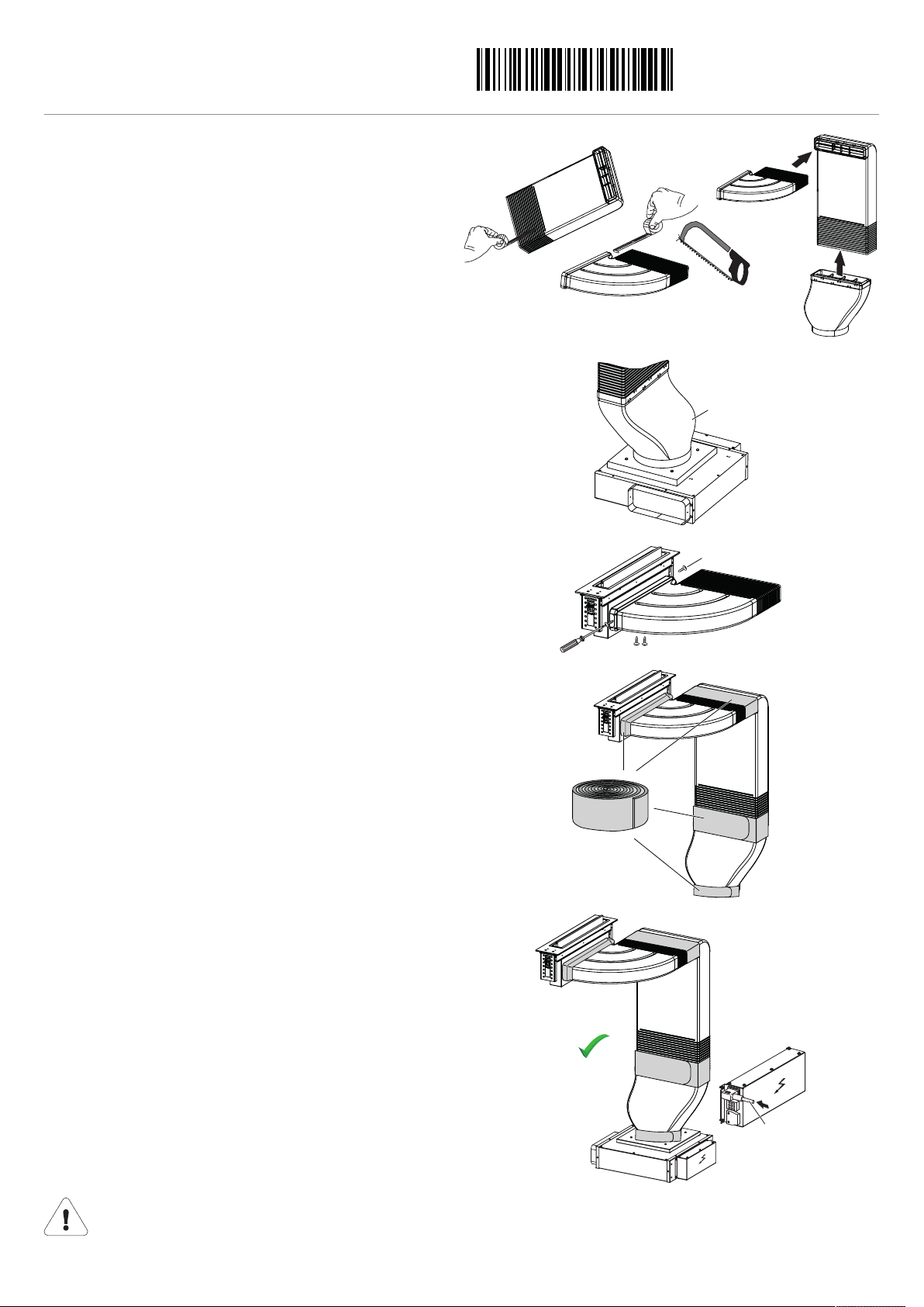
▪Install the recirculation box with activated charcoal filter in the base or adjacent cabinet.
▪If the recirculation box is not equipped with activated charcoal filters, these have to be ordered and installed before using the
appliance for the first time.
The ventilation outlet must not be covered during operation.
Electrical connections
Electrical connections must be carried out by qualified personnel in accordance with the guidelines and standards
for low-voltage installations and the specifications of the local electricity supply companies.
A plug-in appliance may only be connected to a socket outlet with earthing contact, installed according to specifications.
An all-pole mains isolating device with 3 mm contact opening should be provided in the house wiring system. Switches,
plug and socket devices, circuit breakers and fusible cut-outs which are accessible after installation and which have all-
poles switching are permissible as isolating devices. Effective earthing and separately installed neutral and earth con-
ductors ensure safe and fault-free operation. After installation, live parts and cables with basic insulation must not be ac-
cessible. Check old installations.
▸The appliance is designed for use up to a max. altitude of 2000 m above sea level.
▸Refer to the identification plate for information on the required mains voltage, current type and fuse protection.
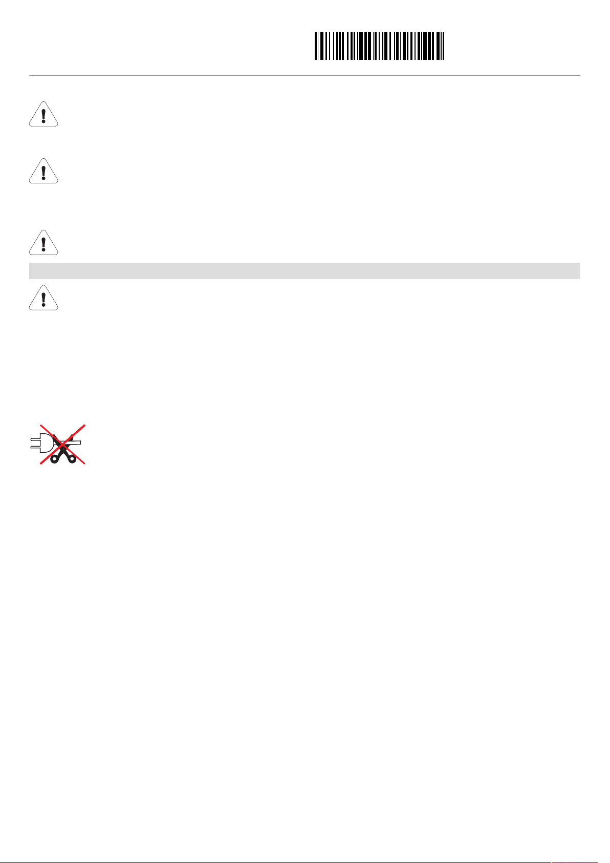
The mains plug must not be cut off.