DEUTSCH
BESCHREIBUNG DER VORRICHTUNG
Der Sensor SENSIVA-PLUS kann 8 verschiedene Sendecodes
auswählen, d.h. es können 8 Sensorenpaare gleichzeitig installiert
werden, ohne dass die Gefahr von Störungen besteht.
Merkmale:
• Auf der Horizontalachse bis zu 180° schwenkbar, auf der
Vertikalachse bis zu 30°.
• Automatische Verzögerung der Signalerfassung bei Schnee,
um ein ungewolltes Ansprechen bei Schneefall zu vermeiden.
• Einstellung der Reichweite auf zwei Stufen.
• Led für eine vereinfachte Systemeinstellung.
WANDMONTAGE (Abb.1)
Fur eine korrekte Installation aufmerksam folgende Hinweise
befolgen:
• Die zur Installation vorgesehenen Punkte bestimmen und
dabei berucksichtigen, dass die Fotozellen auf einer linearen
und ebenen Oberfläche befestigt werden mussen.
mACHTUNG: die Fotozellen so positionieren, dass sich
der Empfänger RX der Sonne gegenuber befindet.
• Den Verlauf der Kabeldurchgänge fur die Stromversorgung
festlegen.
• Das Gehäuse der Fotozelle öffnen und die Basis A zum
Anreißen der Befestigungslöcher benutzen.
• Die Basis befestigen und die Anschlusse am Klemmenbrett
vornehmen.
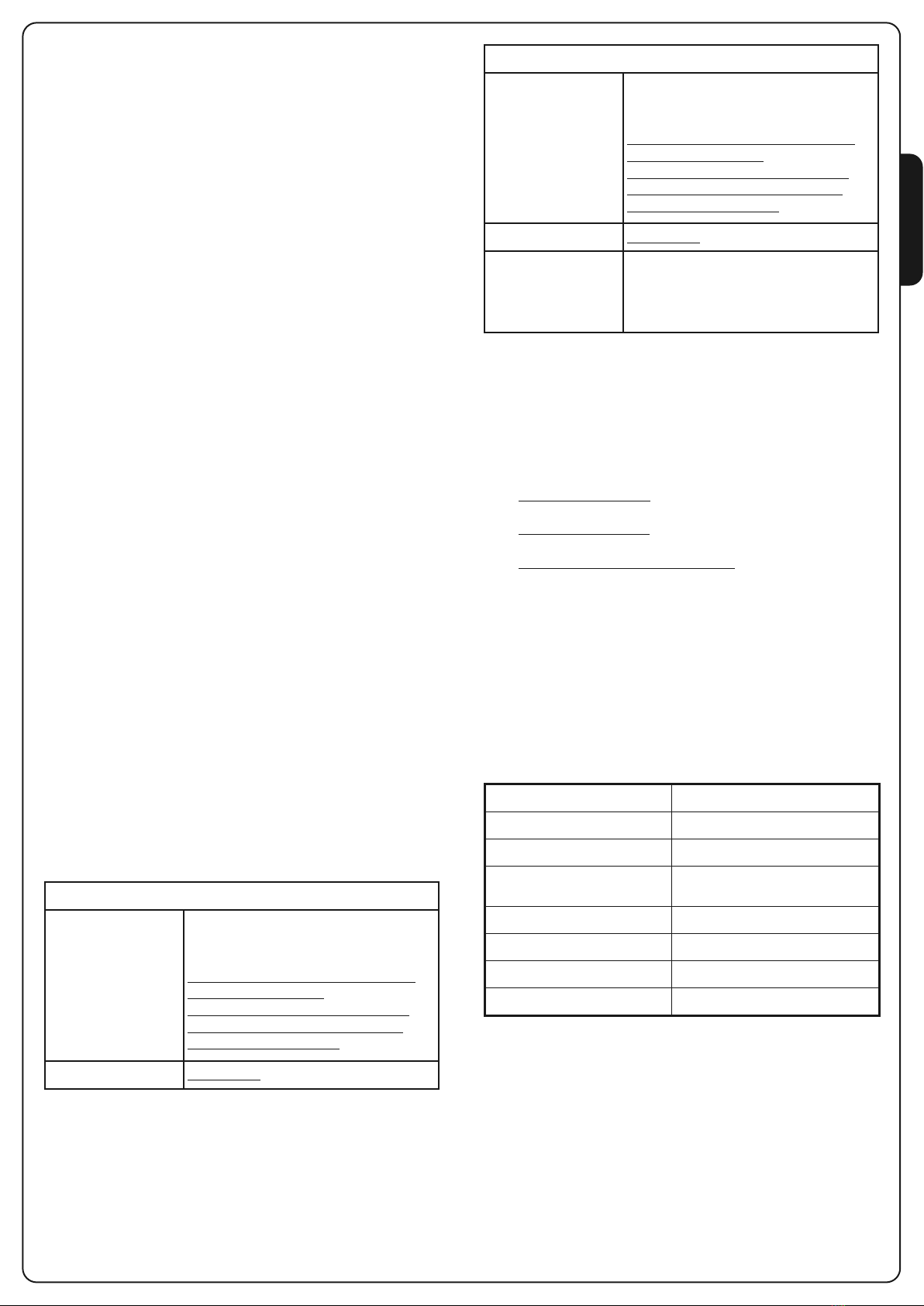
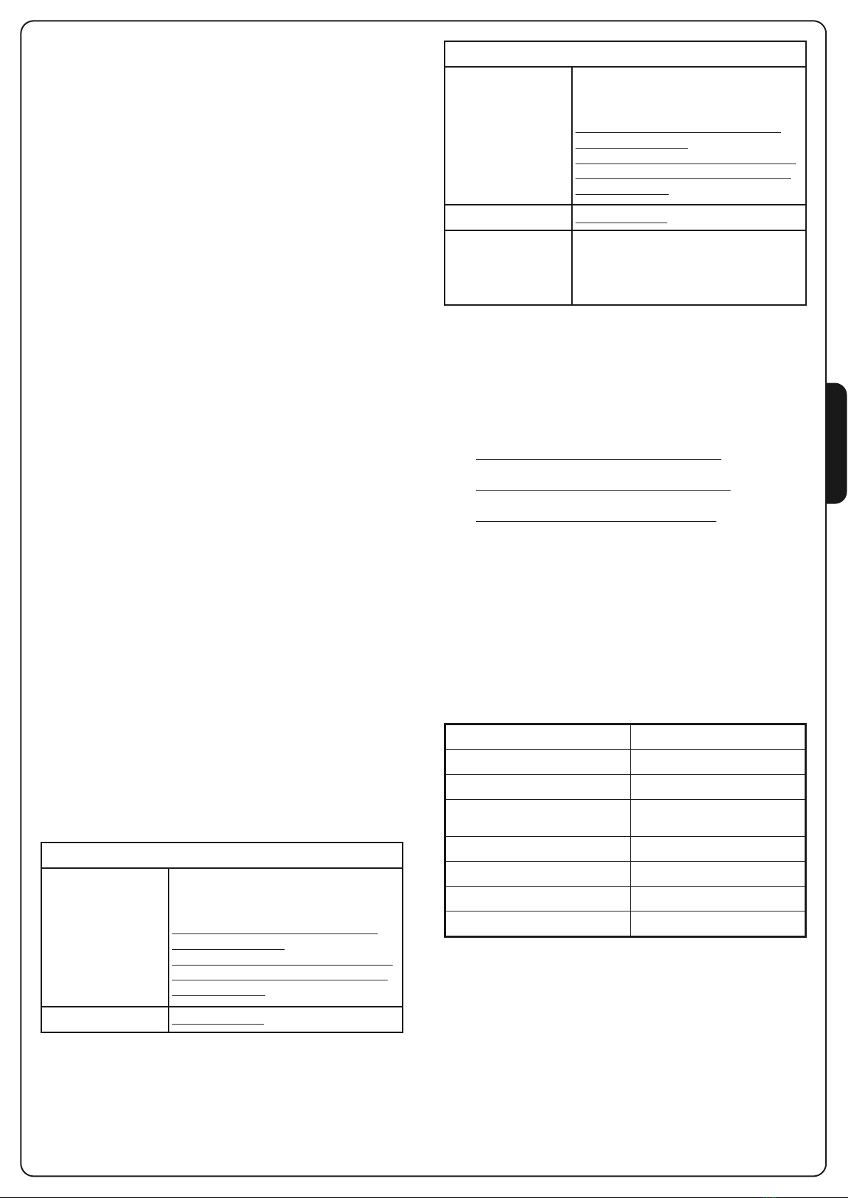
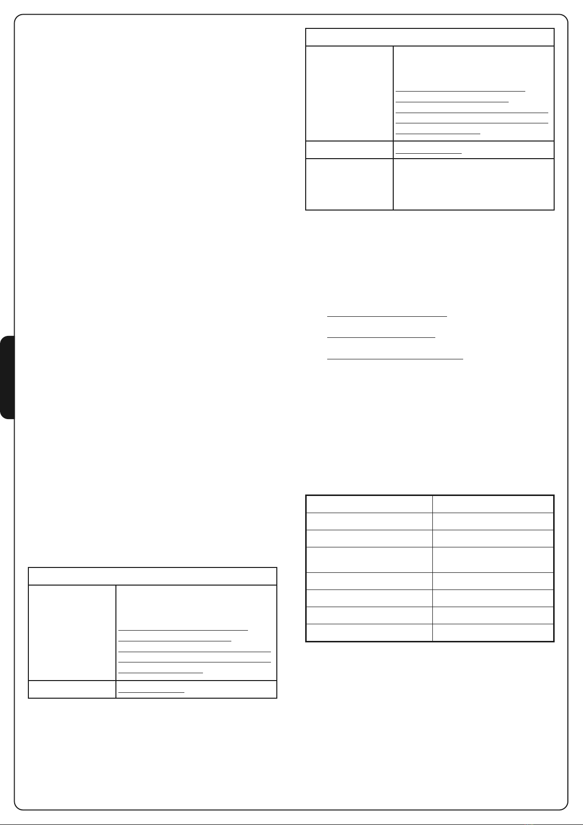
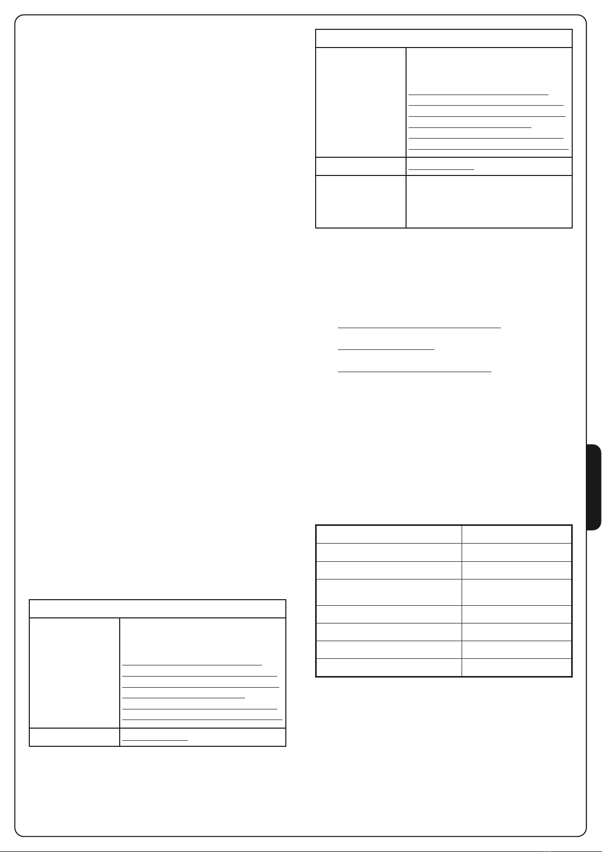
STROMANSCHLÜSSE
SENDER (TX)
1Stromversorgung (+)
2Stromversorgung (-)
EM FÄNGER (RX)
1Stromversorgung (+)
2Stromversorgung (-)
3 - 4 Relaisausgang
- Relais-Ausgang mit Öffnerkontakt - 2 Stellung A
- Relais-Ausgang mit Schließerkontakt - 2 Stellung B
DI -SWITCHES UND JUM ER (Abb. 3)
Der Dip-switch und die umper, die in den elektronischen
Schaltkreisen der Sensoren vorhanden sind, dienen zur
Einstellung der Systemfunktionen.
SENDER (TX)
DI -SWITCH 1 - 2 - 3
Sendecode: Durch die Eingabe
verschiedener Kombinationen können bis
zu 8 verschiedene Codes erstellt werden.
TX und RX ein und desselben Paares
müssen die gleiche Kombination haben.
Mehrere Paare, die gemeinsam installiert
sind, müssen mit verschiedenen
Kombinationen versehen werden, damit
zwischen ihnen keine Störungen auftreten
DI -SWITCH 4 Auf ON behalten
EINSTELLUNG
Nach der Installation prufen, ob das System korrekt funktioniert:
1. Sicherstellen, dass sich kein fester Gegenstand zwischen
Sender und Empfänger befindet.
2. System mit Strom versorgen:
- Das LED des Empfängers ist ausgeschaltet: Fotozelle ist
nicht zentriert. Zentrierung vornehmen
- Das LED ist eingeschaltet: die Fotozelle ist zentriert, zu
Punkt 3 ubergehen.
- Die Led des Empfängers blinkt langsam: das Signal ist zu
schwach. Entweder die Ausrichtung verbessern
3. Abdeckung Bauf die Fotozelle setzen und auf korrekten
Betrieb prufen, ohne den selbstklebenden Abschwächungsfilter
Czu entfernen (der Filter simuliert ungunstige meteorologische
Bedingungen wie Regen, Nebel usw.)
4. Danach den Abschwächungsfilter entfernen.
5. Mehrmals den Infrarotstrahl unterbrechen: das LED des
Empfängers muss sich ausschalten und das Relais muss
umschalten.
TECHNISCHE EIGENSCHAFTEN
Optische Leistung 20 m
Masse 115x41x38 mm
Stromversorgung (VIN - GND) 12÷24 Vac / 12÷36 Vdc
Signal Moduliertes Infrarot
2 KHz l= 940 nm
Leistung Kontakte Relais Empfänger 1A max 30 VDC
Stromaufnahme (VIN = 24Vdc) TX 15 mA RX 20 mA
Betriebstemperatur -20° + 60° C
Schutzart IP54
EM FÄNGER (RX)
DI -SWITCH 1 - 2 - 3
Sendecode: Durch die Eingabe
verschiedener Kombinationen können bis
zu 8 verschiedene Codes erstellt werden.
TX und RX ein und desselben Paares
müssen die gleiche Kombination haben.
Mehrere Paare, die gemeinsam installiert
sind, müssen mit verschiedenen
Kombinationen versehen werden, damit
zwischen ihnen keine Störungen auftreten
DI -SWITCH 4 Auf ON behalten
JUM ER J2
Stellung A - Relais-Ausgang mit
Öffnerkontakt
Stellung B - Relais-Ausgang mit
Schließerkontakt