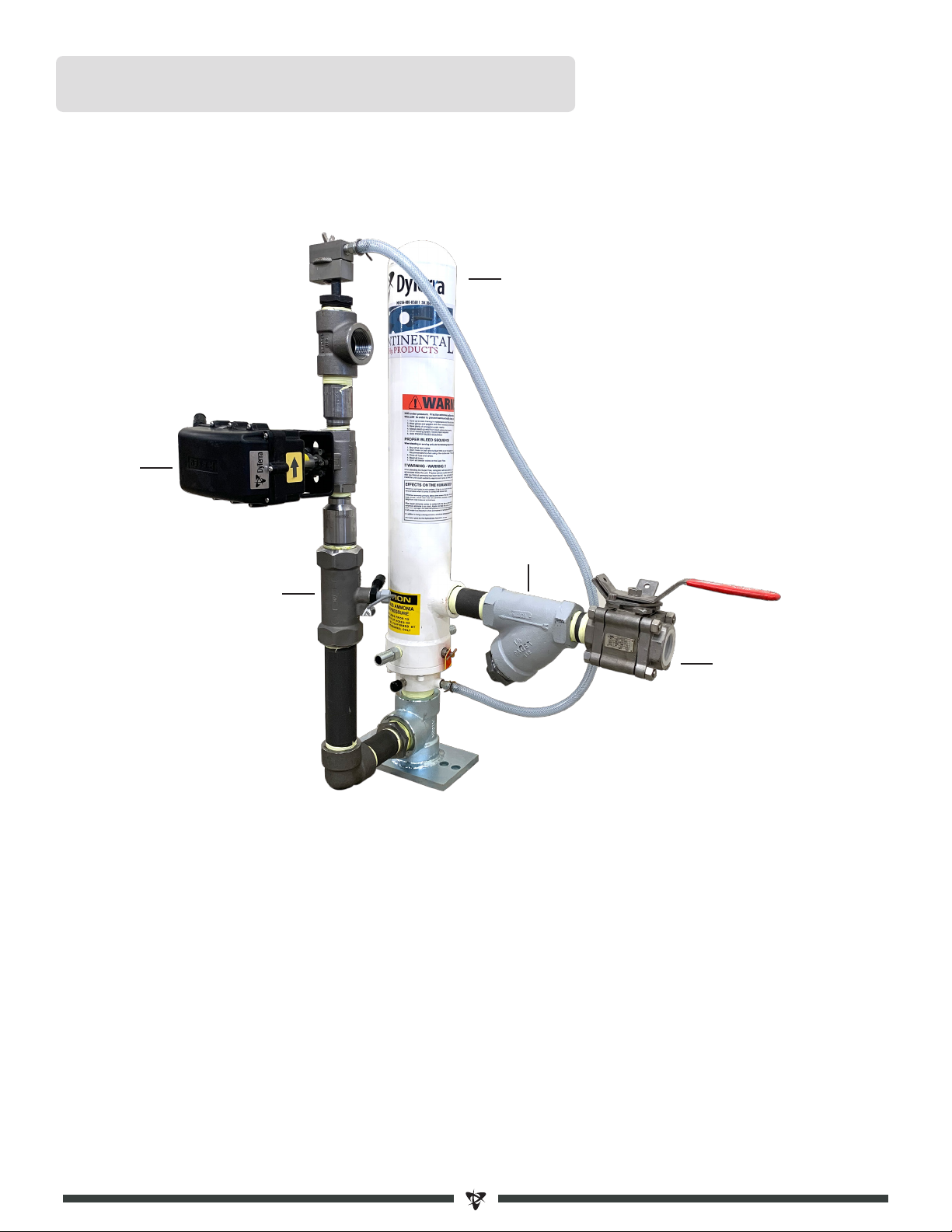
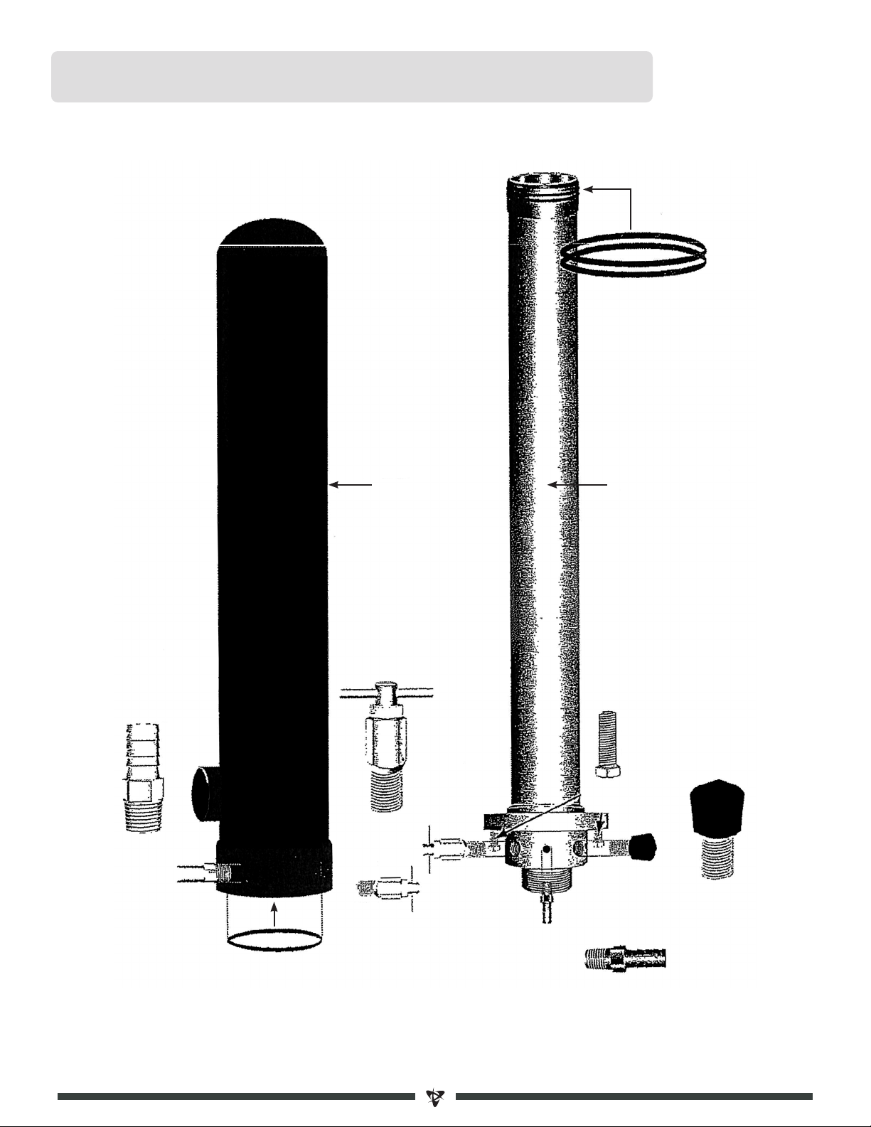
DyTerra NH3 User manual

NH3 KIT
ASSEMBLY GUIDE
MIINST
NH3 KIT GUIDE

www.dyterra.com | info@dyterra.com
MARLIN HEFFLEY
306-244-4448
JEREMY SCHMIDT
306-244-4448
The DyTerra NH3 Kit Assembly Guide is also available online at www.dyterra.com/kits
The DyTerra NH3 Kit Assembly Guide covers all of our available NH3 kits.
Please locate your item in the table of contents and disregard any
items that do not apply to the kit you have purchased.
If you need assistance, or have any questions that are not
answered in this guide, please give us a call.
We’ve done our best to ensure the accuracy of this guide. It is intended to assist you in installing various
manufacturer’s components. In no event will DyTerra be liable to any party for any direct, indirect,
special or other consequential damages related to the use of this Assembly Guide.
DISCLAIMER

SETTING UP AN NH3 KIT............................................................................................................. 2
CONTINENTAL SUPERFLOW ........................................................................................................ 4
CONTINENTAL COOLER BREAKDOWN ........................................................................................... 5
RAVEN COOLER ......................................................................................................................... 6
CONTINENTAL METER SETUP ...................................................................................................... 7
MVD MANIFOLD - NO SECTION CONTROL ...................................................................................... 8
MVD MANIFOLD - SECTION CONTROL ........................................................................................... 9
JOHN BLUE MANIFOLD - NO SECTION CONTROL............................................................................10
JOHN BLUE MANIFOLD - SECTION CONTROL.................................................................................11
JOHN BLUE SPLITTER ...............................................................................................................12
CHECK VALVE - SECTION CONTROL ONLY .....................................................................................13
HIGH FLOW BREAKAWAY KIT.....................................................................................................14
HOSE LENGTHS ........................................................................................................................15
RAVEN 440 CONSOLE ................................................................................................................16
RAVEN TROUBLESHOOTING........................................................................................................18
DICKEY-JOHN TROUBLESHOOTING ..............................................................................................20
DICKEY-JOHN COMMON REPLACEMENT PARTS.............................................................................21
RAVEN VALVES AND ACTUATORS ................................................................................................23
TABLE OF CONTENTS

STEP 1 SUPERCOOLER
Assemble the cooler according to the manufacturer’s instructions. Once the
cooler is assembled, measure where it will best fit on your applicator and
bolt it down. Run the supplied wiring harnesses to the tractor. Keep in mind
where the applicator folds up.
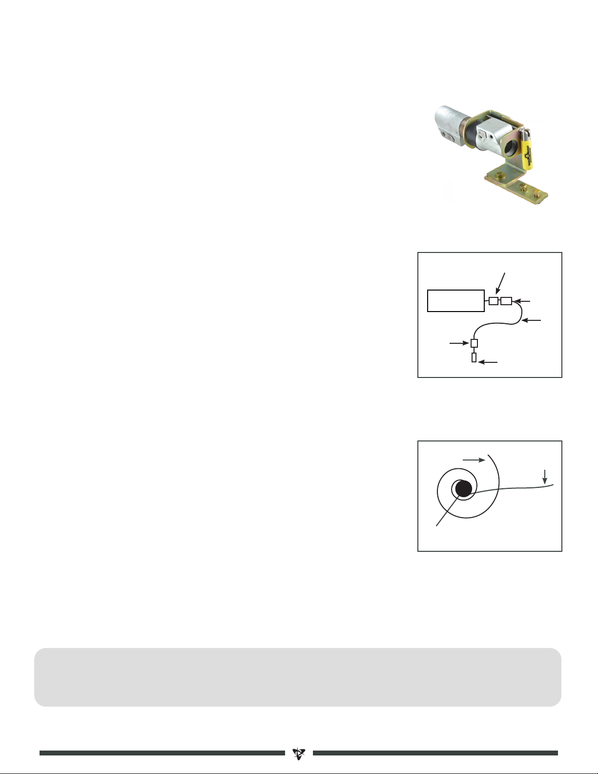
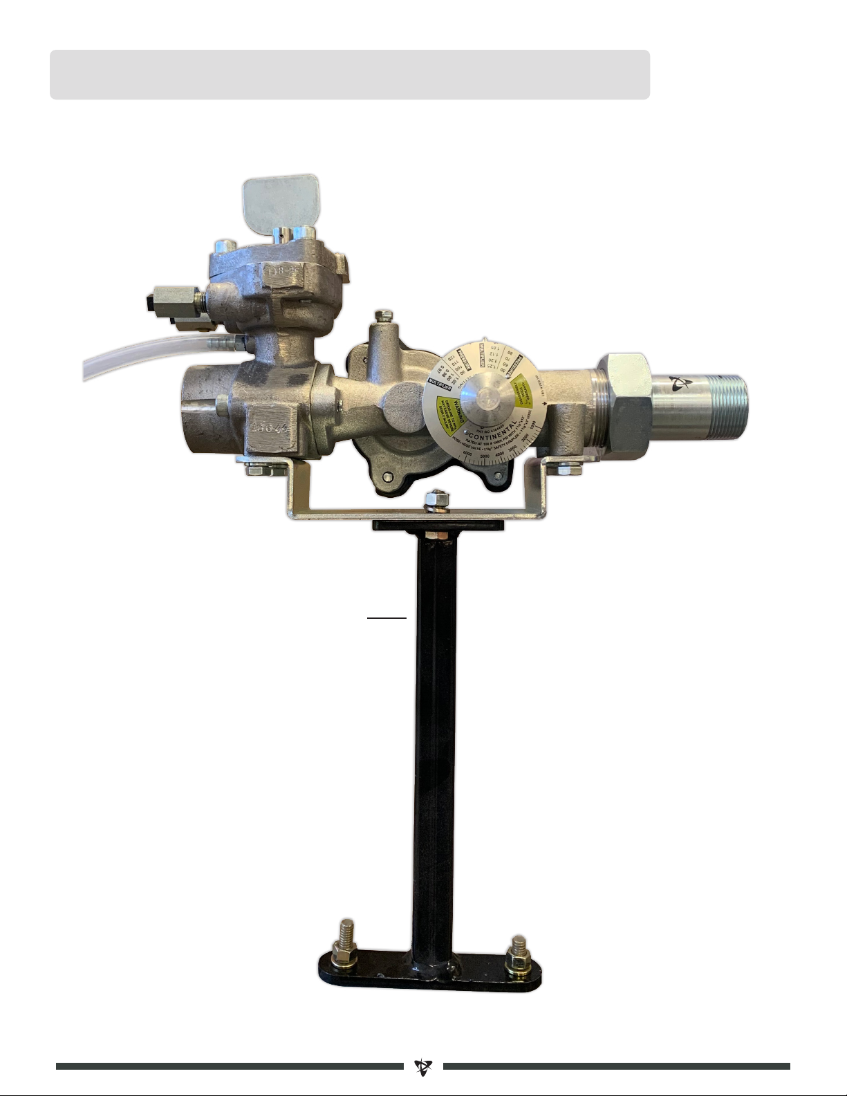
STEP 2 SPLITTER
Thread the 1 ¼"x 6" pipe nipple into the 1 ¼" tee coming off of the cooler. The
splitter should be level and facing upright. If you want to mount the splitter
remotely, use the John Blue Splitter Stand.
STEP 3 MANIFOLDS
Thread the manifolds onto the manifold stands using the 1" nipple and a 1" tee.
Then thread in the hosebarbs. Once the manifolds are assembled they can be
attached to your applicator. Mount the pressure gauges so you can see them
from the tractor cab (if possible). When running lines, keep in mind how many
folds your applicator has, and where it folds up.
STEP 4 HOSE FROM SPLITTER TO MANIFOLDS
Cut a piece of hose to fit between the splitter and the furthest manifold.
According to the manifold assembly instructions, all other hoses should be
cut the same length as your longest hose. Failing to do so will distribute NH3
unevenly to each manifold, which will result in streaking.
SETTING UP AN NH3 KIT
2
Q. Can I plug my manifold ports?
A. Yes. If you have a John Blue Impellicone or Continental MVD manifold you can plug unused manifold outlets.
Be sure to plug an even amount of outlets per manifold if possible. Space plugs evenly on manifold to
ensure even distribution.
FAQ

STEP 6 HOSE -BREAKAWAY TO COOLER
Measure and cut the NH3 hose to fit between the breakaway and cooler. Our kits are
supplied with a 15ft length. Try to run the hose as straight as possible. If this is not
possible, use a gentle curve in the hose. Using a 45 or 90 degree fitting will restrict
flow and decrease maximum rates.
An optional ball valve can be added after the breakaway which will eliminate the
need to bleed down your whole hose when changing tanks in the field.
STEP 7 MANIFOLD HOSES
Cut and measure the longest length of manifold hose. All hoses should be cut the
same length for maximum accuracy. Failing to do so will distribute NH3 unevenly
to each manifold, which will result in streaking. Connect each manifold outlet to a
shank or boot.
STEP 5 BREAKAWAY KIT
Install the breakaway bracket at the back of your cultivator according to the
manufacturer’s instructions inside the box. In a vice, thread bleeders, hydrostat,
hosebarb and ACME adapter into the breakaway and attach it to the bracket. Make
sure the breakaway moves freely up/down and left/right.
COOLER
Hose
Strainer
Breakaway
Shortest Run
Same Length
Longest Run
Manifold
3
Optional Ball
Valve
RAVEN Ball Valve
Q. Why are people using smaller EVA hose from their manifolds to the ground? What are the advantages?
A. Smaller diameter EVA hose will increase the pressure in the lines. This will keep the NH3 liquid for longer
which will cause less frost. The increase in pressure will also prevent tubes from plugging up.
FAQ

CONTINENTAL SUPERFLOW WITH RAVEN VALVES AND FLOWMETER
Part Part Number
AContinental Superflow Cooler CTA-SF-3000GT
BRaven Fast Valve 1" RV1-063-0173-878
CRaven Flowmeter RV1-063-0173-867
D1½" Strainer MIPAGET24-100
E1½" Ball Valve BVSS243
CONTINENTAL SUPERFLOW
4
A
B
C
E
D

CONTINENTAL COOLER BREAKDOWN
5
O-Ring
included in CTA-SF-RK
A-SF-2A-SF-1
Base Barb
#7550(4)
O-Ring
included in CTA-SF-RK
Bleeder
Valve
#A-411 (2)
Bolt
#09-375-125 (4)
Screw
#A-400-250
Hose Barb
#A-1132

RAVEN COOLER
6
Part Part Number
AVortex Cooler RV1-063-0173-663
BRAVEN Flowmeter RV1-063-0173-869
CRAVEN Flowmeter Sensor RV1-063-0171-669
DGruvlock Coupling RV1-333-0006-032
E0-400 PSI Liquid Gauge PGA4004L
FRAVEN Control Valve RV1-117-0171-706
GRAVEN On-Off Valve RV1-117-0171-705
HStrainer Kit RVS08
*If RAVEN has optional single fast valve RV1-117-0171-707:
EF*G
A H
2-valve cooler shown below
C
BD

CONTINENTAL B-9500 METER SETUP
7
A
CTB-9500-B
B
MICMS24

Gauge
Product In
King Nipple
MVD Manifold
Product Out
Stand
4
HELPFUL POINTERS
!
· Use thread tape and thread sealant when installing the king nipple
MVD MANIFOLD
NO SECTION CONTROL
8

Gauge
Product In
MVD Manifold
Product Out
Stand
Hoseclamp
On/Off
Valve
9
Q. Where should I mount my section on/off valves? Why?
A. Mounting your section on/off valves at the manifold ensures a quicker on/off response time for each
section. If you mount the on/off valves at the splitter, it will take longer for product in the lines to get to the
ground when turning that section on, and will allow more product to flow to the ground when turning that
section off.
FAQ
HELPFUL POINTERS
!
· Use thread tape and thread sealant when installing connecting plumbing
MVD MANIFOLD
SECTION CONTROL

Gauge
Impellicone Manifold
Product In Tee
6” Nipple
Stand
Product Out
King Nipple
10
HELPFUL POINTERS
!
· Use thread tape and thread sealant when installing connecting plumbing
· Use thread sealant when installing ¼” plumbing and hosebarbs
JOHN BLUE MANIFOLD
NO SECTION CONTROL

Pressure
Gauge
Impellicone Manifold
Tee
6” Nipple
Stand
Product Out
4” Nipple
Hoseclamp
On/Off
Valve
11
Q. Where should I mount my section on/off valves? Why?
A. Mounting your section on/off valves at the manifold ensures a quicker on/off response time for each
section. If you mount the on/off valves at the splitter, it will take longer for product in the lines to get to the
ground when turning that section on, and will allow more product to flow to the ground when turning that
section off.
FAQ
HELPFUL POINTERS
!
· Use thread tape and thread sealant when installing connecting plumbing
· Use thread sealant when installing ¼” plumbing and hosebarbs
MVD MANIFOLD
SECTION CONTROL

COOLER MOUNT
The splitter can be mounted directly on an NH3 cooler.
STAND MOUNT
A splitter stand kit is available if a cooler mount is not
possible.
Part Number: KTJBSSM
HELPFUL POINTERS
!
· Splitter must be mounted upright · Splitter goes directly after the cooler
· Outlets can be plugged · Use teflon tape and pipe sealant to assemble plumbing
1" Plug
6" Nipple
1¼” Tee
Splitter
6" Nipple
Product In
Splitter
Splitter stand
Product Out
to Manifolds
Product Out
to Manifolds
Product In
12
Q. Do hoses from the manifolds to the ground have to be uniform in length?
A. Yes. Failing to do so will distribute NH3 unevenly to each run, which will result in streaking.
Q. Can I plug my splitter ports?
A. Yes. If you have a John Blue Impellicone splitter you can plug unused outlets.
FAQ
JOHN BLUE SPLITTER

13
HELPFUL POINTERS
!
· A check valve is required to keep hoses charged when all sections are shut off
Q. Why does my Raven Accuflow have 2 valves? Why is this advantageous?
A. The first valve is a control valve which regulates what rate you are applying NH3 at. The second valve is
an on/off valve that allows you to quickly stop or start applying NH3. The advantage of having two valves is
that when you turn the system off or on, the valve that controls your rate does not move, and will not have
to “search” for the desired rate you have programmed into your field computer.
FAQ
CHECK VALVE
SECTION CONTROL ONLY

EZ Bracket
Flo Max
Breakaway
14
1 ¼" FLO MAX
Part #STFM126K
1¼" EZ Bracket
Part #STFM126-1500
Repair Kit 1¼"
Part #STFM125-0022DY
Plunger Kit 1¼"
STFM125-0023
1 ½" FLO MAX w/Bracket
Part #STFM150K
Repair Kit 1½"
Part #STFM150-0022
Plunger Kit 1½"
STFM150-0023
1 ¼" CONTINENTAL
WITH BRACKET
Part #CTB-SWV-125-D
Repair Kit
Part #CTA-SWV125150-RK
(o-rings)
Rebuild
CTA-SWV125150-RBK
1 ½" CONTINENTAL
WITH BRACKET
Part #CTB-SWV-150-D
Repair Kit
Part #CTA-SWV125150-RK
(o-rings)
Rebuild
CTA-SWV125150-RBK
CONTINENTAL BREAKAWAY
FLO MAX BREAKAWAY
HIGH FLOW BREAKAWAY

3 MANIFOLD SETUP
4 MANIFOLD AND UP SETUP
FOR MAXIMUM ACCURACY, KEEP ALL HOSES BETWEEN
SPLITTER & MANIFOLDS EQUAL LENGTH
NOTE: Hoses from the manifolds to the ground should also be the same length.
15
HOSE LENGTHS

QUICK SET-UP GUIDE
Note: A tutorial also available on DyTerra’s YouTube Channel
When the console is powered up for the first time it will flash CAL and US VOLUME PER ACRE. This means the console
must be programmed before operation.
1. To begin programming, ENTER to accept US VOLUME.
2. Display will now flash SP1-WHEEL DRIVE
a) Press the CE button, display will now show SP2-RADAR SPEED SENSOR. ENTER to accept SP2.
3. Display will now flash C-CD-STANDARD VALVE
a) If you have a 2 valve system (Tagged #2123 on the valve) then ENTER to accept standard valve
b) If you have a single FAST VALVE (Tagged #743 on the valve) then press CE button until you come to C-FC-FAST
CLOSE VALVE and ENTER to accept.
4. Display will now flash CAL SELF TEST 0.0. Leave this as-is for now.
NOTE: FOR THE FOLLOWING CALIBRATION SETTINGS YOU WILL NEED TO DEPRESS THE KEY IN WHICH YOU WANT TO
ENTER DATA, FOLLOWED BY ENTER, FOLLOWED BY THE NUMBER YOU WISH TO ENTER, FINALLY FOLLOWED BY ENTER
AGAIN TO SAVE.
5. Next press BOOM 1 CAL button and then ENTER and then enter the width of your applicator in INCHES (i.e.: 720” for
60ft.). ENTER to save.
6. Boom 2 and 3 width should both be zero, if they are not, then enter 0 for both.
7. Press SPEED CAL button then ENTER, then enter a speed calibration number, then ENTER.
NOTE: For Raven Phoenix 10 GPS Sensor, use Cal #785 and for Raven Radar Gun use #586.
a) If your Raven console speed does not match up with your actual tractor speed or you are using a third party speed
sensor, you can just increase or decrease the Cal number until they match.
8. Press METER CAL button then ENTER, then enter the calibration number from the flow meter, then ENTER.
a) The Meter Cal number is on a grey tag located on the flow meter under the Raven cooler. It will have a number
(i.e.: 169/lbsN) on it. This is the number you use. NOTE: DO NOT USE LIQUID OR LITRES number.
b) This is also the number you can change if you find you are over applying or under applying. To do this, take your
desired application rate divided by the rate you applied and multiply by the flow meter number
(i.e.: 100lbs / 90lbs x169 = 187 as new number).
9. Press VALVE CAL button then ENTER and enter your calibration number then ENTER.
a) Your Valve Cal number is on the valve motor. For a standard two-valve system the number is 2123 and for a single
fast valve setup it’s 743.
10. Press RATE 1 CAL button then ENTER, then enter desired lbs. of N to be applied (should be a rate you typically apply at,
i.e. 100 lbs.) then ENTER.
11. Press RATE 2 CAL button then ENTER then enter Rate 2 desired lbs. of N to be applied then ENTER. This provides the
ability to switch to a higher or lower application rate on the fly. IMPORTANT NOTE: You must enter a number in RATE 2
to complete calibration process.
16
RAVEN 440 CONSOLE

12. It should now be displaying RATE 00 and programing is complete. If not, go back to STEP 5 and begin again.
13. If an error is made in steps 1 to 3 you can fix it two ways.
Option 1: Press and hold SELF TEST until it cycles through all the settings and stops. The screen will say ‘UNITS US’
(takes about 15-20 seconds).
ENTER to advance to the setting you want to change. Press CE to change the value. ENTER to finish. Repeat for any
other changes needed. This method will save you from reprogramming all the calibration setting again.
Option 2: Factory Reset. (Caution: This which will also wipe out all the calibration settings you just entered.) This is
done by turning the power switch OFF then depress and hold the CE button while turning the power switch back ON.
Program all settings again.
14. Self-Test Feature
a) Self-test allows speed simulation for testing the system while the machine is not moving. This is done by pressing
SELF TEST then ENTER then desired speed (5.0mph) then ENTER. The system will also clear itself when the tractor
begins to move.
Additional: To learn about other settings like the SELF TEST and AUTOMATIC RATE +/- please see pages 18 and 19 in
the 440 console manual.
Also NH3 Calibration setting for the Valve Cal, Meter Cal, Speed Cal, Boom Cal, are all found in the Installation and
Operation Manual for the AccuFlow System.
17

1. Rate display is inaccurate
or unstable.
PROBABLE CAUSE & CORRECTIVE ACTION
PROBLEM
1. Check to see if your strainer is plugged.
2. Verify that there is product being discharged from each of the vapour tubes – If not,
disassemble and clean out your supercooler with compressed air.
3. Unplug, Check and reconnect all wiring harnesses – Just one corroded pin or loose
connection could cause the system to malfunction.
4. Test Your Flow Cable – (See Fig. 2 on next page) Ensure that power is actually getting to your
flow meter by testing for the required voltages. If no power can be found, check connections
or replace your flow cable. If there is power at your flow cable, replace your flow sensor.
5. Replace your flow sensor – The black wire connected to your flow meter is called the
flow sensor. Remove the old sensor and thread in the new sensor, making sure to follow the
installation instructions. No calibration changes are required.
6. Replace your flow meter – If you are still having issues after replacing the flow sensor, the
turbine inside your Flow meter may have burnt out. Flow meter replacement parts are on
page 10 of the DyTerra Catalogue.
1. Check the control valve cabling for wear or breaks.
2. Check and clean cable connections.
3. Check the voltage at the control valve: (see Fig. 1)
4. Power on the console.
5. Set the master switch on the console to “On”.
6. Set the console to “Manual” mode.
7. Hold the Increase/Decrease switch while testing voltage at the flow cable.
8. If voltage is found, plug the control valve back in.
9. If the valve will not turn while holding the Increase/Decrease Switch, replace the valve.
2. Rate does not change in either
manual or automatic control
modes.
Fig. 1
The flow of NH3 through your metering system is solely controlled by tank
pressure. When applying in colder temperatures, tank pressure will drop. If
tank pressure drops too low, your cooler will be starved for product, which
causes rates to fluctuate. Your options are to slow down or try the following:
1. Increase plumbing size from tank.
2. Upgrade to a high flow breakaway.
3. Use a larger nurse tank with a high-flow withdrawal.
4. Upgrade to a higher capacity supercooler.
3. Are you still having issues?
ON/OFF VALVE CONNECTION -TRACTOR SIDE CONTROL VALVE CONNECTION -TRACTOR SIDE
18
RAVEN TROUBLESHOOTING
Table of contents
Popular Farm Equipment manuals by other brands

AGI
AGI WESTEEL 100 Series Operator's manual

Degelman
Degelman PRO-TILL 30 quick start guide

Redexim
Redexim DS800 Operating and parts manual

Metal-Fach
Metal-Fach BelMix T659 operating instructions

GrainPro
GrainPro COLLAPSIBLE DRYER CASE II instruction manual

SOLANO HORIZONTE
SOLANO HORIZONTE RT 65 P / E manual

Degelman
Degelman PRO-TILL 14 Operator's & parts manual

Landoll
Landoll 380 Operator's manual

HE-VA
HE-VA Front-Roller operating instructions

turbocut
turbocut Blitz Kerner Translated Operating Instructions

Landoll
Landoll Weatherproofer I 2410 Operator's manual

Sovema
Sovema PL 180 Operation and maintenance manual