Croplands PEGASUS 7000 Standard User manual

1
www.croplands.com.au
HORTICULTURE
www.croplands.com.au
STOP
BEFORE COMMENCING
operation, ENSURE you read
& understand this manual, its
contents, and any additional
information supplied.
BT-OMPEG7STD-A-Rev 1
OPERATORS MANUAL
PEGASUS 7000
STANDARD
BT-OMPEG7STD-A

BT-OMPEG7STD-A
2
INTRODUCTION | GENERAL MANAGER’S WELCOME
Congratulations on the purchase of your new Croplands sprayer.
Croplands has been in the business of building and selling
spraying equipment since 1972. For over 45 years we have
been supplying spray equipment to farmers, contractors, growers
and all our customers involved in growing crops and in the
control of pests and diseases.
Croplands is a wholly owned subsidiary of Nufarm Ltd, the
largest supplier of crop protection chemicals in Australasia, and
one of the fastest growing global suppliers world-wide.
At Croplands, we pride ourselves on our commitment to
supplying machinery that is at the forefront of the industry’s
needs. We believe we can back up our products and through
constant research and development, bring to you the best
equipment you can find.
We welcome any feedback from you about our equipment.
On the back page, you will find our contact details, and
locations where our staff can be reached during business hours.
After hours, you can email us and expect a reply the
following morning.
Please read this manual in its entirety before you operate your
sprayer. This will ensure you have a trouble-free start up.
We trust you will get years of good use from your Croplands Sprayer.
Yours Sincerely
Sean Mulvaney
General Manager
Sean Mulvaney
General Manager
Croplands has taken steps to ensure this operator’s manual is as current and as accurate as possible. Due to the ever-changing markets of cropping and farming, Croplands
is constantly striving to be at the forefront of innovation and technology. While the information in this manual is considered accurate at the time of writing, Croplands reserves
the right to change this information without notice. Croplands will not accept liability for any inaccuracy in this publication, or changes forthwith.

3
CONTENTS
SECTION 1
IMPORTANT INFORMATION
• Forward
• About this Manual
• Terminology
• Before operating your sprayer
• Warranty & Pre-delivery booklet
SECTION 2
SAFETY
• Safety first
• Our warning labels
SECTION 3
PRODUCT SHIPPING. IDENTIFICATION &
SPECIFICATION
• Shipping Information
• Product Identification
• Controller Serial Number
• 7000 Description & Specifications
SECTION 4
PREOPERATION
• Hook Up
• Important Start Up Procedure
• Airbag & Hitch Height Adjustment
• Ride Height Adjustment
• Un-Hook
• Boom Set-Up Adjustment
• Main Controls & Functions
• Pre-Operation Check
SECTION 5
OPERATION
• Filling
• Tank Agitation
• Filters
• Filters & Tank Inspection
• Chemical Mixing
• Cleaning Tanks & Spraylines
• Cleaning Using Cleaning Agents
• Operating the Sprayer
• Operating the Boom
• Chemical Transfer
• Pre-Operation Checklist
SECTION 6
SPRAYING OPERATION
• Calibration Procedure
• Air-Mix & Turbodrop Nozzle Chart
• Calibration Work Sheets
SECTION 7
LUBRICATION & MAINTENANCE
• Greasing & Service Procedures
• Air-Ride Suspension & Control Valves
SECTION 8
TROUBLESHOOTING
• General Sprayer Problems
• Centrifugal Pump Problems
• Airbaf Suspension Problems
• Boom Problems
• Centrifugal Pump Problems
• Other Problems
SECTION 9
ASSEMBLY DRAWINGS,
PARTS & SCHEMATICS
• Chassis 7000 Litre
• Sub-Assemblies
• Main Control Panel
• Rotary Valves
• Liquid System
• Filters
• Lids, Venturis & Tank Rinse Jet
• Boom Assemblies
• Inner Arm Assemblies
• Outer Arm Assemblies
• Plumbing Diagram
• Hydraulic Diagram
• Air Diagram
• CBLOOM/BA70 Overview
• CBLOOM/GS2 Overview
• CBLOOM/COMP Overview

BT-OMPEG7STD-A
4
SECTION 1
IMPORTANT INFORMATION
FOREWORD
Croplands Equipment is a subsidiary of Nufarm Australia
Ltd and operates as Croplands Equipment Pty Ltd in Australia
and Croplands Equipment Ltd in New Zealand. Croplands
are a leading manufacturer and supplier of spraying
equipment.
This operator’s manual covers the Croplands’ Micro Power
Pack, as supplied with Quantum Mist / Smart Sprayers.
Manufactured to a high standard for use in Agriculture
and Horticulture, every effort has been made to include
all information needed for the correct use of your Micro
Power Pack.
ABOUT THIS MANUAL
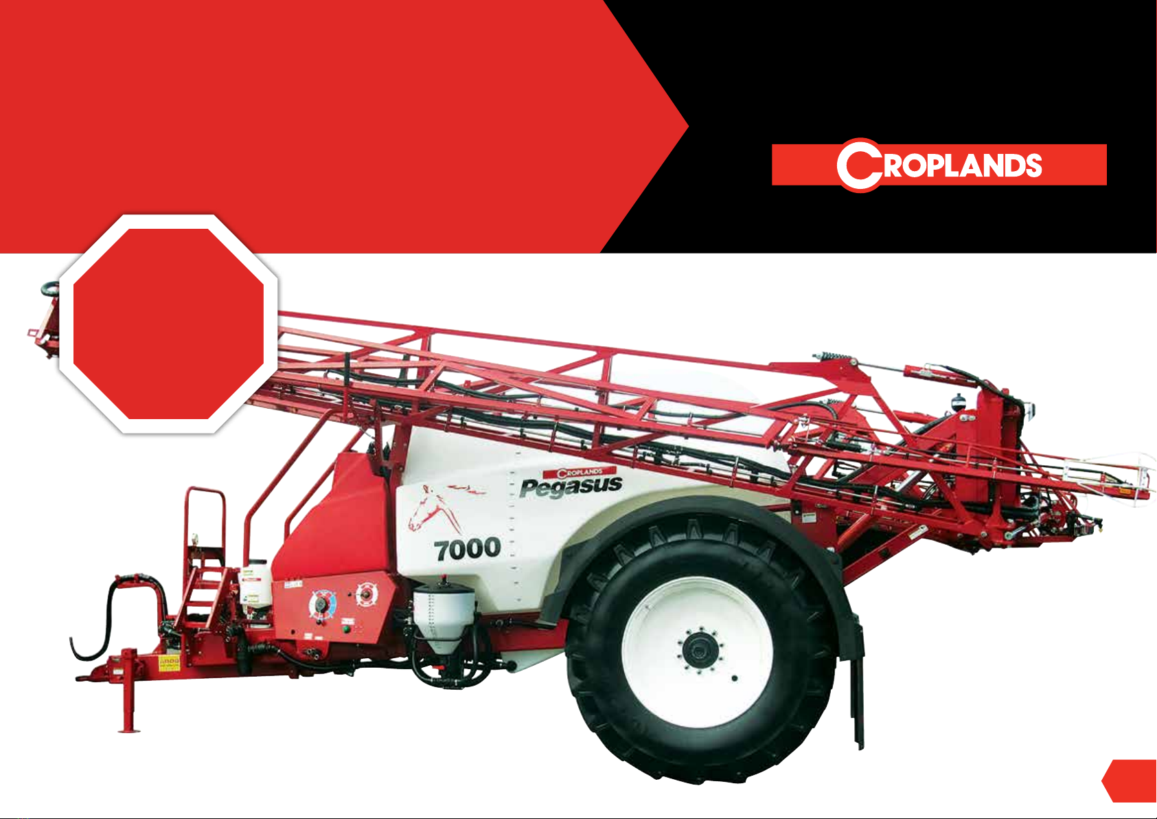
This manual provides assembly, setting up, operating and
maintenance instructions for the Croplands Pegasus 7000
Standard, broadacre sprayer.
Some features explained in this manual may not be installed
on your sprayer.
Please pass on this manual with the sprayer at the time of resale
for usage by the new owner.
This manual, BT-OMPEG7STD-A - Rev 1, was published in
May 2020.
Check online as there maybe more recent revisions of this
manual.
TERMINOLOGY
These terms/symbols used throughout
this manual:
NOTE to convey useful operating
information.
CAUTION to highlight potential injury
or machinery damage.
WARNING
to stress potential dangers
and the importance of
personal safety.
DANGER probability of death or serious
injury if accident occurs.
BEFORE OPERATING YOUR SPRAYER
1. Before attempting to use your sprayer, make sure
you read all Operator Manuals for this sprayer
including but not limited to:
• This Operator’s Manual
• Quick Start Guide, Part No. BT-PEG7STD-QS1
• Croplands Safety Part No. GP-SAFE-A
• Croplands BA7000 Operators Manual (if applicable)
• Pentair Hypro Series 9316, or equivalent,
Instruction Manual
• Arag Visio
Read and understand this Operators’ Manual before
operating the sprayer.
and properly understand:
• All Safety Issues.
• Assembly & Installation instructions.
• Calibration of the sprayer.
• Sprayer Operation.
• Sprayer Maintenance.
2. Read and follow instructions on chemical
manufacturers’ labels.
3. Always wear applicable protective clothing.
DANGER
!
Probability of a death or serious
injury if accident occurs
WARNING
!
To stress potential dangers and the
importance of personal safety.
CAUTION
!
To highlight potential injury or
machinery damage.
NOTE
To convey useful operating information.

5
SECTION 1
IMPORTANT INFORMATION
WARRANTY &
PREDELIVERY BOOKLET
Refer to your Croplands Warranty
and Pre-Delivery Boolet supplied with
your sprayer.
Always make contact with your
Croplands Dealer first and foremost
for warranty matters.
NOTE
For full conditions of warranty and warranty
policy, please see the Warranty & Pre-Delivery
booklet provided with this sprayer.
Part No. GP-WARB-A
www.croplands.com.au
BROADACRE

BT-OMPEG7STD-A
6
SECTION 2
SAFETY
SAFETY FIRST
Please read and understand all supplied manuals,
guides and safety decals before operating this
sprayer. This includes the Croplands Operators Safety
Manual – as pictured here.
This manual is available on the Croplands Web site,
or for printed versions contact Croplands customer
support and ask for part number GP-SAFE-A (or later
version if available).
OPERATORS
SAFETY
MANUAL www.croplands.com.au
STOP
BEFORE COMMENCING
operation, ENSURE you read
& understand this manual, its
contents, and any additional
information supplied.
GP-SAFE-A
STOP
BEFORE COMMENCING
operation, ENSURE you read
& understand this manual, its
contents, and any additional
information supplied.

7
SECTION 2
SAFETY
OUR WARNING LABELS
Decals - Please order replacements if required. Make sure all boom safety decals are clear and in place. Replace them if damaged.
Part No: XD -175
Part No: XD -176
Part No: XD-190
Part No: XD-182
Part No: XD -124V
Part No: XD-181
Part No: XD-125
Part No: XD -177
Part No: XD-178
Part No: XD -103
Part No: XD -125V
Part No: XD -126V
Part No: XD -123
WARNING
!
1. Read your operators manual thoroughly before
operating the srayer.
2. Inspect hoses, connections and nozzles daily.
3. Clean filters regularly.
4. Always follow correct maintenance schedules
outlined in operator’s manuals.
5. Always read chemical manufacturers labels before use.
6. Always observe all warnings on chemical products.
7. Regularly check all nuts and bolts are tight.
8. Always wear rubber gloves and wash sprayer down
before doing any repair or maintenance work.
9. Do not ride on sprayer when moving.
10.Keep clear of moving parts when sprayer is operating.
11. Always keep guards in place when sprayer is operating.
12. Be sure tank lid is closed before operating basket
mixing facility.
13. Stand well clear of sprayer when operating.
14. Do not disconnect hoses, nozzles or filters while
sprayer is operating.
FAILURE TO FOLLOW THE ABOVE INSTRUCTIONS
MAY RESULT IN SERIOUS INJURY OR DEATH.
Croplands Equipment Pty Ltd XD-123MS
SAFETY INSTRUCTIONS

BT-OMPEG7STD-A
8
SECTION 3
PRODUCT SHIPPING, IDENTIFICATION & SPECIFICATION
SHIPPING INFORMATION
The following shipping information is provided but
variations can occur without prior notification.
Approx Weight
Model Approx Dry Weight
7000 litre ? kg (36m boom)
Maximum Towing Speed
Do not exceed 25 kph when towing on roads.
Maximum speed is limited by boom wheel oscillation,
which will vary depending on road conditions.
Dimensions & Weight (Approx)
Width (3.0m axle): 3.62m
Drawbar Weight:
Boom open (tanks empty) 0.50 kg
Boom folded (tanks empty) 800 kg
Boom open (tanks full) 5610 kg
Boom closed (tanks full) 6460 kg
PRODUCT IDENTIFICATION
Always use the serial number of the Optical Spot Sprayer
when requesting service information or when ordering parts.
Early or later models (identification made by serial
number) may use different parts, or it may be necessary to
use a different procedure for specific service operations.
Sprayer’s Serial Number Identification plate.
CONTROLLER SERIAL NUMBER
The Controller Serial Number is located on the back of the
console (D).
Controller Serial Number.
7000 DESCRIPTION & SPECIFICATIONS
7000 litre Main Tank
7000 litre polyethylene lank, fitted with hinged lid and
controlled overflow plumbing, filling strainer, top fill and
fully draining sump. Comes standard with dual agitators,
tank rinsing facility and drain outlet. UV and chemical
resistant.Special tank shape helps control foaming issues.
Main tank has calibration marks.
1500 litre Tank
1500 litre polyethylene tank, fitted with dual lids and
controlled overflow plumbing. Top fill and fully draining
sump. Red tank for reduced algae issues. UV and chemical
resistant. Easy to see sight gauge.
Chassis
Heavy duty fabricated chassis with easy access walk over
platform designed for maximum accessibility and safety.
Pegasus 7000

9
SECTION 3
PRODUCT SHIPPING, IDENTIFICATION & SPECIFICATION
Easy access to main tank lid. Fitted standard with 710/70R
x 42 single wheels and tyres.
Standard axle is fixed track 3.0m axle with airbag suspension
and automatic ride height valve. Mudguards and mudflaps
are standard.
Heavy duty adjustable ARDS draw bar with air bag
suspension and automatic ride height valve. Options include
Drum rack on right hand side below the flush tank; Hydraulic
jack version; LED Lighting for fill station. Trailer light kit.
Mudguards (pair) and mudflaps (pair).
Boom
33 and 36 metre compact XL, fully hydraulic fold boom -
stronger and designed for smoother, more accurate spraying
and long life. Hydraulic accumulator boom suspension
system protects the boom and improves the boom ride.
Independent outer wing fold fitted standard. Parallelogram
2000mm hydraulic lift, adjustable boom breakaways with
self-returning boom ends. Boom hydraulically side folds and
locks for transport. Self-levelling. Protected nozzle bodies
and skids standard. Wing tip protection standard on all
booms. Chemical and corrosion resistant finish.
Manual boom flushing taps, in-line boom filters and stainless
steel boom lines standard. Agrotop AirMix® low pressure
air-induction nozzles, 110° #02 fitted as standard. Standard
boom is 500mm nozzle spacing.
Optional: Hydraulic wing lift with electric/hydraulic
operation with in-cab control panel available on all booms.
25cm nozzle spacing.
Chemical Handling
60 litre Chem-e-Flush hopper with drop down leg. Separate 30
litre fresh water/hand washing tank fitted for operator safety.
Optional: Integrated suction probe transports chemical
directly into the main tank, without putting neat chemical
through the pump. 2” Arag Orton electro magnetic fill meter.
Pump
Fitted with a Hypro Forcefield hydraulically driven centrifugal
pump. This is a large capacity pumps for high speed self
filling and fast response to the demands for auto section
controls. Ideal with large tanks demanding good agitation.
Optional: Stainless steel pump. Fenceline nozzles. 3” fast fill kit.
Fill & Filtration
2” self filling pump delivers water to the control panel rotary
valve, filling main tank or flush tank. Multiple filtration points:
Basket 18 mesh (main tank only; 2 x filling 32 mesh 2 x
pressure 80 mesh; Multiple 100 mesh boom in-line filters,
fitted to the blanket line. Self filling 3” coupling and plumbing
feeds the Hypro pump that delivers the water at high pressure
to the 2” directional fill system.
Controls
Easy to use main control panel, hinged for easy access to
plumbing. Electric compressor with large air reservoir for
airbag suspension to main axle and ARDS drawbar. BA7000
automatic sprayer controller for increased spraying accuracy,
5 section standard (optional 7 or 9 sections).
Electric motorised valves with 1” servo valve and ARAG Wolf
flowmeter. Electric dump valve standard.
The ARDS drawbar airbag
BA7000 Controller Console
Visio Flowmeter

BT-OMPEG7STD-A
10
HOOKUP 11
IMPORTANT STARTUP PROCEDURE 18
AIRBAG & HITCH HEIGHT ADJUSTMENT 18
RIDE HEIGHT ADJUSTMENT 19
UNHOOK 21
BOOM SETUP ADJUSTMENT 22
MAIN CONTROLS & FUNCTIONS 26
PREOPERATION CHECK 28
SECTION 4
PRE-OPERATION

11
SECTION 4
PRE-OPERATION
HOOK UP
Connect the Sprayer to the Tractor
The Pegasus 7000 Plus Sprayer utilises an hydraulically
driven centrifugal pump.
Please read the set-up procedure and instructions for the
drive carefully.
Four steps are required to hook up the Pegasus 7000 Plus
Sprayer to your tractor.
1. Connect the Sprayer hitch to the tractor drawbar.
2. Connect hydraulic hoses to the tractor for the:
• Boom fold & operation, and
• Hydraulic pump drive, then, set the Hydaulic Pump
Drive.
3. Fit the Controllers:
• BA7000 Controller
• Boom Controller
• Visio Controller
• Other optional controller(s).
Boom Controller
BA7000 Controller
4. Connect all power leads direct to the battery.
After the completing the tractor sprayer hook-up and
connections, check & adjust the Boom.
1. Connect the Sprayer Hitch to
the Tractor
To connect the Sprayer hitch to a suitable tractor:
1. Align & connect the Sprayer hitch to the tractor
drawbar.
Insert the drawbar pin.
2. Lower the Sprayer hitch onto the tractor drawbar:
a) Rotate the jack handle until the Sprayer fully rests on
the tractor drawbar and the hitch jack base plate is
raised off the ground.
b) Release the spring loaded lock pin and rotate the
hitch jack until it locks into the transport postion.
c) Ensure the drawbar pin is locked in place.
Hydraulically driven Hypro centrifugal pump
Connect the sprayer to the tractor
Using the hitch jack, adjust the hitch tongue to the level of the tractor
drawbar

BT-OMPEG7STD-A
12
SECTION 4
PRE-OPERATION
3. Fasten the safety chain securely to both the Sprayer hitch
and the tractor for transporting the sprayer.
2. Connect Hydraulic Hoses to the Tractor
The Srayer uses:
• Hydraulic drive Centrifugal pump.
• Hydraulic folding of the Boom for operation
and parking.
Connect to the tractor the:
1. Pump drive hydraulic hoses, and
2. Boom hydraulic hoses.
Connect the Boom Hydraulic Hoses
To connect the hydraulic pressure and return lines of the Boom
to the tractor remotes:
1. Select the Boom hydraulic hoses. These hoses are
identified by the red coloured bands located near the end
of the hoses.
2. Remove the dust caps and clean the connectors with
a clean cloth.
3. Select the Pressure line which has a cable-tie next to
the connector and 2 coloured bands (red).
4. Connect the Pressure line to the pressure line of the
tractor remotes.
5. Connect the Return line to the return line of the tractor
remotes.
6. Join the male & female dust caps together, to keep the
caps free of dirt.
NOTE
Please read the following page to
ensure you know if your tractor has
open or closed centre hydraulics.
This is VERY important to ensure your
pump drive works correctly.
Connect the boom hydraulic hoses to the tractor
Hydraulic pump & over-run check valve assembly
Connect the hydraulic hoses to the tractor
Rotate the hitch jack until it locks into the transport postion
Ensure the drawbar pin is locked-in
The transport safety chain must be fitted

13
Connect the Primary Spray Pump hydraulic hoses to the tractor.
Join the male & female dust caps together.
Pressure Line hoses are identified by two coloured bands and a cable-tie.
SECTION 4
PRE-OPERATION
Connect the Pump Drive Hydraulic Hoses
To connect the hydraulic pressure and return line of the
Centrifugal Pump drives to the tractor remotes:
1. Select the pump hydraulic hoses. The pump hydraulic
hoses have yellow bands (pressure line has 2 colour
bands & a cable-tie), and is closest to the chassis rail
2. Remove the dust caps and clean the connectors with
a clean cloth.
3. Select the Pressure line which has a cable-tie next to
the connector and 2 coloured bands.
4. Connect the Pressure line to the pressure line of the
tractor remotes.
5. Connect the Return line to the return line of the tractor
remotes.
6. Join the male & female dust cap ends together, to keep
the caps free of dirt.
Hydraulic Motor Driven Centrifugal Pump -
9316C3U-C3U-M10
Recommended for use on the following hydraulic systems:
• Pressure Compensating Closed Center
• Load Sensing or Pressure Flow Compensating Closed Center
• Open Center up to 1177 l/min.
NOTE
The pump used on your sprayer may not
be the same as shown. Always refer to the
pump manual shipped with your sprayer.
Hydraulically driven Hypro centrifugal pumps - BA7000 Controller
Console. Left: Cast Iron; Right: Stainless Steel (optional).
NOTE
Ensure the marked hydraulic line
is designated as our pressure line
(see picture above).
Performance Chart of the Forcefield™ Hypro Centrifugal Pump - Model
9316C3U-C3U-M10.

BT-OMPEG7STD-A
14
SECTION 4
PRE-OPERATION
Specifications:
• Open Center up to 1177/min
• Maximum Pressure 128 psi
• Suction 3” / Discharge 2”
• Integral Needle Valve bypasses up to 1177 l/min
on Open Cente systems
• Standard Ceramic seal or Optional Silicon Carbide Seal
• Chemical Resistant Nylon or Optional Polypropylene
or XT Impeller
• Stainless Steel Shaft and Wear Ring.
3. Fit the Controller:
• BA7000 Controller
• Boom Controller
• Visio Controller
• Other optional controller(s).
Fit the BA7000 Controller
To fit the B7000 Controller:
1. Unpack the B7000 Console, looms and mounting
components.
2. Position the Console in the tractor cab so that it is:
• Easily-reached for operating
• Easily-read
3. Firmly fix the Console mount to the tractor with the
screws & nuts provided.
4. Fit the loom connectors to the Console:
a) Align the loom connector to the Console’s base
connector & push them together.
b) Rotate the ring-lock clockwise to lock the
connectors in place.
c) Align the loom connector to the Console’s side
connector & push them together.
d) Rotate the lock clockwise to lock the connectors in place.
5. Connect the power loom connectors of the Console.
6. Run the other end of the Console loom to the rear of
the tractor.
Position the Console in the tractor cab & fix the mount
Fit the loom connectors to the Console.
Run the other end of the Console loom to the rear of the tractor.
Connect the Console power loom connectors

15
SECTION 4
PRE-OPERATION
7. At the rear of the tractor, connect the Console & Sprayer
looms:
a) Remove the dust caps from the Console & Sprayer looms.
b) Align the female connector with the male connector &
push them together.
c) Rotate the clips and lock the connectors in place.
d) Lock the male & female dust caps together, to
keep them clean.
8. Firmly fix the loom connector base to the the rear
of the tractor
9. Run the Console Power loom to the tractor battery.
Fit the Boom Controller
To fit the Boom Controller:
1. Unpack the Boom Console, looms and mounting
components.
2. Position the Console in the tractor cab so that it is
easily-reached for operating
3. Firmly fix the Console mount to the tractor with the
screws & nuts provided.
4. Fit the loom connectors to the Console:
a) Align the Power loom connector to the Console
Power connector & push them together until the
clip locks in place.
b) Align the loom connector to the Console’s loom
connector, then, rotate and lock them together.
5. Run the other end of the Console loom to the rear of
the tractor.
6. At the rear of the tractor, connect the Console &
Sprayer looms:
a) Remove the dust caps from the Console &
Sprayer looms.
b) Align the female connector with the male connector
& push them together.
7. Run the Console Power loom to the tractor battery.
Fit the Visio Controller
Boom Controller
Unpack the Visio Console, looms & mountings.
Align the female & male connectors & push them together
Rotate the clips & lock the connectors in place.
Lock the male & female dust caps together, to keep them clean

BT-OMPEG7STD-A
16
Position the Console in the tractor cab & fix the mount
SECTION 4
PRE-OPERATION
To fit the Visio Controller:
1. Unpack the Visio Console, looms and mounting
components.
2. Position the Console in the tractor cab so that it is:
• Easily-reached for operating
• Easily-read
3. Firmly fix the Console mount to the tractor with the screws
& nuts provided.
4. Fit the loom connectors to the Console:
a) Align the Power loom connector to the Console
Power connector & push them together until the
clip locks in place.
CAUTION: A RED cable-tie is fitted to the Power
connector. Ensure this connector is fitted to the
Power connector. Damage will occur to the controller
if fitted incorrectly.
b) Align the loom connector to the Console’s loom
connector & push them together until the clip locks
in place.
5. Run the other end of the Console loom to the rear of
the tractor.
6. At the rear of the tractor, connect the Console &
Sprayer looms:
a) Remove the dust caps from the Console &
Sprayer looms.
b) Align the female connector with the male connector
& push them together.
7. Run the Console Power loom to the tractor battery.
Fit Other Optional Controllers

17
SECTION 4
PRE-OPERATION
Other option controller may include:
• Electric fence-line controller.
To fit the Electric Fence Line Controller:
1. Unpack the Electric Fence Line Controller (including
Controller loom & Power loom) and mounting bracket.
2. Locate the Controller in the tractor cab so that it is easily-
reached for operating.
3. Firmly fix the mounting bracket of the Controller to the
tractor, then, slide the Controller onto the bracket until it
locks into place.
4. Connect the Sprayer Fenceline Controller loom to the
Tractor Controller loom:
a) Remove the dust caps from the ends of the looms.
b) Align the female loom connector to the male
Controller connector, then, push them together until
they click in place.
c) Lock the male & female dust caps together, to keep
them clean.
5. Run the battery connectors of the Fencline Power Loom
to the tractor battery.
4. Connect All Power Leads to the Tractor Battery
Connect all power leads directly to the battery,
namely the:
• BA700 Controller
•Boom Controller
• Visio Controller
• Other optional controller(s).
Optional Electric Fence Line Controller
Connect the Fenceline Controller loom.
Optional Fenceline Controller power loom.
Bravo, Visio & Trailing Boom Controller power looms
NOTE
For operating instructions of this model of
spray controller you have been supplied, refer
to the controller manual supplied seperately.
CAUTION
!
Make absolutely certain that:
• Red leads are connected to the positive
terminal, and
• Black leads are connected to the
negative terminal.
Damage can occur to the systems if power
leads are reversed or incorrectly fitted.
NOTE
ALWAYS “FIRST” Switch-On a Spray
Controller - Before engaging hydraulic pump
drives. The Air system should ALWAYS be
Turned ON - BEFORE starting pump drives.
It is also recommmended that airbags are
fully inflated before travel or filling the
Sprayer with water.
WARNING
!
DO NOT have pesticides in the
spraytank when checking the sprayer.

BT-OMPEG7STD-A
18
SECTION 4
PRE-OPERATION
IMPORTANT STARTUP PROCEDURE
The Pegasus 7000 Plus Sprayer uses compressed air in the:
• Main Axle airbag suspension
• ARDS Drawbar airbag, and
•Boom nozzle switching system.
Regularly drain the water from the air tank and regulators.
To charge the Air System, TURN-ON the Main Controller.
This engages the compressor to charge the air system.
Always charge/inflate the Air System BEFORE engaging
hydraulic drives which drive the centrifugal pumps of
the sprayer.
It is also recommmended that airbags be fully inflated
before travel or filling the Sprayer with water.
AIRBAG & HITCH HEIGHT ADJUSTMENT
For the first time setup, consult the Pegasus Quick Start Guide.
Setup & adjustment is best done with the Pegasus Sprayer
hitched to the tractor and on level ground and the booms
opened to their spraying position.
For optimum results the Pegasus boom height should be set
according to the nozzles fitted.
The Pegasus Sprayer Airbag suspension and drawbar system
are factory set according to the instructions given here.
If required the following settings can be checked and
adjusted on theSprayer:
• Drawbar hitch height
• Main axle airbag inflation level
• ARDS Drawbar airbag inflation level.
To make adjustments, follow the instructions that follow.
The chassis angle of the Sprayer is designed to operate at a
nominal 5 degrees forward -sloping-down.
Ideally the chassis remains at this angle after the boom height
adjustment is completed. However some variation (+/- 1 degree)
in order to achieve correct sensor height is acceptable.
Follow the procedures outlined (1 to 5) to correctly adjust the
boom height.
The recommended procecedure for the Sprayer boom height
adjustment is:
1. First, connect the sprayer to the tractor (refer to instructions
on page 2.13).
2. Set the ARDS Drawbar airbag adjustment to “standard”
height
Pegasus 7000 Quick Start Guide
Main Axle airbag
The ARDS drawbar airbag at the rear of the hitch
Nominal 5 degrees forward-sloping-down chassis
The front drawbar hitch tongue is height adjustable

19
SECTION 4
PRE-OPERATION
3. Set the Main Axle airbag adjustment to “standard” height.
4. Adjust the Sprayer hitch tongue to match the height of
the tractor drawbar and maintain the 5 degree forward
sloping angle of the Sprayer’s chassis.
RIDE HEIGHT ADJUSTMENT
1. Connect the Sprayer to the Tractor
First, connect the sprayer to the tractor (refer to instructions
on page 2.14).
The starting position is with the hitch tongue located in the
top holes (opposite to that pictured above).
The hitch tongue is height adjustable and can also be
turned 180 degrees.
2. Set the ARDS Drawbar Airbag “Standard”
Height
The ARDS drawbar airbag level is set using the air valve
adjustment rod (on the left hand side underside of the
chassis adjacent to the drawbar).
The inflation of the ARDS drawbar airbag is supplied via
the pressure regulator attached to the air tank. It is factory
set at 40 psi (via pressure regulator).
To set the drawbar airbag level, loosen the hose clamp,
slide the control rod up or down, then retighten the clamp:
• Start with 35mm gap between drawbar and rubber
stop plate above the hitch.
• Adjustment range is 20 ~ 50mm.
The Sprayer’s chassis should be maintained as near as
possible to the 5 degree nominal angle.
NOTE
Ensure tyres of the sprayer and boom are
correctly inflated:
• Sprayer standard tyre pressure is 24 psi
(Optional fitted tyres may be different)
Tyre inflation and soil conditions can also
affect ride heights.
Regularly open the valve to drain water from the air tank & regulators
Connect the sprayer to the tractor
The ARDS drawbar inflatable airbag mechanism
Adjust the ARDS drawbar airbag pressure to 40 psi using the pressure
adjustment valve.
Start with 35mm gap between drawbar and the rubber stop plate above it.

BT-OMPEG7STD-A
20
SECTION 4
PRE-OPERATION
3. Set the Main Axle Airbag to “Standard” Height
The main axle airbag ride height is set using the air valve
rod (on the left hand side, underside of the chassis adjacent
to the axle).
To set main axle airbag ride height, loosen the hose
clamp, slide the control rod up or down, then retighten
the clamp:
• Start with airbag setting of 310mm
• Adjustment range is 270 ~ 350mm.
4. Adjust Suspension & Drawbar Height Using
the Main Axle Airbag Adjustment
To adjust the Sprayer’s air suspension:
1. Start the air compressor and charge the air tank.
The air compressor starts automatically when the
BA7000 Controller is switched on (see page ?).
The air tank is factory set at 100 psi - this is the ideal
pressure for the main axle airbags.
This pressure is shown on the front gauge panel.
2. Check the air tank pressure is charged to the
recommended100psi.
3. If in the unlikely event it is necessary, to adjust the air
pressure setting of the main axle airbags:
• Remove the electrical fitting from the air valve
To set the drawbar airbag level, loosen the hose clamp, slide the control
rod up or down, then retighten the clamp.
To set axle ride height, loosen the hose clamp, slide the control rod up or
down, then, retighten the clamp
The front drawbar hitch tongue is also height adjustable
Check the air tank pressure is charged to100psi
Push the Power Switch On to start the air compressor
Remove the electrical fitting from the air valve
Table of contents
Other Croplands Farm Equipment manuals

Croplands
Croplands WEED-IT Quadro User manual

Croplands
Croplands PEGASUS 8000 User manual

Croplands
Croplands US20F/252/HR30 User manual

Croplands
Croplands CROPAIR 300 User manual

Croplands
Croplands PEGASUS 8000 Programming manual

Croplands
Croplands QUANTUM FUSION User manual

Croplands
Croplands US200C/25/100R3 User manual

Croplands
Croplands Quantum Mist QM-500 User manual

Croplands
Croplands WEED-IT Quadro User manual

Croplands
Croplands AgriPak LA300 User manual