OSBZX225-EN
6/8
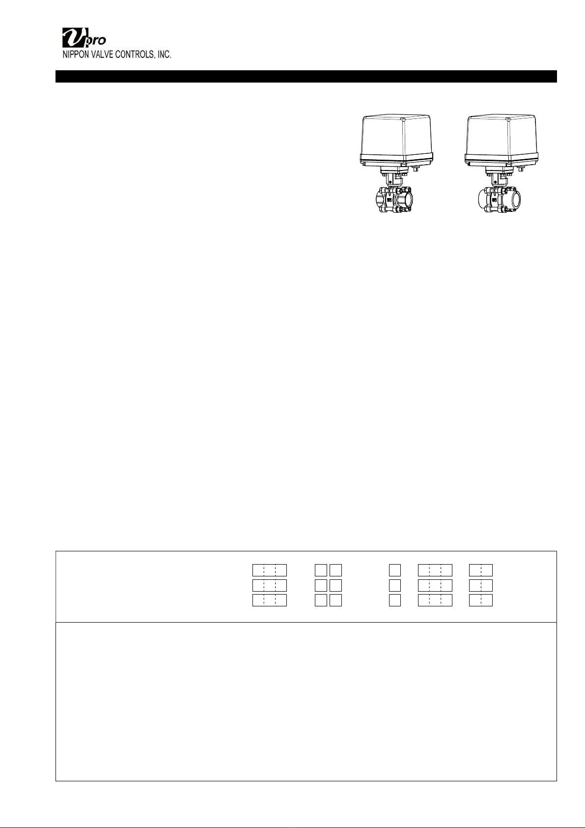
INSTALLATION, OPERATION & MAINTENANCE INSTRUCTIONS
HANDLING & STORAGE
HANDLING
Do not drop or throw the product as it may break.
STORAGE
Store away from dust, moisture and direct sunlight.
If possible, store in the original package.
CHECKING
• Check the product code, power supply, and voltage
before installation.
• Make sure that the bolts are not loose.
INSTALLATION
PRECAUTIONS
• Flush the pipeline carefully before installing the
valve. Foreign particles, such as sand or pieces of
welding electrode, will damage the disk and seats.
• When piping the valve disk should be closed before
mounting.
• Avoid oil or grease when using EPDM seat.
PIPING
• Using a pipe with too long a thread will damage the
valve.
• If sealing tape or sealant gets inside the valve, the
valve seat leaks or malfunctions.
• When connecting a pipe or fitting to a valve, use a
tool on the octagonal or hexagonal part of the
insertion side and screw it.
• Refer to the recommended tightening torque table
and do not apply excessive torque.
Valve size [mm] Torque [Nm]
015 25 to 35
020 40 to 50
025 50 to 60
032 60 to 80
040 75 to 85
050 90 to 110
Socket End
Should use adhesive suitable for valve materials.
ENVIRONMENT
• Do not install in place where corrosive gas is present
or where vibration is heavy (0.5 G or more).
• When radiant heat causes the surface temperature
of the control unit to exceed 55 °C, provide an
appropriate shielding plate.
• If there is a possibility that the fluid and drive part
freeze, please take measures to prevent freezing.
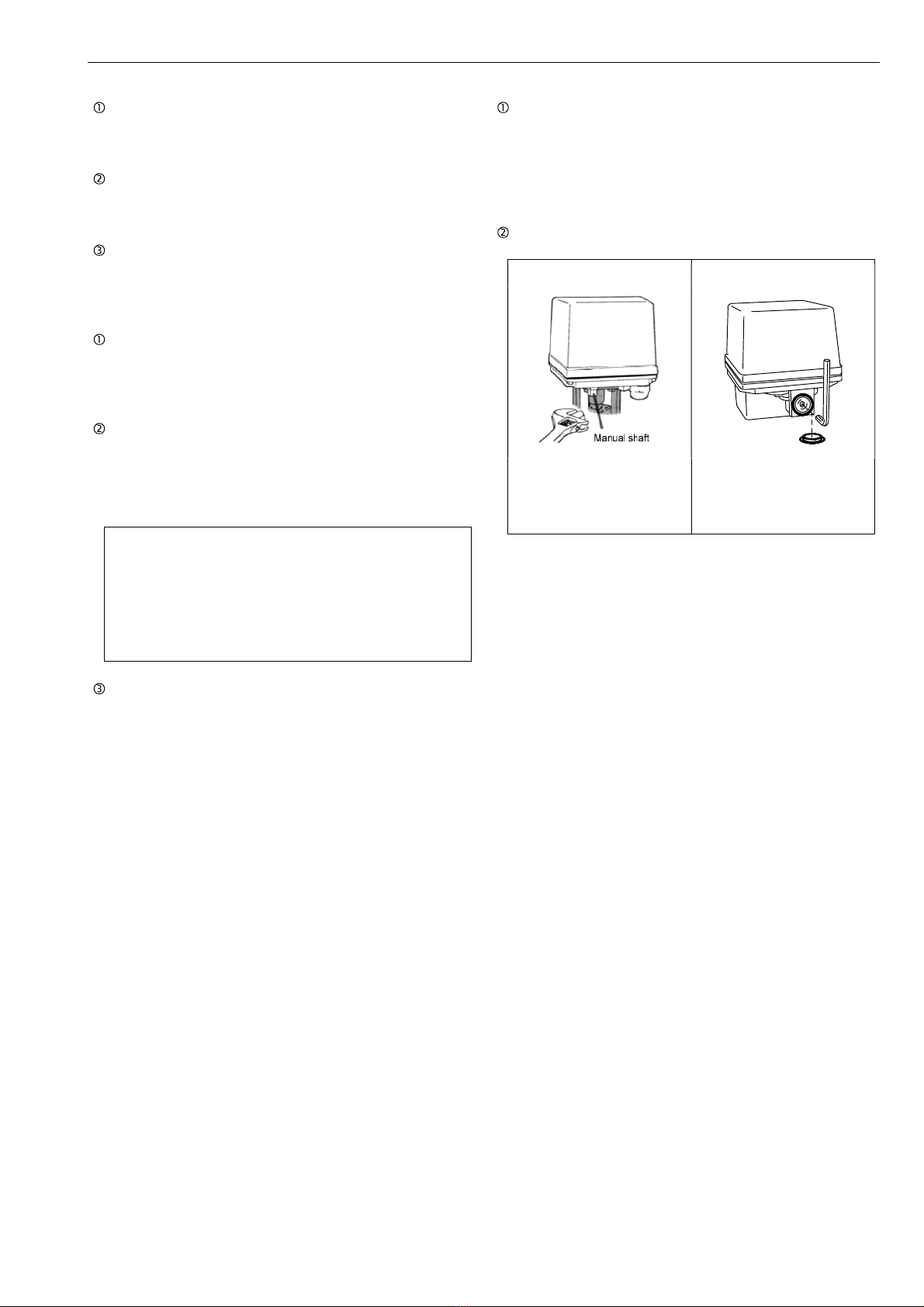
POSITIONING
Should be positioned through 90° upward from
horizontal. Provide space around the product to
allow manual operation, inspection and replacement
work.
Maintenance space for upper part of actuator.
AE (120 / 300 / 600) More than 105 mm
AE (02K / 06K) More than 120 mm
OTHER NOTES
Until the wiring is completed there must be no
condensation or flooding in the interior of the
actuator, after piping. Protective caps on the cable
gland are not waterproof.
WIRING
PRECAUTIONS
• Remove the actuator cover before wiring.
• Two G1/2 electrical connections are provided with a
cable gland and plug. Usable cable size is 6 to 12
mm.
• When using a flexible tube, dew condensation may
occur inside the actuator due to respiration from the
inside of the tube and malfunction may result. Seal
the flexible tube connector part with a sealant.
• Sealants that affect the electrical contacts should not
be used inside the electric actuator.
• If long distance wiring or low voltage operation,
check that terminal voltage is in the proper range.
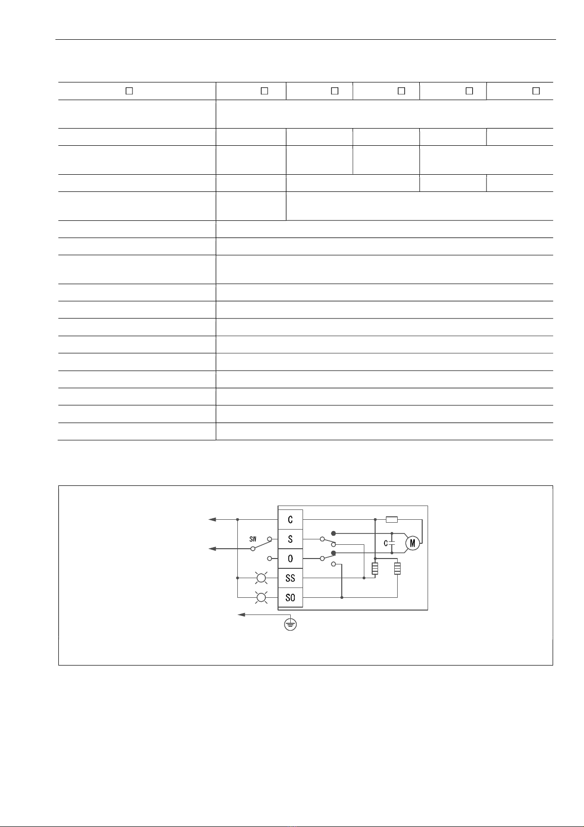
CONNECTION
• Do not wiring outdoors on a rainy day.
• Check the power supply and voltage.
Connect the signal as shown in the wiring diagram.
Do not connect unnecessarily terminal.
• Actuator should be electrically grounded.
Use the terminal marked ( ) inside the actuator.
PREVENT DEW CONDENSATION
• When installing the cover after wiring, perform the
bolt by the temporary tightening procedure and the
permanent tightening procedure to tightly and
securely tighten the rubber packing so that water
does not enter from the outside.
• Tighten the cable gland nut so that there is no
leakage from the wire entrance.