Valcom V-9964 User manual

Issue 3
1 947059
V-9964
Digital Feedback Eliminator/Message Stacker
General Design
The V-9964 is designed to eliminate acoustic
feedback and act as a message stacker. When
a page is made, the message is digitized and
saved. Upon completion of the live page, the
message is released for broadcast over the
speakers. While a message is being broadcast,
a second message may be recorded.
Additionally, up to four V-9964 units may be
chained together to allow up to eight messages
to be simultaneously processed.
Specifications
Features
•Automatic Gain Control (AGC)
•Adjustable VOX sensitivity
•Compatible with Valcom Multi-Zone Control
Units and Station Adaptors
•Two input channels: Switch selectable
primary and priority, or two channels with
equal priority; both inputs are switch
selectable for Loop Start or VOX operation
•Two audio outputs:
600 Ohms with loop supervision to a page
control unit or 8 Ohms line level output to
amplified speakers
•Background music input
•Total of three normally open relay contacts
for PLAY, RECORD and BUSY modes (one
contact each)
•LED status indicators for POWER,
RECORD, PLAY and BUSY
•Dip switch option programming
•Message abort feature
Access
•Vacant Loop Start Trunk Port
or C. O. Line Port
•Page Port
•Line Level Audio Feed
•An adaptor is required for C. O. Line or
Station access (see V-9970 or V-9940)
Dimensions/Weight
•11.76" H x 7.10" W x 1.72" D
(29.87cm H x 18.03cm W x .37cmD)
•2.6 lbs. ( 1.18Kg )
Nominal Specifications
Power requirement: 24VDC 200mA filtered
Input impedance: 600 Ohms
Input level: -10dBm
Loop Output impedance: 600 Ohms
Line Output impedance: 8 Ohms
Output level: -10dBm
VOX sensitivity: -20dBm to -35dBm
Message release time: 3 seconds after
Last sensed audio
Maximum recorded page time: 60
seconds
(30 seconds per page in call stacker Mode)
Frequency response:
Page 80Hz to 7kHz
Background Music 50Hz to 17kHz
Environment
Temperature: 0 to +40°C +32 to +104°F
Humidity: 0 to 80% non-precipitating

2
FCC Information
This equipment has been tested and found to
comply with the limits for a Class B digital
device, pursuant to Part 15 of the FCC Rules.
These limits are designed to provide
reasonable protection against harmful
interference when the equipment is operated
in a commercial environment. This
equipment generates, uses and can radiate
radio frequency energy and if not installed
and used in accordance with the instruction
manual, may cause harmful interference to
radio communications. Operation of this
equipment in a residential area may cause
harmful interference in which case the user
will be required to correct the interference at
his own expense.
Installation/Connection
Cabling
Category 3 or 5 twisted pair cable is
recommended for all Valcom distributed
amplified paging installations. Screw terminals
are provided for the basic connections. RJ45
jacks are provided for chaining multiple V-9964
units together. Removing the narrow right side
panel of the V-9964 provides access to controls,
connections and option switches. To remove
the panel, loosen the two screws holding the
panel in place and lift the panel.
Mounting
The V-9964 may be wall mounted or rack
mounted in a standard 19 inch equipment rack
using the brackets included.
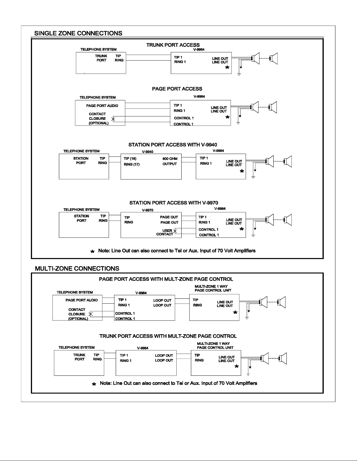
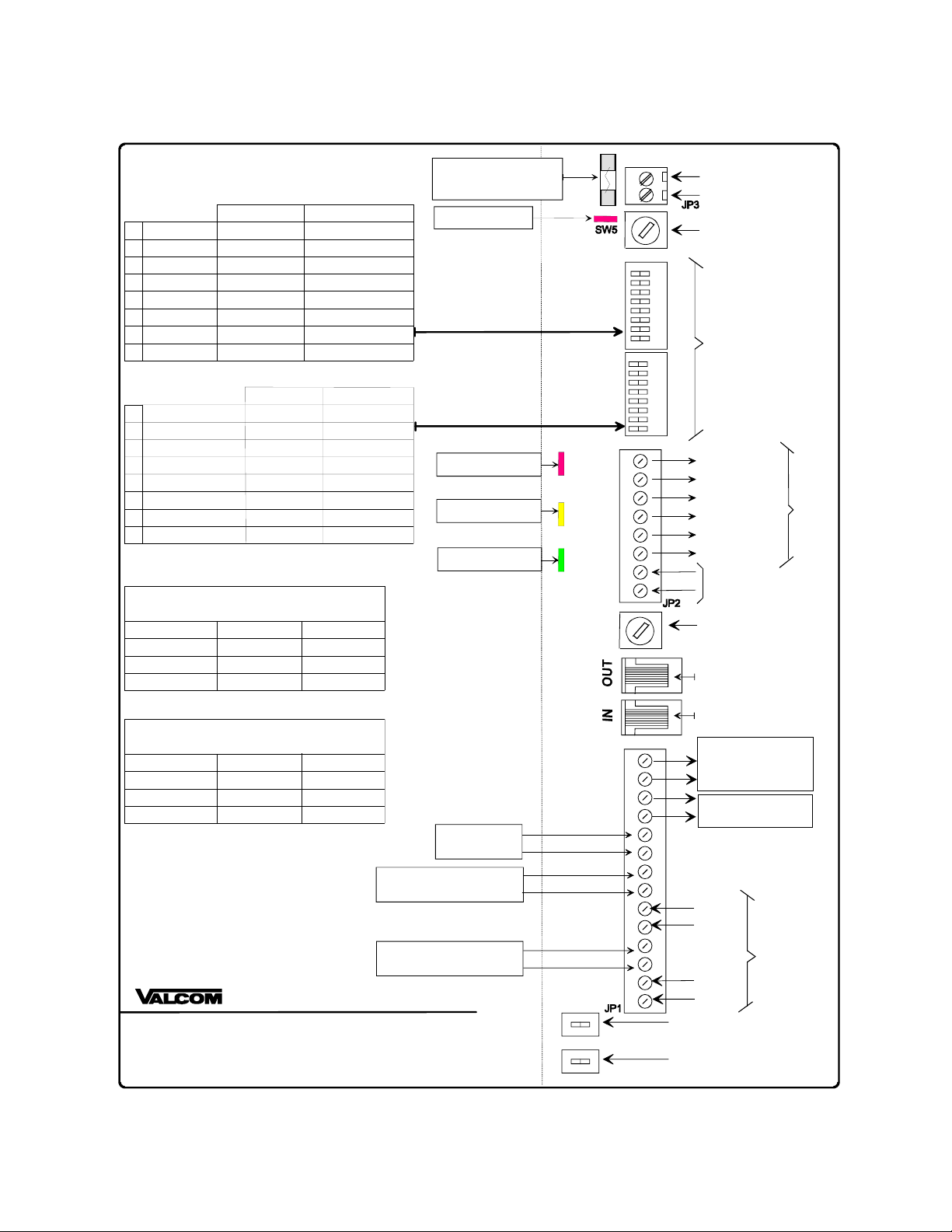
Connections
See Figure 1 for a connection diagram.
Tip 1, Ring 1
INPUT 1 is the normal Primary or Call Stacker
system input. Connects to a Loop Start Trunk
Port, 600 Ohm Page Port or some Valcom Page
Controls. Do not connect to a C. O. Line.
Control Input 1
Provides contact closure activation when using a
Page Port.
Tip 2, Ring 2
INPUT 2 is the Override page or Call Stacker
line two input. If desired, connect this to a
second Loop Start Trunk Port or Page Port.
Do not connect to a C. O. Line.
Control Input 2
Provides contact closure activation when using a
Page Port.
Background Music Input
Connection for external line level music source
(Example: V-2952, FM Tuner).
NOTE: If using multiple V-9964 units in a
chained configuration, all speakers must
connect to the output of the last unit in the
chain.
Line Out
Output connections to Valcom amplified
speakers or 70 Volt amplifier Aux input.
Loop Out
Connects to Tip and Ring input on a Valcom
multi-zone page control unit.
Expansion In
RJ45 connection from the previous V-9964 in a
chained configuration.
Expansion Out
RJ45 connection to the next V-9964 in a chained
configuration.
Abort
To abort a message during play, connect an
external relay contact across the two abort
terminals.
NOTE: To abort a message during the record
sequence, press any DTMF button on the dial
pad of the access telephone.
Relay Closure Outputs
(PLAY) PLYSW and PLYMK
Normally open relay contact that closes while a
message is being broadcast.
(RECORD) RECSW and RECMK
Normally open relay contact that closes while a
message is being recorded.
(BUSY) BSYSW and BSYMK
Normally open relay contact that closes when
the unit cannot accept any more messages.
Switches and Controls
NOTE: (OFF-Left) (ON-Right)
Refer to figure one for locations.

3
SW1: Tip 1 Ring 1
No Battery Feed (Page Port) OFF
Battery Feed supplied (Loop
Trunk Port) ON
SW2: Tip 2 Ring 2
No Battery Feed (Page Port) OFF
Battery Feed supplied (Loop
Trunk Port) ON
SW5: VOX Sensitivity
Sets audio detection threshold for input ports.
SW4-1 or SW4-2 must be in the "ON" position
for this
adjustment to be effective.
SW5 Level SW5 Level
0 -20dBm 8 -28dBm
1 -21dBm 9 -29dBm
2 -22dBm A -30dBm
3 -23dBm B -31dBm
4 -24dBm C -32dBm
5 -25dBm D -33dBm
6 -26dBm E -34dBm
7 -27dBm F * -35dBm
* Typical Setting
Program DIP Switch Settings
NOTE: (ON-Left) (OFF-Right)
SW3-1: DTMF Signaling Options
No DTMF signaling (single zone) OFF
DTMF signaling (multi-zone) ON
SW3-2, SW3-3: Number of Digits to Receive
Before Recording the Page.
1 Digit SW3-2 OFF SW3-3 OFF
2 Digits SW3-2 ON SW3-3 OFF
3 Digits SW3-2 OFF SW3-3 ON
4 Digits SW3-2 ON SW3-3 ON
SW3-4: Priority Port Options
Leave in "OFF" position when used as a Call
Stacker (SW4-4 is "ON").
Records Primary and Priority pages;
Priority page broadcast first OFF
Priority page broadcast in real-time;
Primary page in progress is recorded
and broadcast after Priority page
ON
SW3-5: Message Playback Control
Play message once OFF
Play message twice ON
SW3-6, SW3-7: Pre-page Alert Tones
No tones SW3-6 OFF SW3-7 OFF
Single tone SW3-6 ON SW3-7 OFF
Dual tone SW3-6 OFF SW3-7 ON
Quad tone SW3-6 ON SW3-7 ON
SW3-8: Inter-page Timing
1 Second between pages OFF
3 Seconds between pages ON
SW4-1: Primary or Line 1 Page Access
Loop detect OFF
Audio detect ON
SW4-2: Priority or Line 2 Page Access
Loop detect OFF
Audio detect ON
SW4-3: Pre-Record Ready Tone
Normal (3 seconds delay) with ready
to record tone OFF
No pre-record tone; allows
immediate recording activation ON
Note: This option is effective only when the
inputs are set for LOOP start (SW4-1 OFF).
SW4-4: Normal or Call Stacker Mode
2 Inputs-Primary and Priority OFF
2 Inputs will function as Call Stacker ON
Note: Only one Priority port may be used on
a Multi V-9964 system.
SW4-8 Output Control
Slave unit in a Chained system;
Multiple V-9964 OFF
Single unit or Master in a Chained
system ON

4

5
Technical Assistance
When trouble is reported, verify the unit is
turned on and there are no broken
connections leading to the unit.
Assistance in troubleshooting is available
from the factory. When calling from the job
site, you should have a Volt/Ohm Meter and
a telephone test set available for testing. Call
(540) 563-2000, press 1 for Technical
Support, or visit our Website at
http://www.valcom.com.
Valcom equipment is not field repairable.
Valcom maintains service facilities in
Roanoke, VA. Should repairs be necessary,
clearly tag the unit with your company name,
address, telephone number, contact person
and a description of the problem. Send the
unit to:
Valcom Inc.
Repair and Return Department
5614 Hollins Road
Roanoke, VA 24019-5056
VALCOM LIMITED WARRANTY
Valcom, Inc. warrants its products to be free from defects in materials and workmanship under conditions of normal use and service
for a period of one year from the date of shipment. The obligation under this warranty shall be limited to the replacement, repair or
refund of any such defective device within the warranty period, provided that:
1. inspection by Valcom, Inc. indicates the validity of the claim;
2. the defect is not the result of damage, misuse or negligence after the original shipment;
3. the product has not been altered in any way or repaired by others and that factory sealed units are unopened (a service
charge plus parts and labor will be applied to units defaced or physically damaged);
4. freight charges for the return of products to Valcom are prepaid;
5. all units ‘out of warranty’ are subject to a service charge. The service charge will cover minor repairs (major repairs will
be subject to additional charges for parts and labor).
This warranty is in lieu of and excludes all other warranties, expressed or implied, and in no event shall Valcom, Inc. be
liable for any anticipated profits, consequential damages, loss of time or other losses incurred by the buyer in connection
with the purchase, operation or use of the product.
This warranty specifically excludes damage incurred in shipment. In the event a product is received in damaged condition, the
carrier should be notified immediately. Claims for such damage should be filed with the carrier involved in accordance with the
F.O.B. point.
Headquarters: In Canada
Valcom, Inc. CMX Corporation
5614 Hollins Road 35 Van Kirk Drive #11 and 12
Roanoke, VA 24019-5056 Brampton, Ontario L7A 1A5
Phone: (540) 563-2000 Phone: (905) 456-1072
FAX: (540) 362-9800 FAX: (905) 456-2269

6
V-9964
Ground
(-)
(+)
VOX
SENSITIVITY
OPTION
SWITCHES
BSYMK
BSYSW
RECMK
RECSW
PLYMK
PLYSW
ABORT
ABORT
BACKGROUND
MUSIC LEVEL
FIGURE 1: CONNECTIONS AND CONTROLS
(ACCESSIBLE WITH SIDE PANEL REMOVED)
OFF ON
SW2
SW1
OFF ON
BATTERY
FEED 2
BATTERY
FEED 1
POWER ON LED
SYSTEM BUSY LED
RECORDING LED
PLAYING LED
600 OHM LOOP
OUTPUT TO VALCOM
PAGE CONTROL UNIT
OR OTHER DEVICES
SW4
Primary Input
Priority Input
LOOP DETECTAUDIO DETECT
LOOP DETECT
AUDIO DETECT
ON OFF
8
7
6
5
Tones PRE-RECORD TONENO TONES
CTRL 2
RING 2
TIP 2
RING 1
TIP 1
BACKGROUND
MUSIC INPUT
TIP 2 / RING 2
CONTACT CLOSURE INPUT
8 OHM OUTPUT TO
VALCOM SPEAKERS
TIP 1 / RING 1
CONTACT CLOSURE INPUT
CONTACT CLOSURE
OUTPUTS
BUSY MAKE
BUSY SWITCH
RECORD MAKE
RECORD SWITCH
PLAY MAKE
PLAY SWITCH
ABORT
CLOSURE
INPUT
8
7
6
5
4
3
2
1
8
7
6
5
4
3
2
1
4
3
2
1
OFF
PRIMARY / PRIORITY
CALL STACKER
System Mode
NOT USED NOT USED
NOT USED NOT USED
NOT USEDNOT USED
Output Control MASTER UNIT CHAINED UNIT
NOT USED
NOT USED
NOT USED
Switch Options
RJ45 for
Expansion Output
RJ45 for
Expansion Input
Fuse: 1 Amp 250V
2AG Fast Acting
POWER INPUT
-24VDC
SW3OptionsSW4Options
ON
ON
OFF
Expansion
Loop Out
Loop Out
Line Out
Line Out
System
Access
Inputs
SW3
DTMF Options NO DTMF Record
DTMF Record
ON OFF
8
7
6
5
Record Digits See Chart 1
4
3
2
1
Record & Play
Realtime Play
Input 2 Play Options
Play Twice Play Once
Inter Page Timing
Message Play
Record Digits See Chart 1
See Chart 1
See Chart 1
See Chart 2
See Chart 2
See Chart 2
See Chart 2
Alert Tones
Alert Tones
3 Seconds 1 Second
Settings to select Pre Page Alert Tones
CHART 2 (Switches SW3-6 & SW3-7)
Quad Tone
No Tone
Single Tone
Dual Tone SW3-6 OFF SW3-7 ON
SW3-6 ON SW3-7 OFF
SW3-6 OFF SW3-7 OFF
SW3-6 ON SW3-7 ON
Settings to select the num ber of DTMF Digits to Record
CHART 1 (Switches SW3-2 & SW3-3)
Four Digits
One Digit
Two Digits
Three Digits SW3-2 OFF SW3-3 ON
SW3-2 ON SW3-3 OFF
SW3-2 OFF SW3-3 OFF
SW3-2 ON SW3-3 ON
CTRL 2
BGM
BGM
CTRL 1
CTRL 1
Table of contents
Other Valcom Microphone manuals

Valcom
Valcom PagePac 6 Plus User manual

Valcom
Valcom V-450 User manual

Valcom
Valcom V-420 User manual

Valcom
Valcom V-400 User manual

Valcom
Valcom V-9970 User manual

Valcom
Valcom V-400 User manual

Valcom
Valcom V-2006A User manual

Valcom
Valcom V-9908 User manual

Valcom
Valcom V-400 User manual

Valcom
Valcom V-9908 User manual

Valcom
Valcom V-9934 User manual

Valcom
Valcom V-400 User manual

Valcom
Valcom V-400 User manual

Valcom
Valcom V-2006A User manual

Valcom
Valcom V-9924B User manual

Valcom
Valcom ONE-WAY PAGING SYSTEM User manual

Valcom
Valcom V-420 User manual

Valcom
Valcom V-5335405 User manual

Valcom
Valcom V-400 User manual

Valcom
Valcom V-400 User manual