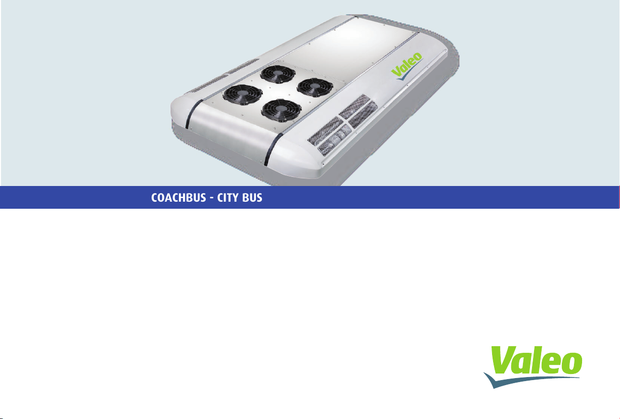
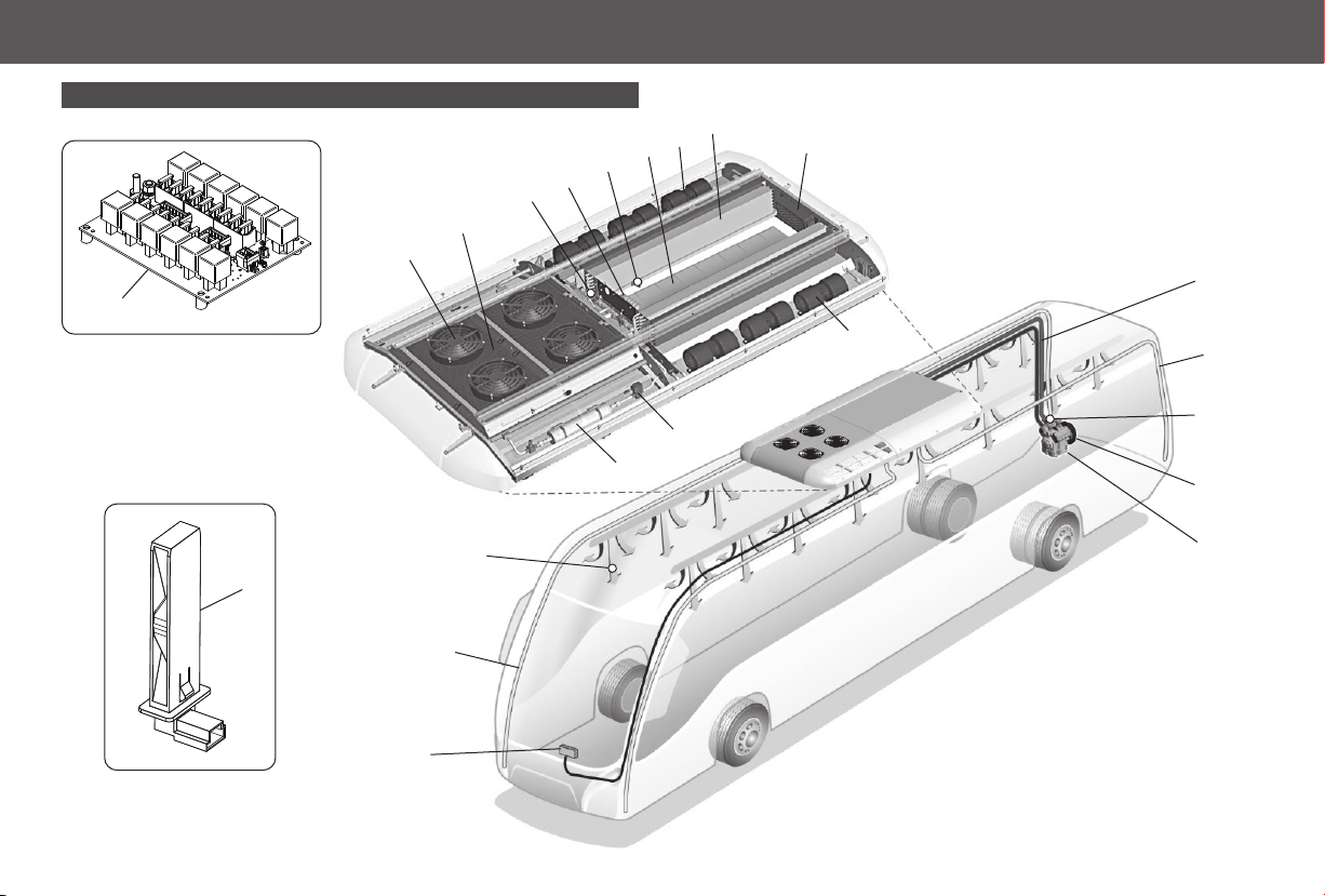
Condenser Fan
Condenser fan and the compressor will only work at
“Cool Mode”.
Refrigerant Fluid
Its main goal is dissipate the heat out, which was
absorbed by the refrigerant fluid along the
refrigeration system.
At the condenser, the overheat refrigerant fluid is
sent to outside losing its force, changing from
gaseous state to liquid state.
Condenser
Drier filter
Tiene la finalidad de retener impurezas y/o
humedad que pueda haber en el sistema
impidiendo que lleguen en la válvula de expansión.
Valve hinders the refrigerant inlet that comes from
de condenser at high pressure and its goal is adjust
the refrigerant gas flow that passed by the
evaporator looking for making the pressure steady
and temperature at the capillary tubes output.
Compressor
When it is working, the compressor sucks the refrigerant
fluid from evaporator at gaseous state and under low
pressure, compressing it, so temperature and pressure
increase, then the compressor puts it into the condenser.
MECHANIC SYSTEM
Compressor Operation
It is started up by the vehicle engine though a
pulley-and-belt system and put into action by an
electromagnetic clutch when air conditioning is
operating at “Cool Mode”.
Air refrechment
This permits the entry of the exernal in order to expel
unwanted odors and impurities from the vehicle.
Evaporator Fan
Evaporator fans are working at cool and fan modes,
fans can be set in two speeds.
Sped control can be manual or automatic.
Temperature Sensor
The interior temperature is measured by the
temperature sensor placed at the air return spot.
Pressure Switches
Pressure switches are electric devices that monitor the air
conditioning equipment operation pressure. Every time a
strong change happens from the NORMAL temperature,
they turn off the compressor immediately to avoid break.
Observation: pressures are always monitored, even if the
air conditioning is turned off.
ELECTRIC SYSTEM
Evaporators
Now at evaporators, the refrigerant fluid, at low
pressure, turns from liquid to gaseous state,
absorbing the interior heat of the vehicle in this
process.
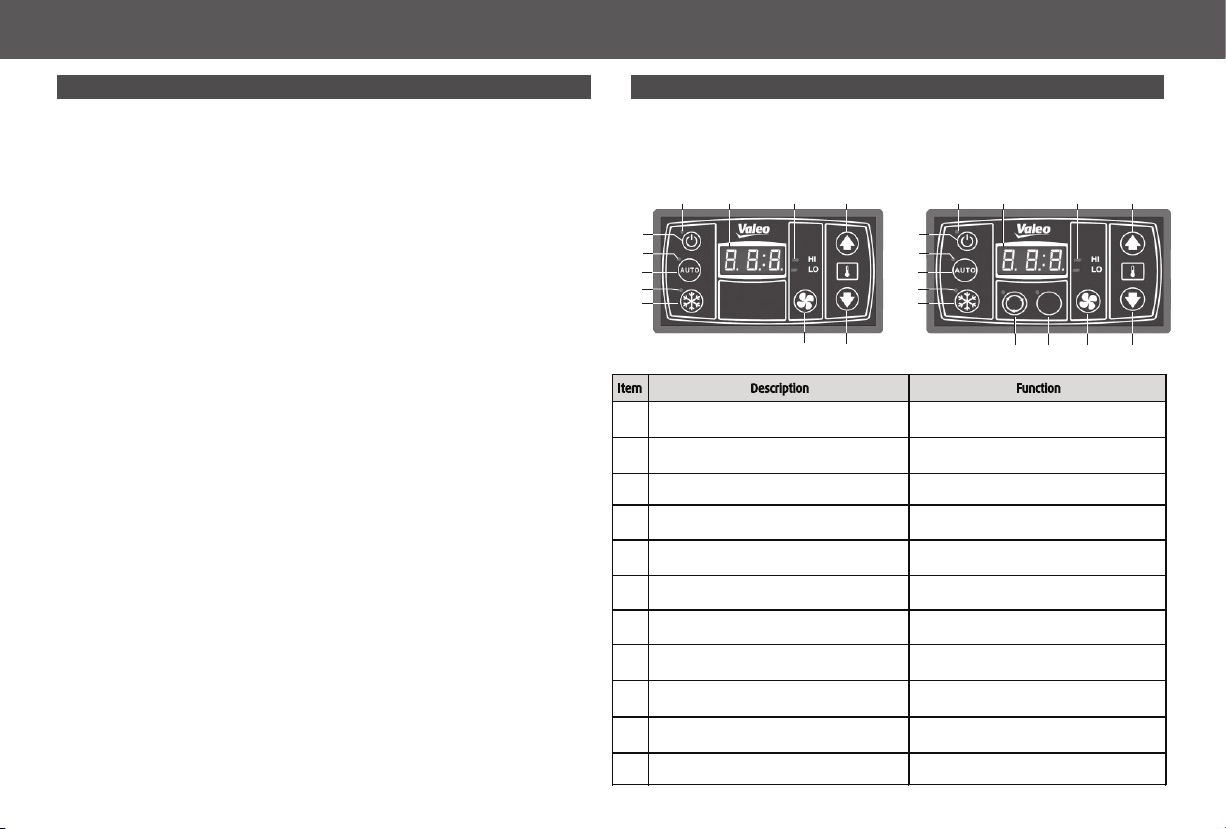
Controller
It is installed in the instrument panel, it offers to the
driver to set-point of temperature, to see by display the
interior temperature, offering full climatic control inside
de bus.
Set-point: it is the temperature the driver wishes to set
inside the vehicle for passengers.
Relay Board
Relay board has the controller controls, condenser fan
control, evaporator control and compressor control.
Air filter
Air return filter retains impurities from air avoiding
any block of dirt at evaporator capillary tubes and
coil.
Air circulation
Air being cooled by the evaporator, then it follows
to the bus interior through fans.
Drain
It is a way to get the condensed moisture from
evaporator tubes from the condensed tray to putting
out.
MECHANIC SYSTEM
ELECTRIC SYSTEM
1
2
3
4
5Expansion Thermostatic Valve
6
7
8
9
10
11
18
12
13
14
16
Solenoid Valve
15
17
Solenoid valve is applied to stop refrigerant flow through a
line. It is a closing valve controlled remotely and under
electric operation.
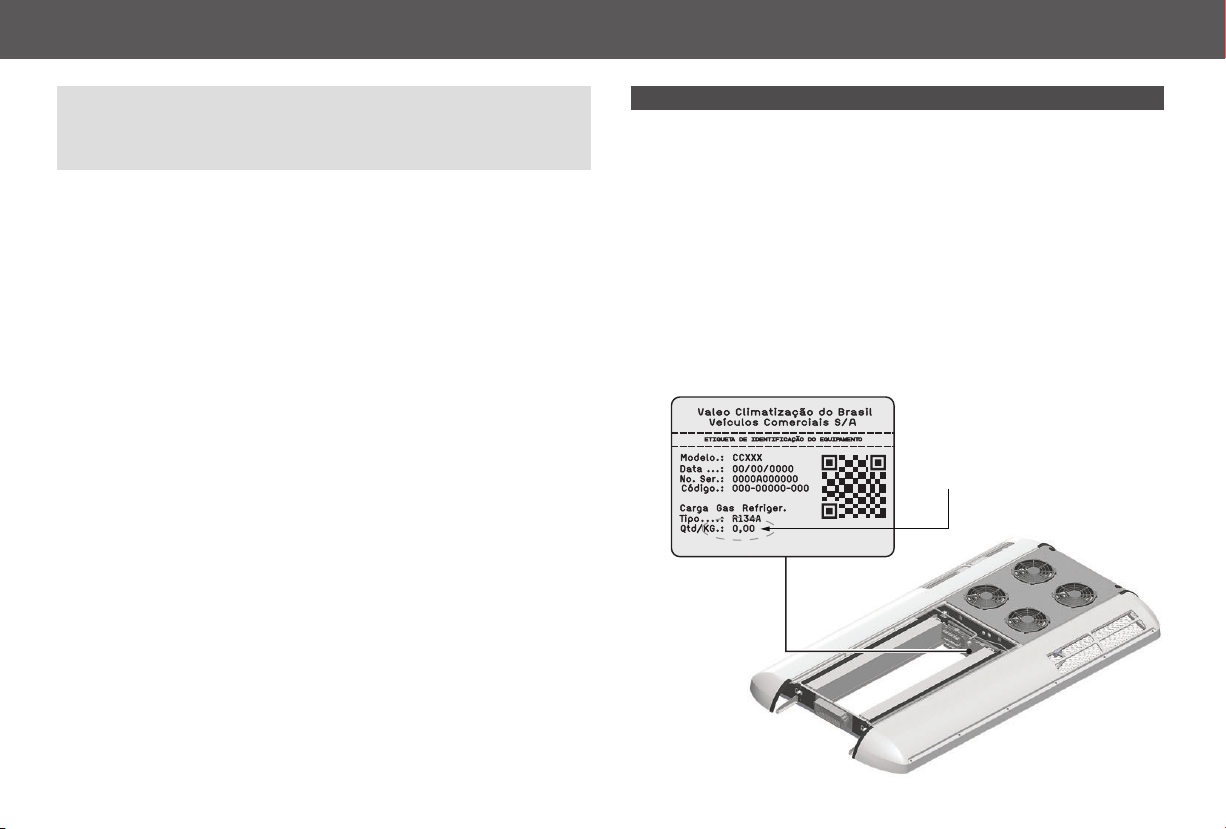
CC 305 - CC 335 - CC 355AIR CONDITIONING OPERATION
It is inside the air conditioning equipment, inside the
system. It works absorbing the heat from the interior
/ room of the vehicle, at the evaporator, and then it
goes to the condenser where the heat is thrown to
the outside. VALEO Climatização do Brasil - Veículos
Comerciais S/A, products apply refrigerant R134a,
according to the Protection Environmental Law.