Valeport miniSVS User manual

© Valeport Limited
miniSVS Operating Manual Page 1 0650808J.doc
VALEPORT LIMITED
miniSVS
Sound Velocity Sensors
Operating Manual
Document Ref: 0650808
Document Version: J
Date: July 2011
This confidential document was prepared by the staff of Valeport Limited, the Company, and
is the property of the Company, which also owns the copyright therein. All rights conferred
by the law of the copyright and by virtue of international copyright conventions are reserved
to the Company. This document must not be copied, reprinted or reproduced in any material
form, either wholly or in part, and the contents of this document, and any method or
technique available therefrom, must not be disclosed to any other person whatsoever
without the prior written consent of the Company.
Valeport Limited, Tel: +44 (0)1803 869292
St Peters Quay, Fax: +44 (0)1803 869293
Devon, TQ9 5EW, Web: www.valeport.co.uk
UK
As part of our policy of continuous development, we reserve the right to alter, without prior
notice, all specifications, designs, prices and conditions of supply for all our equipment.
Copyright 2011

© Valeport Limited
miniSVS Operating Manual Page 2 0650808J.doc
CHAPTER DESCRIPTION PAGE
1INTRODUCTION..................................................................................3
2SPECIFICATIONS ...............................................................................4
3DATA REQUESTS AND OUTPUT FORMATS ....................................7
4WIRING INFORMATION....................................................................14
APPENDIX 1: FAQ‟S..................................................................................................18

© Valeport Limited
miniSVS Operating Manual Page 3 0650808J.doc
1 INTRODUCTION
The Valeport miniSVS Sound Velocity Sensor has been designed with the objective of
providing high resolution, high accuracy sound velocity data in the most compact
package possible. The basic principle of Valeport‟s Sound Velocity technology is “time
of flight”; that is to say, the sound velocity is calculated from the time taken for a single
pulse of sound to travel a known distance.
The miniSVS therefore consists of a single circuit board controlling all sampling,
processing and communications functions, and a sensor comprising a ceramic
transducer, a signal reflector, and spacer rods to control the path length. The two are
connected by a single coaxial cable. A titanium housing may be fitted, which provides
waterproof protection to a depth in excess of 6000m.
Optionally, a strain gauge pressure sensor may be added to the miniSVS, enabling
sound velocity profiles to be obtained. This configuration is used in the SoundBar 2
Digital Bar Checker, where a 100dBar range transducer is used, but the miniSVS may
be fitted with a selection of different range transducers up to 6000dBar. The pressure
option also uses a secondary pcb.
As an alternative option, the miniSVS may be fitted with a PRT temperature sensor.
Note that as standard the miniSVS may have either the pressure
or temperature sensor fitted as an option, but not both

© Valeport Limited
miniSVS Operating Manual Page 4 0650808J.doc
2 SPECIFICATIONS
Dimensions: Dependent on type supplied. See diagram below
Connections:
Internal Co-axial connector to sensor (J3)
5 –way Harwin (power and comms) (J1)
NB: J2 & J4 are for Valeport calibration and setup purposes –not for
use by customer.
External Standard is Subconn type MCBH6F (In titanium on titanium housings,
in brass on acetal housings)
Alternatives may be supplied on request
Wiring Information is in Section 4

© Valeport Limited
miniSVS Operating Manual Page 5 0650808J.doc
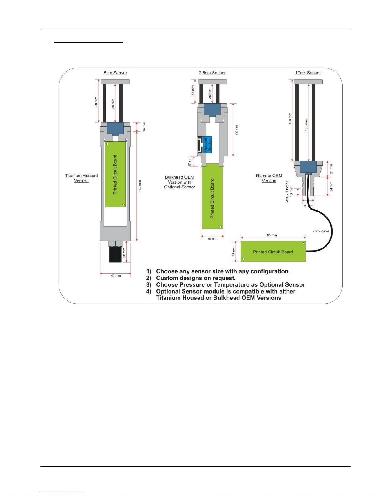
Materials:
Main housing Titanium or acetal
Main bulkhead Titanium
Space Rods Carbon Composite
Reflector Assembly Titanium
SV Transducer Ceramic transducer behind polycarbonate window.
Signal cable 3mm co-ax cable, nominal 25cm length. Push fit connector.
Pressure Transducer Stainless steel diaphragm with acetal protective cover.
Temperature sensor PRT in titanium housing with polyurethane backing.
Power:
Requires 8 –29V DC input
miniSVS draws approximately 17mA at 12vDC
miniSVS with pressure draws approximately 24mA at 12vDC
miniSVS with temperature draws approximately 20mA at 12vDC
Output:
Units are fitted with both RS232 and RS485 communications as standard. RS485 is
enabled by grounding a pin in the communications lead (refer to Section 4). Protocol
is 8 data bits, 1 stop bit, no parity, no flow control.
Baud rate is factory set to 19200. User may choose between 2400, 4800, 9600,
19200, 38400, 57600 or 115200. (Note that fast data rates may not be possible with
low baud rates).
Signal Frequency:
Single sound pulse of 2.5MHz frequency.
Update Rate:
Selected by command –Single output or continuous output at one of the following
rates: 1Hz, 2Hz, 4Hz, 8Hz ,16Hz, 32 Hz or 60Hz
.
The fastest rate possible is determined by the combination of sensors fitted:
SV only
SV + P
SV + T
Max Data Rate:
60Hz
32Hz
16Hz

© Valeport Limited
miniSVS Operating Manual Page 6 0650808J.doc
Performance:
Sensor
Resolution
Range
Overall Accuracy
25mm
0.001m/sec
1375 –1900m/s
±0.020 m/s
50mm
0.001m/sec
1375 –1900m/s
±0.019 m/s
100mm
0.001m/sec
1375 –1900m/s
±0.017 m/s
Pressure
0.01% FS
0 to 100, 500, 1000 or 6000 dBar
±0.05%FS
(over -10°C to 40°C)
Temp.
0.001°C
-5 to +35°C
(others available)
±0.01°C
Certain features of the sensor package are designed specifically to enable high quality
data to be delivered:
Carbon
Composite
Rods:
The carbon composite material used for the sensor spacer rods has
been specifically selected to provide 3 features:
a) Excellent corrosion resistance
b) Very high strength
c) Virtually zero coefficient of thermal expansion
This last point is particularly important; accurate sound velocity
measurement relies on measuring the time taken for a pulse of sound
to travel a known distance. The material selected does not
measurably expand over the operating temperatures of the
instrument, ensuring the highest possible accuracy at all times.
Size:
The longer the path length used, the higher the accuracy that can be
achieved. It has been found that a signal stability of ±2mm/sec can
be achieved with a sensor path length of 25mm (overall 50mm path
for reflected signal), falling to ±1.7mm/sec for a 100mm path (overall
200mm path for reflected signal).
Digital
Sampling
Technique:
Enables a timing resolution of 1/100th of a nanosecond, equivalent to
about 0.5mm/sec speed of sound on a 25mm path sensor, or
0.125mm/sec on a 100mm sensor. In practice, the output is restricted
to 1mm/sec resolution.
Linear sensor performance allows easy calibration.

© Valeport Limited
miniSVS Operating Manual Page 7 0650808J.doc
3 DATA REQUESTS AND OUTPUT FORMATS
The miniSVS has 3 different sampling modes, and a selection of data output formats.
Each mode is available with each output format.
3.1 SAMPLING MODES
Single [data on request]
Multiple at defined data rates [free running]
Multiple as fast as possible [free running]
3.1.1 SAMPLING COMMANDS
S<enter> Demands a single reading to be taken and data transmitted
M<enter> Unit free runs at fastest data update rate
M1<enter> Unit free runs at 1 Hz
M2<enter> Unit free runs at 2 Hz
M4<enter> Unit free runs at 4 Hz
M8<enter> Unit free runs at 8 Hz
M16<enter> Unit free runs at 16Hz
M32<enter> Unit free runs at 32Hz
M60<enter> Unit free runs at 60Hz
3.2 DATA FORMATS
Data output is dependent on the parameters fitted to the miniSVS and the output format
selected.
Pressure data format is dependent on sensor range, and may be any of the following.
Pressure value is in dBar (abs), and leading zeroes are included, so it is a fixed length
string:
PPPP.P (e.g. 1234.5 dBar)
PPP.PP (e.g. 123.45 dBar)
PP.PPP (e.g. 12.345 dBar)

© Valeport Limited
miniSVS Operating Manual Page 8 0650808J.doc
Temperature data format is fixed to a 5 digit string with 3 decimal places. Temperature
value is in °C and leading zeroes are included; it is signed only if negative. Examples:
21.456
02.769
-01.174
In the examples below, pressure data is expressed as {pressure} and the temperature
data is expressed as {temperature}
3.2.1 VALEPORT STANDARD FORMAT
#082;off Sets data format to standard Valeport mode (SV in mm/s)
SV only
<space>1234567<cr><lf>
where 1234567 is the speed of sound in mm/sec [i.e. 1234.567 m/sec]
P + SV
<space>{pressure}<space>1234567<cr><lf>
where 1234567 is the speed of sound in mm/sec [i.e. 1234.567 m/sec]
T + SV
<space>{temperature}<space>1234567<cr><lf>
where 1234567 is the speed of sound in mm/sec [i.e. 1234.567 m/sec]
P + T + SV
<space>{pressure}<space>{temperature}<space>1234567<cr><lf>
where 1234567 is the speed of sound in mm/sec [i.e. 1234.567 m/sec]
3.2.2 ALTERNATIVE FORMAT #2:
#082;2 Sets SV data format to metres per second to 2 decimal places.
SV only
<space>1234.56<cr><lf>
where 1234.56 is the speed of sound in m/s
P + SV
<space>{pressure}<space>1234.56<cr><lf>
where 1234.56 is the speed of sound in m/s

© Valeport Limited
miniSVS Operating Manual Page 9 0650808J.doc
T + SV
<space>{temperature}<space>1234.56<cr><lf>
where 1234.56 is the speed of sound in m/s
P + T + SV
<space>{pressure}<space>{temperature}<space>1234.56<cr><lf>
where 1234.56 is the speed of sound in m/s
3.2.3 ALTERNATIVE FORMAT #3:
#082;3 Sets SV data format to metres per second to 3 decimal places.
SV only
<space>1234.567<cr><lf>
where 1234.567 is the speed of sound in m/s
P + SV
<space>{pressure}<space>1234.567<cr><lf>
where 1234.567 is the speed of sound in m/s
T + SV
<space>{temperature}<space>1234.567<cr><lf>
where 1234.567 is the speed of sound in m/s
P + T + SV
<space>{pressure}<space>{temperature}<space>1234.567<cr><lf>
where 1234.567# is the speed of sound in m/s
3.2.4 CSV FORMAT (SBE CT FORMAT)
#082;csv Sets the miniSVS to output in CSV/SBE CT mimic mode
TTT.TTTT,CC.CCCCC,SSSS.SSSS,VVVVV.VVV <cr><lf>
This format mimics the SBE output format, where:-
TTT.TTTT is temperature value
CC.CCCCC is conductivity value
SSSS.SSSS is salinity value
VVVVV.VVV is sound velocity in m/s
In this format, the miniSVS will substitute zeroes for parameters it cannot
measure.

© Valeport Limited
miniSVS Operating Manual Page 10 0650808J.doc
3.2.5 SEABIRD CTD FORMAT
#082;SEABIRD Sets the miniSVS to output in Seabird CTD mimic mode
TTT.TTTT,CC.CCCCC,PPPPP.PPPP, SSSS.SSSS,VVVVV.VVV <cr><lf>
This format mimics the Seabird CTD output format, where:-
TTT.TTTT is temperature value
CC.CCCCC is conductivity value
PPPPP.PPPP is the pressure value
SSSS.SSSS is salinity value
VVVVV.VVV is sound velocity in m/s
In this format, the miniSVS will substitute zeroes for parameters it cannot
measure. Leading zeroes are replaced with spaces
NB. This output format is only available from firmware version 0650713B5
3.2.6 AML SVT FORMAT
#082;AML_SVT Sets the miniSVS to AML SVT mimic mode
<space>{temperature}<space><space>1234.567<space><space><cr><lf>
where 1234.56 is the speed of sound in m/s
In this format, the miniSVS will substitute zeroes for parameters it cannot
measure.
3.2.7 MVP FORMAT
#082;MVP Sets the miniSVS to MVP mode
<space>pppp.p<space><space>ssss.ss<space><space>tt.ttt<space><cr><lf>
Where
pppp.p denotes pressure/depth
ssss.ss denotes speed of sound
tt.ttt denotes temperature
In this format, the miniSVS will substitute zeroes for parameters it cannot
measure.

© Valeport Limited
miniSVS Operating Manual Page 11 0650808J.doc
3.3 POWER UP
There are two power up modes. The unit will either immediately begin running in
the previous sample mode, or will immediately send a „>‟ character, and wait for a
command. There needs to be a delay of at least 500ms before sending the first
command. In both cases, the data format will remain as that previously used.
#092<enter> Reads startup mode
#091;ON<enter> Readings at last rate at startup
#091;OFF<enter> No readings at startup
3.4 STOP COMMAND
The unit can be stopped at any time by sending the „#‟ character. The unit returns
a „>‟, and waits for a further command.
3.5 COMMAND ECHOES
Each command character is immediately echoed back
<Enter> is echoed back as <cr><lf>
3.6 PRESSURE FORMAT COMMANDS
#083;0 Turns pressure sensor off and unit reverts to SV only operation
mode
#083;1 Sets pressure data format to 1 decimal place
#083;2 Sets pressure data format to 2 decimal places
#083;3 Sets pressure data format to 3 decimal places
#018;0 Sets units to dBar
#018;1 Sets units to Metres
#018;2 Sets units to Feet
#019 Read Pressure Units
3.7 PRESSURE TARE COMMANDS
#011;on Turns Tare mode on (i.e. unit subtracts fixed value from pressure
data)
#011;off Turns Tare mode off (i.e. unit outputs pressure as read)

© Valeport Limited
miniSVS Operating Manual Page 12 0650808J.doc
#009; Unit takes single pressure reading to use as Tare value.
#009;0 Sets Tare value to zero (i.e. removes tare)
#009;{value} Input Tare value in units of 0.001dBar (i.e. 9000 = 9dBar)
3.8 SONARDYNE FORMAT FOR USE WITH THE COMPATT-5
#013;on Sets the unit to SONARDYNE format
#013;off Returns the unit to normal operation

© Valeport Limited
miniSVS Operating Manual Page 13 0650808J.doc
3.9 OTHER COMMANDS
#059;{baud_rate}<cr> Sets the units baud rate. Options are
e.g. #059;19200 2400,4800,9600,19200,38400,57600,115200
#031;raw Sets data output to raw format (time of flight in 100ths of
nanoseconds)
#031;cal Sets data output to calibrated format (sound velocity in
mm/sec). Unit always starts in cal mode from power on.
#001;nn Sets RS485 address (01 to 99)
#005;ON or OFF Turns Address mode ON or OFF
#006 Returns ON or OFF for address mode
#026;{xxxx} Sets data separator for Valeport mode. Default is
<space>, separator may be up to 4 characters.

© Valeport Limited
miniSVS Operating Manual Page 14 0650808J.doc
4 WIRING INFORMATION
This section contains wiring information for all sensor configurations, and includes the
standard connector types and the most commonly requested alternatives. If your
system is fitted with a connector type not listed here, then the wiring information will be
supplied as an addendum at the back of the manual. Be sure to confirm that you are
looking at the appropriate information.
Wiring colours are correct at the time the manual was printed. However, it is advised
that continuity checks are performed prior to all terminations.
OEM Systems:
Supplied with a short test lead to enable configuration and testing:
FCI 5 way
connector
Wire
Colour
Function
9 Way D Type
Connector
4mm Banana Plugs
1 (square pin)
Green
Signal / Power GND
5 (Linked to
1,6,8,9)
Black Plug, Green Wire,
connected inside 9 way D type
2
Yellow
RS232 Tx (Out of
sensor) or RS485A
2
3
Blue
RS232 Rx (Into sensor)
or RS485B
3
4
Red
+V
Red Plug, Red Wire, connected
inside 9 way D type
5
Link to Pin 1 for RS485.
N/C for RS232
Housed systems (standard Subconn connector):
Systems are supplied with a short (50cm) lead for splicing or testing
Subconn 6 pin male line
(MCIL6M)
Function
9 Way D
Type
4mm Banana Plugs
Pin
Wire Colour
Pin
Pin
Wire colour
1
Black
RS232 GND
5 (Link to
1,6,8,9)
2
White
RS232 Tx (Out of
sensor) or RS485A
2
3
Red
RS232 Rx (Into
sensor) or RS485B
3
4
Green
+V
Red Plug
Red, linked to Green
inside D type
5
Orange
Link to Pin 1 for
RS485. N/C for RS232
6 (Link to pin
1 in sensor)
Blue
Power GND
Black Plug
Black, linked to Brown
inside D type

© Valeport Limited
miniSVS Operating Manual Page 15 0650808J.doc
Alternatively systems may be supplied with a test lead connected solely through a 9-
way D-type connector.
Subconn 6 pin male line
(MCIL6M)
Function
9 Way D
Type
Pin
Wire Colour
Pin
1
Black
RS232 GND
5 (Link to
6,8,9)
2
White
RS232 Tx (Out of
sensor) or RS485A
2
3
Red
RS232 Rx (Into
sensor) or RS485B
3
4
Green
+V
7
5
Orange
Link to Pin 1 for
RS485. N/C for RS232
6 (Link to pin
1 in sensor)
Blue
Power GND
1
Housed systems (Impulse IE55-12-CCP connector, optional fit only):
Systems are supplied with a free end lead for splicing
Impulse 6 pin male bulkhead
Function
Pin
Wire Colour
1
Green
RS232 Rx (in to sensor)RS485A
2
Yellow
Power & RS232 Ground
3
Blue
9 –28vDC input
4
Red
RS232 Tx (out of sensor)RS485B
5
N/C
6
N/C
NB: RS232 and Power grounds must be linked.
Impulse 6 pin female line
Function
Pin
Wire Colour
1
Yellow
RS232 Rx (in to sensor)RS485A
2
White
Power & RS232 Ground
3
Red
9 –28vDC input
4
Brown
RS232 Tx (out of sensor)RS485B
5
Orange
Link to Pin 2 for RS485. N/C for RS232
6
Blue
N/C
Screen
N/C
NB: Do not connect screen.
View onto bulkhead
connector pins
21
34
6
5

© Valeport Limited
miniSVS Operating Manual Page 16 0650808J.doc
Housed systems (Impulse MHDG–5-BCR connector, optional fit only):
Systems are supplied with a free end lead for splicing
Housed systems (Subconn OM8F connector, optional fit only):
SVS Test Cable, 3m Valeport 8-Core Cable.
Subconn 8 pin male line
(OM8F + OMBB)
Function
9 Way D
Type
4mm Banana Plugs
Pin
Pin
Pin
Wire colour
1
+V
Red Plug
Red
2
-V
Black Plug
Black
3
4
5
6
RS232 RX (In to SVS)
3
7
RS232 TX (Out of
SVS)
2
8
RS232 GND
5 (Link to
1,6,8,9)
Impulse MHDG-5-BCR
Function
Free End
Pin
Wire Colour
Wire
1
Green
RS232 Ground
Screen
2
2
White / Black
RS232 TX (out of sensor)
3
3
White / Red
RS232 RX (in to sensor)
4
4
Red
+V
5
5
Black
-V (join to pin 1)
6
1
5
4
3
2
View onto solder buckets

© Valeport Limited
miniSVS Operating Manual Page 17 0650808J.doc
139-IPS Extension Cable, 10m Valeport 8-Core Cable.
Subconn 8 pin male line
(OM8F + OMBB + DLSB-F)
Function
Subconn 8 pin female line
(OM8M + OMBB + DLSB-M)
Pin
Pin
1
+V
1
2
-V
2
3
3
4
4
5
5
6
RS232 RX (In to SVS)
6
7
RS232 TX (Out of
SVS)
7
8
RS232 GND
8
MVP Housed systems (Subconn MCBH6M connector):
MCBH6M Bulkhead
Connector
PIN
Function
MCBH6M Titanium
2
Power GND
1
RS485A (Inverted)
4
RS485B (Non-Inverted)
3
+V
Systems are supplied with a short (50cm) lead for splicing or testing
Subconn 6 pin female line
(MCIL6F)
Function
15 Way D
Type
4mm Banana Plugs
Pin
Wire Colour
Pin
Pin
Wire colour
2
WHITE
-V
Join
BLACK &
WHITE
wires in the
hood
Black
4mm plug
BLACK
3
RED
+V
Join RED &
RED wires
in hood
Red 4mm
plug
RED
4
GREEN
RS485B (Non-
Inverted)
10,12
1
BLACK
RS485A (Inverted)
9.11
2
WHITE
RS485 GND
5

© Valeport Limited
miniSVS Operating Manual Page 18 0650808J.doc
APPENDIX 1: FAQ’S
Why is the data different from my old CTD data?
Quite simply, the Valeport SV sensor is more accurate than anything else that has
previously been available. The CTD formulae (Chen & Millero, Del Grosso etc.) all have
errors in them –they were after all based on observed data taken over 30 years ago
using the best technology available at the time. The Valeport SV sensor simply
highlights those errors. This does raise an interesting point –if it is more important to
you that your data is consistent with old data, rather than accurate in its own right, then
you are possibly better off using a CTD (we would suggest a Valeport CTD, naturally).
How is it so accurate?
Several reasons. Primarily, we use an advanced digital signal processing technique
that removes virtually all noise from the data, tells us the precise moment that the sound
pulse is both transmitted and received, and allows us to measure the time of flight with a
resolution of 1/100th of a nanosecond (10-11 seconds). Secondly, we have developed a
carbon composite material that doesn‟t expand or contract with temperature, so our
“known distance” is a constant. Technically, the material will expand and contract
minutely, but over the operating temperatures of the probe, it is an almost immeasurably
small amount, and any change is included in our overall error budget. Finally, our
calibration method removes virtually all of the error sources associated with other
techniques.
But don’t you just calibrate it against Chen & Millero?
No we don‟t – that would defeat the purpose. While the seawater formulae (Chen &
Millero, Del Grosso etc.) have inherent errors that are accepted as being at best
±0.25m/s, we use a different formula to calibrate the sensor. Del Grosso also published
a formula for speed of sound in pure water (with Mader, 1972), which is much more
accurate. In pure water, the only variable that can affect sound velocity is temperature
(assuming that you are at atmospheric pressure in a laboratory environment), rather
than both temperature and Salinity with the seawater equations. The Del Grosso &
Mader formula therefore has an error of just ±0.015m/s. By calibrating against this
rather against the error-filled seawater equations, we can achieve significantly better
performance.

© Valeport Limited
miniSVS Operating Manual Page 19 0650808J.doc
Is a pure water calibration valid?
Absolutely –the purpose of a calibration is just to compare (and adjust) the sensor
output against a known standard –it doesn‟t really matter what that standard is, as long
it is precisely defined. Our standard happens to be pure water because it is the most
accurately defined standard available.
How often does it need calibrating?
The SV sensor itself is remarkable stable. Since the entire timing system is digital, it is
not subject to the drift that analogue components often exhibit over time. The only part
of the system that can drift with time is the timing crystal itself. This is typically less than
±0.005m/s in the first year, and less than ±0.002m/s in subsequent years. We quite
confidently say that the SV sensor should remain within specification for several years.
However, the temperature and pressure sensors (if fitted) do exhibit greater drift with
time. It is our experience that in the majority of cases, performance can be maintained
by recalibrating at 2-yearly intervals. However, we are aware that many operators‟ own
QA requirements state annual recalibration, and it is true that most instruments are
returned to us on a yearly basis.
What is the response time?
Virtually instant –the sound pulse takes a matter of microseconds, and the
measurement is made using just one pulse.
The sensor outputs zero sometimes –why is that?
The sensor outputs zero when it doesn‟t record the returning sound pulse within the
expected time frame (a time frame that equates to 1375 –1900m/s in terms of sound
velocity). The most common occurrence of a zero value is when the sensor is in air, but
it can also happen if the probe has been dropped into a soft bed and is covered in mud
or sediment. This will normally wash off during the up-cast. It can also happen if the
sensor has been deployed for some time without cleaning, and there is significant
growth on the sensor.
Other manuals for miniSVS
1
Table of contents
Other Valeport Accessories manuals

Valeport
Valeport UV-SVP User manual

Valeport
Valeport miniIPS User manual

Valeport
Valeport miniIPS2 User manual

Valeport
Valeport Hyperion 0901001 User manual

Valeport
Valeport uvSVX User manual

Valeport
Valeport miniSVS User manual

Valeport
Valeport VRS20 User manual

Valeport
Valeport Hyperion Chlorophyll a User manual

Valeport
Valeport SWiFT SVP User manual