Valeport miniIPS2 User manual

miniIPS2 and 2e Operating Manual
Document ID
MANUAL-383434403-1
Date:
September 2020
This confidential document was prepared by the staff of Valeport Limited, the Company, and is the
property of the Company, which also owns the copyright therein. All rights conferred by the law of the
copyright and by virtue of international copyright conventions are reserved to the Company. This document
must not be copied, reprinted or reproduced in any material form, either wholly or in part, and the
contents of this document, and any method or technique available there from, must not be disclosed to
any other person whatsoever without the prior written consent of the Company.
© 2020 Valeport Ltd
Valeport Ltd
St Peter's Quay
Totnes TQ9 5EW
United Kingdom
Phone:
email:
Web:
As part of our policy of continuous development, we reserve the right to alter, without prior notice, all
specifications, designs, prices and conditions of supply for all our equipment

Contents
©2020 –Valeport Ltd
Page | b
Contents
1 Introduction ........................................................................................................................................... 1
2 Sensors................................................................................................................................................... 2
2.1 Pressure Sensor............................................................................................................................... 2
2.2 Interchangeable Pressure Sensor Modules..................................................................................... 2
3 Physical Characteristics .......................................................................................................................... 4
3.1 Materials......................................................................................................................................... 4
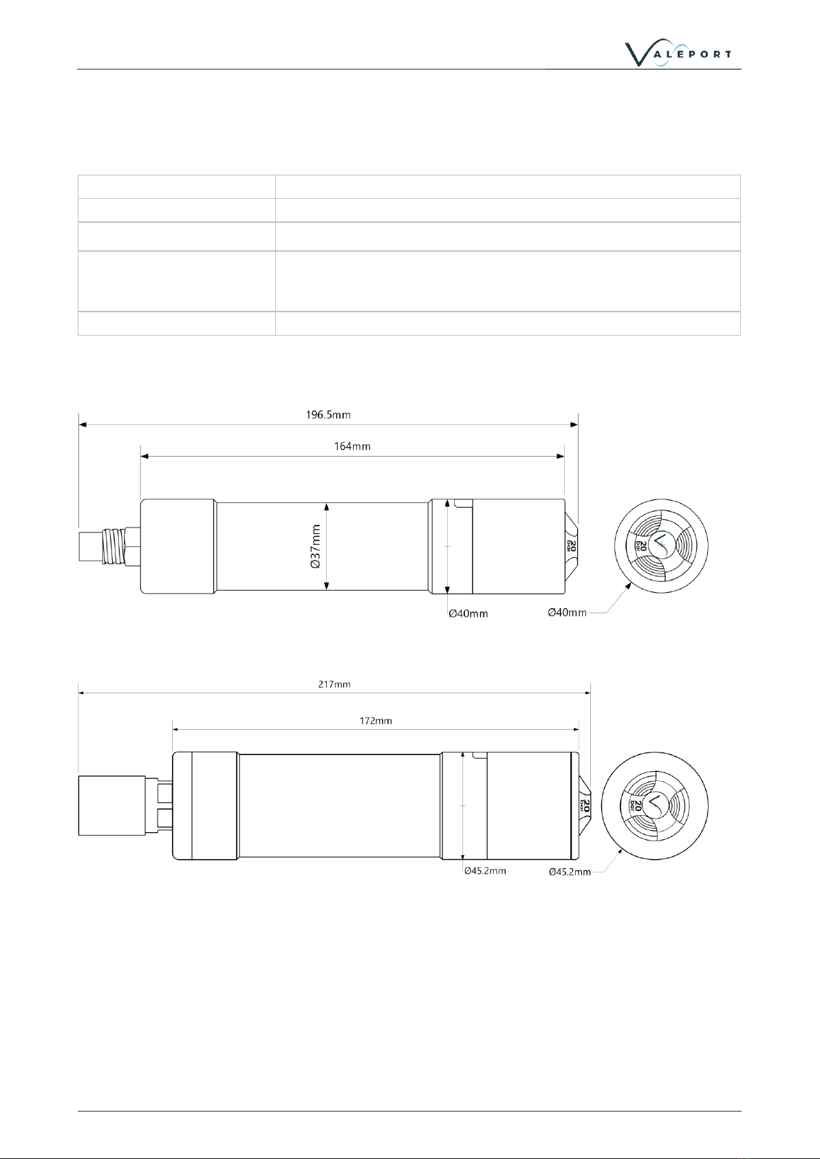
3.2 Dimensions - miniIPS 2.................................................................................................................... 4
3.3 Dimensions - miniIPS 2e.................................................................................................................. 4
4 Communications .................................................................................................................................... 5
4.1 Introduction .................................................................................................................................... 5
4.2 Serial Comms - RS 232 and RS485................................................................................................... 5
4.3 Ethernet .......................................................................................................................................... 6
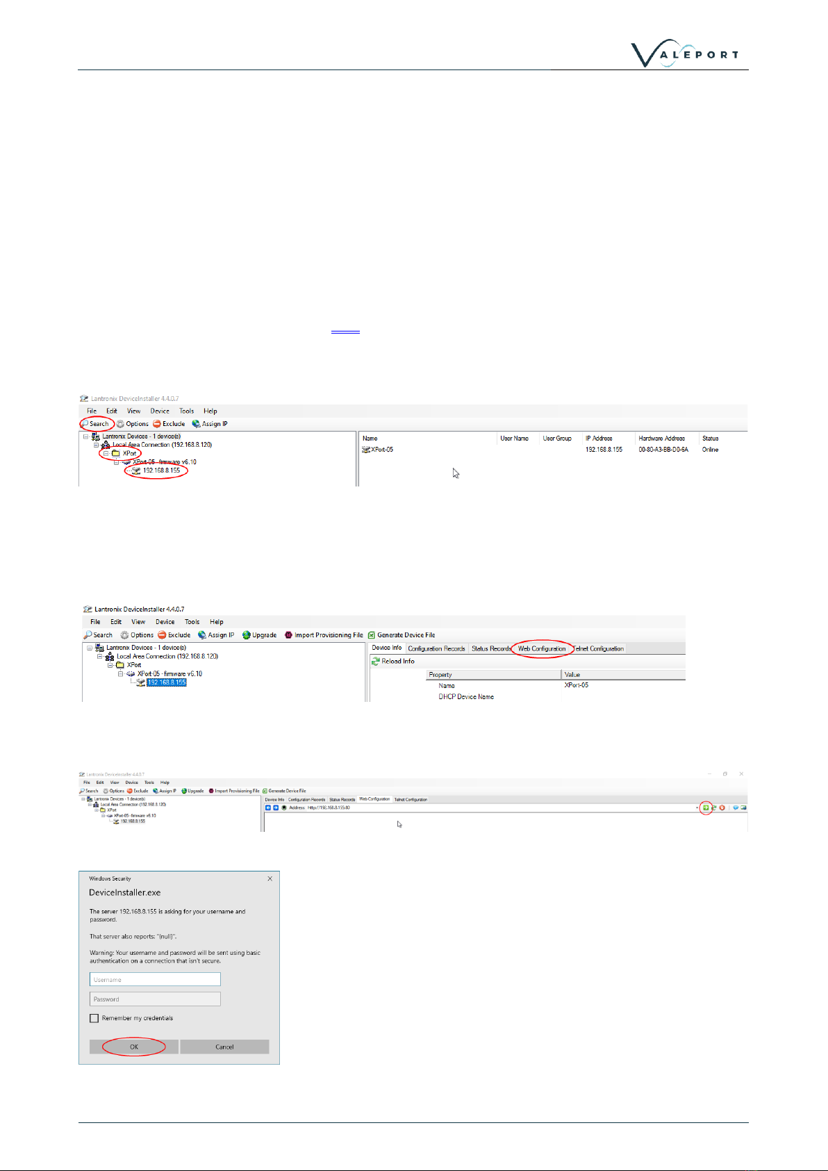
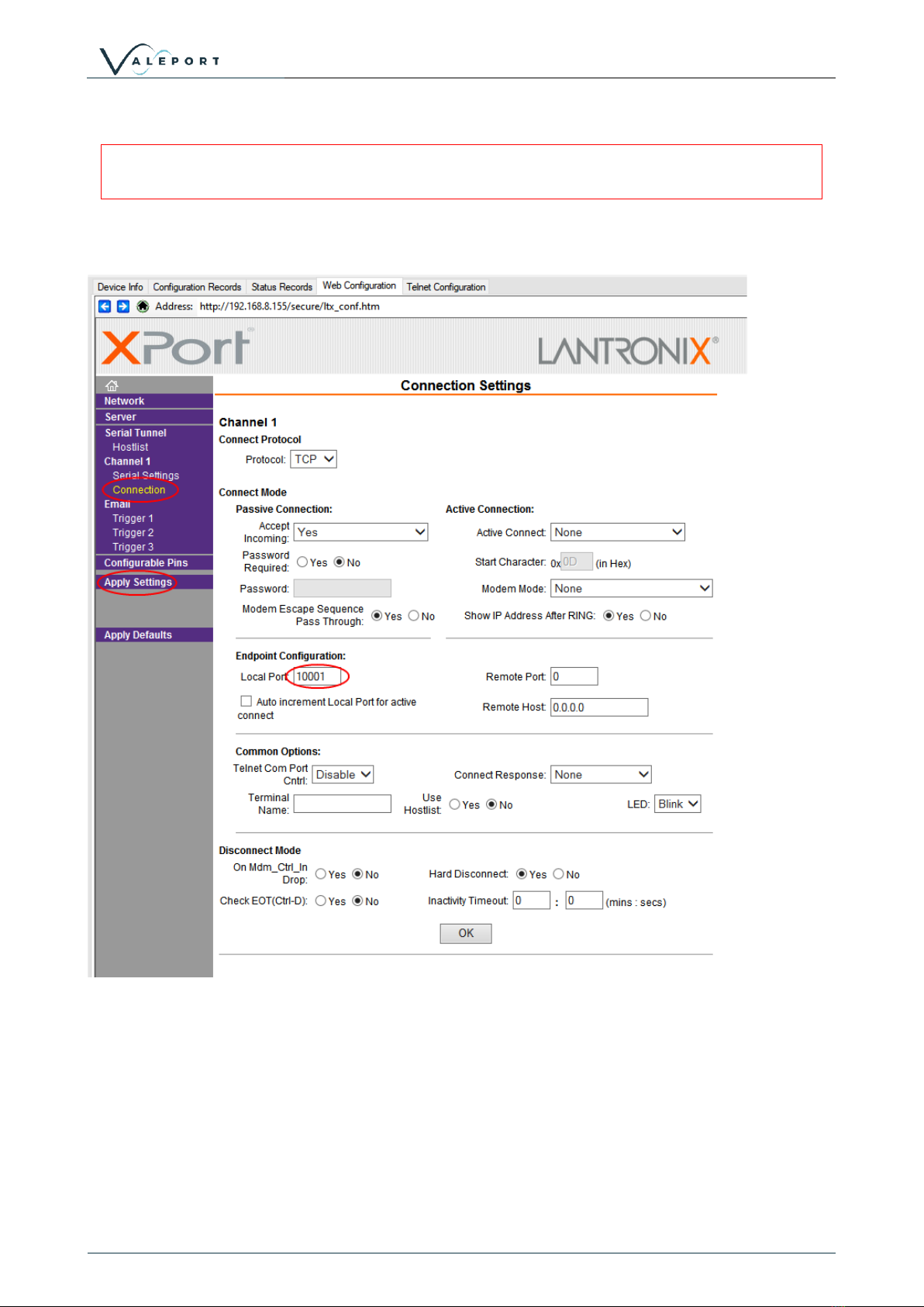
4.3.1 Setting up Ethernet Connectivity........................................................................................... 6
4.3.2 Operation with Datalog x2..................................................................................................... 9
4.3.3 Instrument Communications Setup ....................................................................................... 9
5 Setting Up the mniIPS2 ........................................................................................................................ 11
5.1 Start / Stop.................................................................................................................................... 11
5.1.1 Output Last Measured Reading ........................................................................................... 11
5.2 Welcome Message........................................................................................................................ 12
5.3 Warning Message ......................................................................................................................... 13
5.4 Error Flag....................................................................................................................................... 13
5.5 Sampling Modes............................................................................................................................ 14
5.6 Units.............................................................................................................................................. 15
5.6.1 Commands........................................................................................................................... 15
5.7 Pressure Tare ................................................................................................................................ 16
5.8 Set Latitude................................................................................................................................... 17
5.9 Standard Set Up ............................................................................................................................ 17
5.10 Information #Codes ...................................................................................................................... 18
6 Data Output Formats ........................................................................................................................... 19
6.1 Data String Formatting.................................................................................................................. 19
6.2 Format: Valeport CSV.................................................................................................................... 19
6.3 Format: Valeport (Standard) ......................................................................................................... 20
6.4 Format: Valeport NMEA ($PIPS).................................................................................................... 20
6.5 Format: Valeport NMEA ($PVIPS2) ............................................................................................... 21
6.6 Format: CSV .................................................................................................................................. 21
6.7 Format: Digiquartz ........................................................................................................................ 22
6.8 Format: Digiquartz CDL ................................................................................................................. 22
6.9 Format: Hypack............................................................................................................................. 22
6.10 Format: Impact SubSea................................................................................................................. 23
6.11 Modbus RTU over RS485............................................................................................................... 23

Contents
Page | c
©2020 –Valeport Ltd
7 Electrical............................................................................................................................................... 24
7.1 Power - miniIPS 2 .......................................................................................................................... 24
7.2 Power - miniIPS 2e ........................................................................................................................ 24
7.3 Wiring Information ....................................................................................................................... 24
7.3.1 Serial Connection................................................................................................................. 24
7.3.2 Ethernet Connection............................................................................................................ 24
8 Software............................................................................................................................................... 25
8.1 Setup Using DataLog X2 ................................................................................................................ 25
8.1.1 Interface to the miniIPS 2 .................................................................................................... 25
8.1.2 Configure the miniIPS 2 ....................................................................................................... 26
9 Setup Using Valeport Configure App.................................................................................................... 32
9.1 Interface the instrument............................................................................................................... 32
9.1.1 Valeport Configure Without an Instrument......................................................................... 32
9.2 Configure the Instrument.............................................................................................................. 33
10 Care & Maintenance ............................................................................................................................ 38
10.1 Calibration..................................................................................................................................... 38
10.1.1 Secondary Calibration.......................................................................................................... 38
11 Ordering and Part Numbers ................................................................................................................. 39
12 EU Declaration of Conformity - CE Marking ......................................................................................... 40
12.1 miniIPS2 ........................................................................................................................................ 41
12.2 miniIPS2e ...................................................................................................................................... 42
12.3 Interchangeable Pressure Module................................................................................................ 43

miniIPS2 and 2e Operating Manual: MANUAL-383434403-1
Page | 1
©2020 –Valeport Ltd
1Introduction
The Valeport miniIPS2 and 2e “Intelligent Pressure Sensor” builds on the success of the industry standard
miniIPS.
•The miniIPS2 operates over serial comms - RS232 and RS485.
•The miniIPS2e operates over Ethernet (TCP/IP).
Designed to measure water pressure and provide a real time output of that data in a number of formats
and units. The miniIPS2 and 2e are fitted with an Interchangeable, depth optimised, pressure sensor
allowing the most operationally suitable pressure sensor module to be fitted for the operational water
depth. To be used in a variety of subsea applications ROVs, construction survey, monitoring and
positioning operations, one of the key development drivers was to provide a cost effective alternative to
the use of resonant quartz pressure sensors. Using the very latest technology in temperature compensated
piezo-resistive transducers, the miniIPS2 and 2e offers several advantages over resonant quartz sensors,
with similar performance - cost, maintenance and operationally specific pressure ratings.
•Interchangeable pressure sensor module
-Pressure ranges from 10 to 600Bar (approx 100m to 6 000m water)
-Titanium diaphragm pressure sensor
▪No external diaphragms, oil reservoir or oil-filled tubes
-Long term calibration stability
-2 year recommended recalibration cycle
•Titanium housing
•RS232 or addressable RS485 data output
•ASCII and Modbus RTU output protocols
•Choice of calibrated data formats
•TEOS 10 seawater properties of water computation for depth calculation
•Choice of sampling modes

Sensors
©2020 –Valeport Ltd
Page | 2
2Sensors
2.1 Pressure Sensor
The miniIPS2 and 2e are fitted with the following sensors:
•A high accuracy, 0.01% of full scale, temperature compensated piezo-resistive pressure transducer.
•The Pressure Module is interchangeable
Sensor Type
Strain Gauge
Range:
individual modules
10, 20, 30, 50, 100, 200, 300, 400 or 600 Bar
1 bar is approximately equal to 10m depth
Resolution:
0.001% of full range
Accuracy:
±0.01% or full range
Response Time:
1 millisecond
2.2 Interchangeable Pressure Sensor Modules
The Interchangeable Pressure Sensor Modules can be swapped to best suit the operational depth of the
project. The accuracy of the sensor is a factor of the full-scale capability of the sensor - 0.01% and not the
measured pressure. A 600 Bar module will offer the same ± 0.60m accuracy at 6000m as it will at 250m
while a correctly selected 30 Bar Pressure Module, for an operation at 250m, will provide an accuracy ±
0.03m
Bar
Maximum Operational Depth
(metres)
Accuracy (0.01%)
(± metres)
10
100
0.01
20
200
0.02
30
300
0.03
50
500
0.05
100
1000
0.10
200
2000
0.20
300
3000
0.30
400
4000
0.40
600
6000
0.60
Prior to changing out a Pressure Module the mini IPS 2 or 2e should be thoroughly rinsed in fresh water and
dried.
A Pressure Module should ideally be changed in dry lab conditions but if this is not possible every effort
must be made to keep water out of the module socket. If water does get in, it must be dried before a
replacement module is fitted to protect the connector from corrosion.
A special tool is provided to unscrew the fitted module and screw its replacement securely into place.
Never use excessive force.

miniIPS2 and 2e Operating Manual: MANUAL-383434403-1
Page | 3
©2020 –Valeport Ltd
The three prongs should be carefully inserted into the lock screw cap of the Pressure Module and turned
counter-clockwise (when looking directly at the module) to loosen it. Keep turning until the Pressure
Module gently pops out of the socket. The tool will engage with the Pressure Module and allow you to very
gentle pull if required.
Before fitting a replacement Pressure Module check all surfaces for wear - especially the lock screw cap.
Check the O rings are clean and free of any debris, wear or damage. There is no need to grease the O rings.
The closing action of the system does not rely on surfaces sliding over one another and grease might attract
debris that would compromise the seal.
The replacement Pressure Module should be placed into the socket with the connector approximately lined
up with its pair. Fine adjustment is achieved by the shape of the module housing in the socket.
Engage the screw cap into the threads of the socket and then use the tool to tighten the Pressure Module
into place. The module should be screwed down until the shoulder of the lock screw cap is in line with the
shoulder of the titanium end-cap as shown below:
Do not over tighten.
Inside the transit case an additional transit case is provide for the Pressure Module to all it to be sent off for
calibration without the need to send the whole instrument.

Physical Characteristics
©2020 –Valeport Ltd
Page | 4
3Physical Characteristics
3.1 Materials
Housing & Bulkhead:
Titanium
Screw Cap:
Acetal
Transducer Diaphragm
Titanium
Connector:
miniIPS2: Standard is SubConn type MCBH6F (titanium)
miniIPS2e: Standard is SubConn type DBH13F (titanium)
Alternatives may be supplied on request
Weight:
<0.75kg (in air)
3.2 Dimensions - miniIPS 2
3.3 Dimensions - miniIPS 2e

miniIPS2 and 2e Operating Manual: MANUAL-383434403-1
Page | 5
©2020 –Valeport Ltd
4Communications
4.1 Introduction
Control of the miniIPS2 and 2e is achieved through the use of “# codes”, as described in the sections below.
All commands must be “sent” by pressing the Enter key
with the exception of the single ‘#’ character required to enter set up mode
4.2 Serial Comms - RS 232 and RS485
miniIPS2 is fitted with both RS232 and RS485 communications as standard. RS485 is enabled by grounding
a pin in the communications lead (refer to Wiring Section).
Protocol is 8 data bits, 1 stop bit, no parity, no flow control.
Baud rate is factory set to 115200. User may choose between 1200, 2400, 4800, 9600, 19200, 38400,
57600, 115200 and 230400.
Fast data rates and longer data string outputs may n\ot be possible with low baud rates

Communications
©2020 –Valeport Ltd
Page | 6
4.3 Ethernet
The miniIPS2e is fitted with a Transmission Control Protocol/Internet Protocol (TCP/IP) Ethernet module set
up in Dynamic Host Configuration Protocol (DHCP). This means the instrument will automatically be
assigned a IP address. Depending on how your router works, it should go back to that IP address each time
it is interfaced although this is not guaranteed unless you provide it with a fixed IP in the router
configuration.
4.3.1 Setting up Ethernet Connectivity
The miniIPS2e has a Lantronix Ethernet module that will need to be configured. You can download the
Lantronix Device Installer software from here.
Connect the miniIPS2e to the network and run the software. If the device is not found after a few
moments press Search, top left
Once the module has been found click on XPort to reveal the IP address - in the example above:
192.168.8.155
Click on the IP Address in the left hand panel to reveal more information in the right hand panel
Select Web Configuration
Select the green arrow to reveal the password entry dialogue
Do not enter a Username or Password - simply select OK

miniIPS2 and 2e Operating Manual: MANUAL-383434403-1
Page | 7
©2020 –Valeport Ltd
•Select Connection, ensure settings are similar to below
do not select or accept a Local Port number 23
Local Port number 23 is reserved for TelNet
•Select Apply Settings
•Perform a new search after the settings have been completed.

Communications
©2020 –Valeport Ltd
Page | 8
•Select Serial settings, Set Baud Rate on Channel 1 to 115200
•Apply settings
•Perform a new search after the settings have been completed and applied.
4.3.1.1 Fixed IP
To set a fixed IP address for the unit follow the wizard in the Lantronix App

miniIPS2 and 2e Operating Manual: MANUAL-383434403-1
Page | 9
©2020 –Valeport Ltd
4.3.2 Operation with Datalog x2
Load the latest version of Valeport's configuration software DataLog x2. It can be downloaded from here -
search for miniIPS2 then look for the software section towards the bottom of the page.
Setup the TCP Client windows to match the data from the Lantronix Device Installer. The instrument can be
configured using the software or with individual #commands as required.
4.3.3 Instrument Communications Setup
The following # commands need to be set as required to achieve the communications scenario required
Code
Description
#001;nn
Set RS485 address to any number from 01 to 99
leading 0 required for address numbers 1 to 9
#002
Read current address
#005;n
Set address mode On | Off
where n =
#005;0 (Off)
#005;1 (On)
In address mode, the miniIPS2 and 2e will only respond to commands prefixed by its
address, or the global address “00”
Example:
03:#028
miniIPS2 address “03”, begin sampling
Example:
00:#028
All miniIPS2 addresses, begin sampling
#006
Read Address Mode activation status
#059;xxxxxx
Set the miniIPS2 and 2e baud rate as required
Available baud rates are 1200, 2400, 4800, 9600, 19200, 38400, 57600, 115200,
230400
Example: #059;9600
#352,n
Enable | Disable # on Modbus - interrupts the instrument with a serial # if in Modbus
mode
#352;0 (disable)
#352;1 (enable)
#353
Read # on Modbus activation status
#700; n;n
Enables Modbus communications mode with parity on or off
Once entered into Modbus mode the miniIPS2 or 2e will begin to measure on the
measurement cycle.
#700;0;0 - Modbus disabled
#700;0;1 - Modbus disabled
#700;1;0 - Modbus No Parity
#700;1;1 - Modbus Even Parity
this function is password protected

Communications
©2020 –Valeport Ltd
Page | 10
Code
Description
#701
Read Modbus activation status
#702;nnn
Set RS 485 address to any number from 01 to 247
this function is password protected
#703
Read current address

miniIPS2 and 2e Operating Manual: MANUAL-383434403-1
Page | 11
©2020 –Valeport Ltd
5Setting Up the mniIPS2
5.1 Start / Stop
When power is applied to the miniIPS, it will immediately begin to operate according to the settings already
programmed. The most basic level of Stop / Start control is, therefore, by switching power on and off.
# Code
Description
#
When the instrument is running, the miniIPS2 and 2e may be put into set up mode
at any time by typing the ‘#’ character followed by the ENTER key. The device will
respond with a command prompt ‘>’ and wait the next instruction.
When interrupted an error is often seen. This is generated due to the <CR><LF>
usually associated with the # and should not be interpreted as a problem with the
uvSVX
A “watchdog” function is in operation within the miniIPS2 and 2e
If the unit is interrupted with the ‘#’ character, and no further command is received
for a period of 5 minutes, the sensor will automatically begin sampling data using the
existing settings
#028
Starts sampling in the mode set, or takes a single reading if unit is in “Single”
sampling mode.
5.1.1 Output Last Measured Reading
In order to read the last measured reading the command #015 can be used.
The data is output in the selected units and data telegram format.

Setting Up the mniIPS2
©2020 –Valeport Ltd
Page | 12
5.2 Welcome Message
When the miniIPS2 or 2e is put into a run mode (#028), if the welcome message is enabled (#209;1), it will
output a welcome message
Code
Description
#209;n
Enable | Disable the Welcome Message
#209;0 disables the warning
#210;1 enables the warning
#210
Read Welcome Message activation status
The message contains the following information
Field
Format
Setup Function
miniIPS2 or 2e Serial Number:
xxxxxxx
Pressure Module Serial Number:
xxxxxxx
PCB Serial Number:
xxxxxxxxxx
Firmware Version:
xxxxxxxx September 22 2020 11:42
Pressure Module Range:
xxxBar
Operating Mode:
x
#011
No of Samples:
xxx
#029
Sampling Rate:
xxxHz
#003
Output String Format:
x
#013
Calibrated Units:
x
#018
Tare Enabled:
x
#007
Tare Value:
xxxxxx (in units)
#009
instrument Address:
xx
#001
Latitude:
xx.xxx
#135
Primary Cal:
0.xxxe+00,0.yyye+00,1.zzze+00
Secondary Cal Enabled:
0
#038
Secondary Cal:
0.aaae+00,0.bbbe+00,0.ccce+00

miniIPS2 and 2e Operating Manual: MANUAL-383434403-1
Page | 13
©2020 –Valeport Ltd
5.3 Warning Message
If a Pressure Module is not fitted and the uvSVX is deployed, damage can be caused to the instrument. In
order to bring this situation to your notice a warning is transmitted on power up and putting the uvSVX into
run mode: #028 or the watch dog.
This message can be turned on or off
Code
Description
#220;n
Enable | Disable the Warning Message
#220;0 disables the warning
#120;1 enables the warning
#221
Reads the Warning Message activation status:
5.4 Error Flag
Code
Description
#035;nnnnn
Sets the value output in the output string when the Pressure | Depth value is in error
e.g. missing Pressure Module
Where n = a number from -100 000 to 100 000
Example:
#035;-9999
#036
Read the Error Flag
DataLog x2 showing a warning message that a Pressure Module is not fitted

Setting Up the mniIPS2
©2020 –Valeport Ltd
Page | 14
5.5 Sampling Modes
The miniIPS2 and 2e will operate in a number of different modes:
Code
Sampling Mode
Description
#011;0
HOLD
The miniIPS2 or 2e will be powered but make no observations
#028 will cause an observation to be taken but no data will be output
until a #015 command is sent to recover the last observation made.
#011;1
SINGLE
Single mode is effectively “Sample on Demand”
When instructed (#028), the sensor will observe and output the data
as a single observation
Note: If the start up message is enable it will be generated with each
observation
#011;2
CONTINUOUS
Data is observed and output at a fixed sampling rate from 1 to 100Hz
set by #003
#011;3
BURST FIXED
AVERAGE
Data is measured at the sampling rate (#003) for a number of samples
(#029)
The data set is then averaged before being output as a single
observation
The data set is cleared and a new set of data observed, averaged and
output
An instrument set to update at 32Hz with a dataset size of 32 will
output averaged data at 1Hz
#011;4
BURST MOVING
AVERAGE
Data is measured at the sampling rate (#003) for a number of samples
(#029)
The data set is then averaged before being output as a single
observation
The oldest observation is dropped and a new one added to the data
set
The data set is then averaged and output as a single observation
An instrument set to update at 32Hz with a dataset size of 32 will
output averaged data at 32Hz
#012
Read the Sampling Mode
#003;nn
Set the Sampling Rate
where xx = 1, 2, 4, 8, 16, 32, 64 or 100Hz
slow baud rates and long output strings can limit the sampling rate
#004
Read Sampling Rate
#029;nnn
Set the number of sample to be averaged
#030
Read the number of samples

miniIPS2 and 2e Operating Manual: MANUAL-383434403-1
Page | 15
©2020 –Valeport Ltd
5.6 Units
•The default output units for the miniIPS2 and 2e are deciBar (dBar), equivalent to 0.1Bar, or
approximately 1m of seawater
•The miniIPS2 and 2e can also output pressure in a number of different units
•It is also possible to present the data in units of metres or feet of seawater
-calculated using the TEOS 10 Simple Pressure / Depth relationship, which assumes “standard” water
density. A Latitude is required - see Set Latitude
5.6.1 Commands
# Code
Description
#018;n
Set calibrated units as follows, where n = 1 to 6
1 = mBar (m) 2 = dBar (d)
3 = Bar (B) 4 = Metres (M)
5 = Feet (f) 6 = PSI (P)
Example: #018;3
sets the units to Bar
#019
Read unit set
#020;n
Enable / Disable unit character in the Valeport output string, where n=
0=hide units in valeport string
1=display units in valeport string
Available in the following data string formats:
Valeport NMEA ($PIPS) | Valeport Standard | Valeport NMEA ($PVIPS2) | Impact
SubSea
#021
Read units activation status - 0 = OFF | 1 = ON
All output formats are affected by changing the output units.

Setting Up the mniIPS2
©2020 –Valeport Ltd
Page | 16
5.7 Pressure Tare
The Interchangeable pressure sensor fitted in the miniIPS2 and 2e measures absolute pressure, that is, it
includes atmospheric pressure. The pressure Tare function allows the atmospheric pressure (as measured
by the sensor, normally before deployment) to be removed from the observations so the output is simply
the pressure of water.
The Tare function is performed after any User Cal is applied and conversion to depth if the units selected are in
feet (f) or metres (M).
If you set the Tare in one unit it will be held in that unit until re-observed regardless of whether you change the
unit subsequently
By taking a Tare reading at any fixed point in the water column, readings will then be output relative to that
point
•The pressure Tare observation should be taken with the sensor in the same orientation as it will be
deployed (horizontal, pointing up or pointing down) to negate any effects of the weight of the sensing
element itself
-Whilst this effect is small, it is an unnecessary contribution to the error budget
Code
Description
#007
Enable | Disable pressure Tare function
#007;0 (disable)
#007;1 (enable)
#008
Read pressure Tare status
#009;0
Auto Tare (observes current pressure reading and programs the Tare value)
#009;nnnn.nnn
Sets specific Tare in dBar or Bar (max resolution of 0.000001) depending on units
selected by #018 command.
Example:
#009;10.325 sets tare to 10.325dBar
#010
Read the current Tare value in the units set at the time it was observed
If the Pressure Module, units or the calibration are changed the Tare value must be re-observed

miniIPS2 and 2e Operating Manual: MANUAL-383434403-1
Page | 17
©2020 –Valeport Ltd
5.8 Set Latitude
The Latitude is required for an accurate pressure / depth conversion - the relationship is partially
dependent on local gravity, which varies with distance from the equator.
Positive / negative signing for North / South of the equator is not relevant
# Code
Description
#135;nn.nnn
Sets the local operating latitude in decimal degrees
Example: #135;50.426
Sets latitude to 50.426° (50° 25’ 34”)
#136
Read the Latitude set in the instrument
5.9 Standard Set Up
A customer can request a Standard Set Up script to set their instruments up in a particular manner, output
instrument information, perform variance checks and set to run mode etc..
Please contact Valeport for further information
# Code
Description
#999;n
Set an instrument up as specified by a script
Where n = your script number
#999;0 will set the instrument back to factory default settings
This manual suits for next models
1
Table of contents
Other Valeport Accessories manuals

Valeport
Valeport SWiFT SVP User manual

Valeport
Valeport VRS20 User manual

Valeport
Valeport Hyperion 0901001 User manual

Valeport
Valeport miniIPS User manual

Valeport
Valeport Hyperion Chlorophyll a User manual

Valeport
Valeport miniSVS User manual

Valeport
Valeport UV-SVP User manual

Valeport
Valeport miniSVS User manual

Valeport
Valeport uvSVX User manual