Valeport uvSVX User manual

uvSVX Operating Manual
Document ID
MANUAL-857569191-10
Date:
September 2020
This confidential document was prepared by the staff of Valeport Limited, the Company, and is the
property of the Company, which also owns the copyright therein. All rights conferred by the law of the
copyright and by virtue of international copyright conventions are reserved to the Company. This document
must not be copied, reprinted or reproduced in any material form, either wholly or in part, and the
contents of this document, and any method or technique available there from, must not be disclosed to
any other person whatsoever without the prior written consent of the Company.
© 2020 Valeport Ltd
Valeport Ltd
St Peter's Quay
Totnes TQ9 5EW
United Kingdom
Phone:
email:
Web:
As part of our policy of continuous development, we reserve the right to alter, without prior notice, all
specifications, designs, prices and conditions of supply for all our equipment

Contents
Page | b
© 2020 –Valeport Ltd
Contents
1 Introduction ........................................................................................................................................... 1
2 Sensors................................................................................................................................................... 2
2.1 Sound Velocity Measurement......................................................................................................... 2
2.2 Temperature ................................................................................................................................... 2
2.3 Pressure .......................................................................................................................................... 2
2.3.1 Interchangeable Pressure Sensor Modules............................................................................ 3
2.4 Calculated Parameters.................................................................................................................... 5
2.4.1 Calculated Conductivity ......................................................................................................... 5
2.4.2 Calculated Salinity.................................................................................................................. 5
2.4.3 Calculated Density ................................................................................................................. 5
3 Physical Characteristics .......................................................................................................................... 6
3.1 Materials......................................................................................................................................... 6
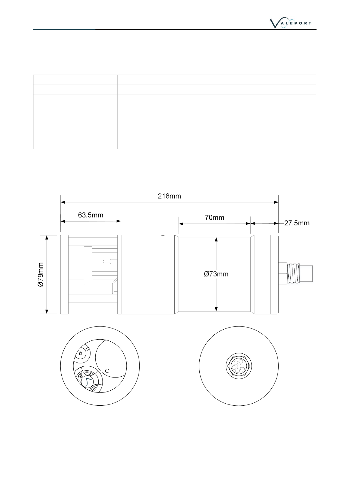
3.2 Dimensions ..................................................................................................................................... 6
4 Communications .................................................................................................................................... 7
4.1 Serial Comms - RS 232 and RS485................................................................................................... 7
4.2 Ethernet .......................................................................................................................................... 8
4.2.1 Setting up Ethernet Connectivity........................................................................................... 8
4.2.2 Operation with Datalog x2................................................................................................... 11
4.3 uvSVX Communications Setup ...................................................................................................... 12
5 Setting Up the uvSVX ........................................................................................................................... 13
5.1 Start / Stop.................................................................................................................................... 13
5.1.1 Output Last Measured Reading ........................................................................................... 13
5.2 Information #Codes ...................................................................................................................... 14
5.3 Sampling Modes............................................................................................................................ 15
5.4 Pressure Tare ................................................................................................................................ 15
5.5 Error Flag....................................................................................................................................... 16
5.6 Warning Message ......................................................................................................................... 16
5.7 Pressure | Depth Units.................................................................................................................. 17
5.8 Set Latitude................................................................................................................................... 17
5.9 DASH Formula............................................................................................................................... 18
5.10 User Calibration ............................................................................................................................ 18
6 Data Output Formats ........................................................................................................................... 19
6.1 Data String Formatting.................................................................................................................. 19
6.2 CSV Format ................................................................................................................................... 20
6.3 Valeport NMEA ($PVSVX).............................................................................................................. 21
6.4 Data String #1................................................................................................................................ 22
6.5 Modbus RTU ................................................................................................................................. 22
7 Electrical............................................................................................................................................... 23
7.1 Power uvSVX................................................................................................................................. 23
7.2 Power uvSVXe ............................................................................................................................... 23
7.3 Wiring Information ....................................................................................................................... 23

Contents
© 2020 –Valeport Ltd
Page | c
8 Software............................................................................................................................................... 24
8.1 Setup Using DataLog X2 ................................................................................................................ 24
8.1.1 Interface to the uvSVX ......................................................................................................... 24
8.1.2 Configure the uvSVXminiIPS 2 ............................................................................................. 25
8.2 Setup Using the SetUp App ........................................................................................................... 31
8.2.1 Interface to the uvSVX ......................................................................................................... 31
8.2.2 Configure the Instrument .................................................................................................... 32
9 Care & Maintenance ............................................................................................................................ 36
9.1 Calibration..................................................................................................................................... 37
10 Ordering and Part Numbers ................................................................................................................. 38
11 EU Declaration of Conformity - CE Marking ......................................................................................... 39
11.1 uvSVX ............................................................................................................................................ 40
11.2 Interchangeable Pressure Module ................................................................................................ 41

uvSVX Operating Manual: MANUAL-857569191-10
Page | 1
© 2020 –Valeport Ltd
1Introduction
Aimed primarily at the underwater vehicle market, the uvSVX is a compact direct reading instrument that
outputs a selectable, fixed data string at up to 60Hz of Sound Velocity, Temperature, Depth and optionally,
Salinity and Density calculated with Valeport’s proprietary DASH formula. High accuracy data is assured
with the added bonus of Valeport’s unique interchangeable pressure module that allows customers to
maximise operational specific depth requirements. This innovative pressure module, with integral
calibration, can be changed in a couple of minutes without opening the instrument.
There are two communication options of the uvSVX, RS232 / RS485 and Ethernet
To be used in a variety of subsea applications ROVs, construction survey, monitoring and positioning
operations, one of the key development drivers was to provide a cost-effective alternative to the use of
resonant quartz pressure sensors. Using the very latest technology in temperature compensated piezo-
resistive transducers, the uvSVX offers several advantages over resonant quartz sensors, with similar
performance - cost, maintenance and operationally specific pressure ratings.
Valeport's DASH equations are included in the uvSVX, as standard and provide a real-time water density
output.
•Interchangeable Pressure Sensor Module
-Pressure ranges from 10 to 600Bar (approx 100m to 6 000m water)
-Titanium diaphragm pressure sensor
▪No external diaphragms, oil reservoir or oil-filled tubes
-Long term calibration stability witha 2 year recommended recalibration cycle
•Sound Sound Speed
-Valeport's industry standard 25mm baseline, Digital Time of Flight sound speed sensor
•Temperature
-fast response PRT
•Titanium housing
•RS232 or RS485 (addressable) data output
•ASCII and Modbus RTU output protocols
•Choice of calibrated data output format at a sampling rate of up to 60Hz
•TEOS 10 seawater properties of water computation for depth calculation
uvSVX - Sound Speed, Pressure and Temperature
for underwater vehicles

Sensors
© 2020 –Valeport Ltd
Page | 2
2Sensors
2.1 Sound Velocity Measurement
Utilising Valeport's latest design for the world's most accurate sound velocity sensor, each measurement is
made using a single pulse of sound travelling over a precisely known distance, so is independent of the
inherent calculation errors present in CTD calculated data. Valeport's unique digital signal processing
technique virtually eliminates signal noise and gives an almost instantaneous response; the digital
measurement is also entirely linear, giving predictable performance under all conditions.
Range:
1375 - 1900m/s
Resolution:
0.001m/s
Accuracy:
±0.020m/s
2.2 Temperature
The uvSVX is fitted with an accurate, fast response Platinum Resistance Thermometer (PRT) temperature
sensor.
Type:
PRT
Range:
-5°C to +35°C
Accuracy:
±0.01°C
Resolution:
0.001°C
2.3 Pressure
The uvSVX is fitted with a high accuracy, 0.01% of full scale, temperature compensated piezo-resistive
pressure transducer.
The Pressure Module is interchangeable
Type:
Strain Gauge
Range:
individual modules
10, 30, 50, 100, 200, 300, 400 or 600 Bar
1 bar is approximately equal to 10m depth
Resolution:
0.001% of full range
Accuracy:
±0.01% or full range
Response Time:
1 milliseconds

uvSVX Operating Manual: MANUAL-857569191-10
Page | 3
© 2020 –Valeport Ltd
2.3.1 Interchangeable Pressure Sensor Modules
The Interchangeable Pressure Sensor Modules can be swapped to best suit the operational depth of the
project. The accuracy of the sensor is a factor of the full-scale capability of the sensor - 0.01% and not the
measured pressure. A 600 Bar module will offer the same ± 0.60m accuracy at 6000m as it will at 300m
while a correctly selected 30 Bar Pressure Module, for an operation at 300m, will provide an accuracy ±
0.03m
Bar
Approximate maximum
operational depth
metres
Accuracy (0.01%)
± metres
10
100
0.01
20
200
0.02
30
300
0.03
50
500
0.05
100
1000
0.10
200
2000
0.20
300
3000
0.30
400
4000
0.40
600
6000
0.60
Prior to changing out a Pressure Module the uvSVX should be thoroughly rinsed in fresh water and dried.
A Pressure Module should ideally be change in dry lab conditions but if this is not possible every effort must
be made to keep water out of the module socket. If water does get into the socket it must be dried before
a module is fitted to protect the connector from corrosion.
A special tool is provided to unscrew the fitted module and screw its replacement securely into place.
Never use excessive force. The design allows the Pressure Module to be swapped out without the need to
remove the protection cage of the uvSVX.
The three prongs should be carefully inserted into the black screw cap of the Pressure Module and turned
counter-clockwise (when looking directly at the module) to loosen it. Keep turning until the Pressure
Module gently pops out of the socket. The tool will engage with the Pressure Module and allow you to very
gentle pull if required.
Before fitting a replacement Pressure Module, check all surfaces for ware - especially the screw cap. Check
the O ring is clean and free of any ware or damage. There is no need to grease the O ring. The closing
action of the system does not rely on surfaces sliding over one another and grease might attract debris that
would compromise the seal.
The replacement Pressure Module should be placed into the socket with the connector approximately lined
up with its pair in the socket. Fine adjustment is achieved by the shape of the module housing in the
socket. If the Pressure Module is misaligned it will not tighten smoothly and should be removed and
turned by 180°.

Sensors
© 2020 –Valeport Ltd
Page | 4
Engage the screw cap into the threads of the socket and then use the tool to tighten the Pressure Module
into place. The module should be screwed down until the shoulder of the black screw cap is in line with the
shoulder of the titanium end-cap as shown below:
Inside the transit case an additional transit case is provided for the Pressure module to allow it to be
returned to Valeport for calibration without the need to send the whole instrument.

uvSVX Operating Manual: MANUAL-857569191-10
Page | 5
© 2020 –Valeport Ltd
2.4 Calculated Parameters
From directly measured sound velocity, temperature and pressure, the uvSVX calculates Conductivity,
Salinity and Density using a proprietary Valeport algorithm developed from extensive laboratory and
fieldwork data sets.
2.4.1 Calculated Conductivity
Accuracy:
±0.05 mS/cm
Resolution:
0.001 mS/cm
2.4.2 Calculated Salinity
Accuracy:
±0.05 PSU
Resolution:
0.001 PSU
2.4.3 Calculated Density
Accuracy:
±0.05 kg/m3
Resolution:
0.001 kg/m3

Physical Characteristics
© 2020 –Valeport Ltd
Page | 6
3Physical Characteristics
3.1 Materials
Housing & Bulkhead:
Titanium
Screw Cap:
Acetal
Pressure Transducer
Diaphragm
Titanium
Connector:
uvSVX: Standard is SubConn type MCBH6F (titanium)
uvSVXe: Standard is SubConn type DBH13F (titanium)
Alternatives may be supplied on request
Weight:
<1.75kg (in air)
3.2 Dimensions

uvSVX Operating Manual: MANUAL-857569191-10
Page | 7
© 2020 –Valeport Ltd
4Communications
Control of the uvSVX is achieved through the use of “# codes”, as described below.
All commands must be “sent” by pressing the Enter key
with the exception of the single ‘#’ character required to enter set up mode
4.1 Serial Comms - RS 232 and RS485
The uvSVX is fitted with both RS232 and RS485 communications as standard. RS485 is enabled by
grounding a pin in the communications lead (refer to Wiring Section).
Protocol is 8 data bits, 1 stop bit, no parity, no flow control.
RS232 comms have been tested over 200m of cable. Successful operation over this distance will depend on
the quality of cable. Contact Valeport for more information.
Baud rate is factory set to 115200. User may choose between 2400, 4800, 9600, 19200, 38400, 57600,
115200 and 230400.
Fast data rates and longer data string outputs may not be possible with low baud rates

Communications
© 2020 –Valeport Ltd
Page | 8
4.2 Ethernet
The uvSVXe is fitted with a Transmission Control Protocol/Internet Protocol (TCP/IP) Ethernet module set
up in Dynamic Host Configuration Protocol (DHCP). This means the instrument will automatically be
assigned an IP address. Depending on how your router works, it should go back to that IP address each time
it is interfaced although this is not guaranteed unless you provide it with a fixed IP in the router
configuration.
4.2.1 Setting up Ethernet Connectivity
The uvSVXe has a Lantronix Ethernet module that will need to be configured. You can download the
Lantronix Device Installer software from here.
Connect the uvSVXe to the network and run the software. If the device is not found after a few moments
press Search, top left
Once the module has been found click on XPort to reveal the IP address - in the example above:
192.168.8.155
Click on the IP Address in the left-hand panel to reveal more information in the right-hand panel
Select Web Configuration
Select the green arrow to reveal the password entry dialogue
Do not enter a Username or Password - simply select OK

uvSVX Operating Manual: MANUAL-857569191-10
Page | 9
© 2020 –Valeport Ltd
Select Connection, ensure settings are similar to below
Do not select or accept a Local Port number 23
Local Port number 23 is reserved for TelNet
Select Apply Settings
Perform a new search after the settings have been completed.

Communications
© 2020 –Valeport Ltd
Page | 10
Select Serial settings, Set Baud Rate on Channel 1 to 115200
Apply settings
Perform a new search after the settings have been completed and applied.
4.2.1.1 Fixed IP
To set a fixed IP address for the unit follow the wizard in the Lantronix App

uvSVX Operating Manual: MANUAL-857569191-10
Page | 11
© 2020 –Valeport Ltd
4.2.2 Operation with Datalog x2
Load the latest version of Valeport's configuration software DataLog x2. It can be downloaded from here.
Search for uvSVX then look for the software section towards the bottom of the page.
Setup the TCP Client windows to match the data from the Lantronix Device Installer. The instrument can be
configured using the software or with individual #commands as required.

Communications
© 2020 –Valeport Ltd
Page | 12
4.3 uvSVX Communications Setup
The following # commands need to be set as required to achieve the communications scenario required
Code
Description
#005;n
Set address mode On | Off
where n = 0 or 1
#005;0 (Off)
#005;1 (On)
In address mode, the uvSVX will only respond to commands prefixed by its
address, or the global address “00”
Example:
03:#028
uvSVX address “03” begin sampling
Example:
00:#028
All uvSVX addresses begin sampling
this function is password protected
#006
Read address mode activation status
#033;nn
Set uvSVX RS485 | Modbus address to any number from 01 to 99
this function is password protected
#034
Read address
#059;nnnnnn
Set the baud rate in the Instrument - factory set to 115200
where nnnnnn = 2400, ......, 230400
this function is password protected
#352,n
Enable | Disable # on Modbus
interrupts the instrument with a serial # if in Modbus mode
#352;0 (disable)
#352;1 (enable)
this function is password protected
#353
read # on Modbus activation status
#700; n;n
Enables Modbus communications mode with parity on or off.
Once entered into Modbus mode the uvSVX will begin to measure on the
measurement cycle.
#700;0;0 - Modbus disabled
#700;0;1 - Modbus disabled
#700;1;0 - Modbus No Parity
#700;1;1 - Modbus Even Parity
this function is password protected
#701
Read Modbus activation status

uvSVX Operating Manual: MANUAL-857569191-10
Page | 13
© 2020 –Valeport Ltd
5Setting Up the uvSVX
5.1 Start / Stop
When power is applied to the uvSVX, it will immediately begin to operate according to the settings already
programmed. The most basic level of Start / Stop control is, therefore, by switching power on and off.
A Welcome message is transmitted:
To put the uvSVX into run mode:
Code
Description
#028
Starts sampling in the mode set, or takes a single reading if unit is in “Single”
sampling mode.
#
When the instrument is running, the uvSVX may be put into set up mode at any
time by typing the ‘#’ character. The device will respond with a command prompt
‘>’ and wait the next instruction.
When interrupted an error is often seen. This is generated due to the <CR><LF>
usually associated with the # and should not be interpreted as a problem with the
uvSVX
A “watchdog” function is in operation within the uvSVX
If the unit is interrupted with the ‘#’ character, and no further command is received for a
period of 5 minutes, the sensor will automatically begin sampling data using the existing
settings
5.1.1 Output Last Measured Reading
In order to read the last measured reading the command #015 can be used.
The data is output in the selected units and data telegram format.

Setting Up the uvSVX
© 2020 –Valeport Ltd
Page | 14
5.2 Information #Codes
The following commands will cause the sensor to report back various pieces of information, as described.
#nnn to be followed by <CR><LF>:
# Code
Description
#003
Read uvSVX serial number
#006
Read address mode activation status
#010
Read Tare value
#012
Read Tare activation status
#014
Read firmware version number
#017
Read the instrument Latitude
#023
Read the SV calibration coefficients
#027
Read the data string delimiter
#032
Read calibration mode
#034
Read RS485/Modbus address value
#040
Read sampling mode
#043
Read leading separator activation status
#045
Read trailing separator activation status
#051
Read the number of samples in the dataset for averaging
#053
Read the pressure|depth units
#084
Read the number of decimal places in the pressure|depth field
#086
Read the User pressure calibration coefficients
#088
Read the temperature calibration coefficients
#089
Read the output string format
#096
Read the sampling frequency
#114
Read the FPGA firmware
#117
Read the pressure|depth error message
#121
Read DASH equations activation status
#138
Read last SV and Temperature calibration date
#200
Read Pressure Module serial number
#202
Read Pressure Module maximum pressure rating
#209
Read the DataMatrix Code (Pressure Module Serial Number)
#221
Read is warning message activation status
#353
Read '#' character to leave Modbus mode activation status (to use # codes with 8N1
framing)
If this mode is enabled do not use address 0x23 for Modbus
#501
Read the Calibration history for Temperature sensor
#502
Read the Calibration history for SV sensor
#511
Read User Calibration activation status
#701
Read Modbus activation status and parity status

uvSVX Operating Manual: MANUAL-857569191-10
Page | 15
© 2020 –Valeport Ltd
5.3 Sampling Modes
The uvSVX will operate in a number of different modes, only one is for regular use - Continuous
Contact Valeport if you have a special requirement
# Code
Sampling Mode
Description
#039;1
Continuous
Data is observed and output at a fixed sampling rate from 1 to 64Hz set by
#095
# Code
Description
#095;xx
Set the sampling rate where xx = 1, 2, 4, 8, 16, 32 or 64Hz
#096
Read sampling rate
Slow baud rates and long output strings can limit the sampling rate
5.4 Pressure Tare
The Interchangeable pressure sensor fitted in the uvSVX measures absolute pressure, that is, it includes
atmospheric pressure. The pressure Tare function allows the atmospheric pressure (as measured by the
sensor, normally before deployment) to be removed from the observations so the output is simply the
pressure of water.
By taking a TARE reading at any fixed point in the water column, readings will then be output relative to that point
The pressure Tare observation should be taken with the sensor in the same orientation as it will be
deployed (horizontal, pointing up or pointing down) to negate any effects of the weight of the sensing
element itself
Whilst this effect is small, it is an unnecessary contribution to the error budget
Code
Description
#009;0
Auto TARE
observe current pressure and program it as current TARE value
#009;nnnn.nnn
Set manual TARE in dBar or Bar (max resolution of 0.000001) depending on units
selected by #020 command.
Example:
#009;10.325 sets TARE to 10.325dBar
#010
read current Tare value in the units set at the time it was observed
#011;n
Enable | Disable pressure tare function
#011;0 (disable) the tare value is not subtracted from the measured pressure
#011;1 (enable) the tare value is subtracted from the measured pressure
#012
read pressure Tare activation status - 1 (Enabled) | 0 (Disabled)
If the pressure | depth units or calibration are changed the Tare value must be re-observed

Setting Up the uvSVX
© 2020 –Valeport Ltd
Page | 16
5.5 Error Flag
Code
Description
#116;n
Sets the value output in the CSV data string when the Pressure | Depth value is in
error e.g. missing Pressure Module
Where n = 1, 2 or 3
0 = 0.000
1 = -99999
2 = ERROR
#117
Read the Error Flag
5.6 Warning Message
If a Pressure Module is not fitted and the uvSVX is deployed, damage can be caused to the instrument. In
order to bring this situation to your notice a warning is transmitted on power up and putting the uvSVX into
run mode: #028 or the watch dog.
This message can be turned on or off
Code
Description
#220;n
Enable | Disable the Warning Message
#220;0 disables the warning
#120;1 enables the warning
#221
Reads the Warning Message activation status:
DASH computation will be erroneous if a pressure term is not available
DataLog x2 showing a warning message that a Pressure Module is not fitted

uvSVX Operating Manual: MANUAL-857569191-10
Page | 17
© 2020 –Valeport Ltd
5.7 Pressure | Depth Units
It is also possible to present the data in units of metres or feet of seawater
calculated using the TEOS 10 Simple Pressure / Depth relationship, which assumes “standard” water
density
Local Latitude is required (#016;nn.nnn)
Code
Description
#052;n
Set calibrated units as follows
where n=
0 = dBar (d)
1 = Metres (M)
2 = Feet (f)
Example: #052;1
sets the units to metres (M)
#053
Read pressure unit set
#083;n
Set the number of decimal places for pressure | depth output
where n = 1 to 3
#084
Read the number of decimal points in pressure |depth output
5.8 Set Latitude
This is required for an accurate pressure / depth conversion - the relationship is partially dependent on
local gravity, which varies with distance from the equator
Code
Description
#016;nn.nnn
Set the local Latitude in decimal degrees
Positive / negative signing for North / South of the equator is not relevant
Example: #016;50.426
Sets latitude to 50.426° North (50° 25’ 34”)
#017
Read the Latitude set in the instrument
Other manuals for uvSVX
1
This manual suits for next models
1
Table of contents
Other Valeport Accessories manuals

Valeport
Valeport miniIPS2 User manual

Valeport
Valeport VRS20 User manual

Valeport
Valeport SWiFT SVP User manual

Valeport
Valeport Hyperion 0901001 User manual

Valeport
Valeport miniSVS User manual

Valeport
Valeport miniSVS User manual

Valeport
Valeport UV-SVP User manual

Valeport
Valeport Hyperion Chlorophyll a User manual

Valeport
Valeport miniIPS User manual