Valeport VRS20 User manual

VRS20 Radar Level Gauge
Operating Manual
Document ID
MANUAL-477767835-1
Date:
November 2020
This confidential document was prepared by the staff of Valeport Limited, the Company, and is the
property of the Company, which also owns the copyright therein. All rights conferred by the law of
the copyright and by virtue of international copyright conventions are reserved to the Company.
This document must not be copied, reprinted or reproduced in any material form, either wholly or in
part, and the contents of this document, and any method or technique available there from, must
not be disclosed to any other person whatsoever without the prior written consent of the Company.
© 2020 Valeport Ltd
Valeport Ltd
St Peter's Quay
Totnes TQ9 5EW
United Kingdom
Phone:
email:
Web:
+44 1803 869292
sales@valeportwater.co.uk
www.valeportwater.co.uk
As part of our policy of continuous development, we reserve the right to alter, without prior notice,
all specifications, designs, prices and conditions of supply for all our equipment

Contents
©2020 –Valeport Ltd
Page | b
Contents
1 Introduction.............................................................................................................................1
1.1 Description.......................................................................................................................1
1.2 Features...........................................................................................................................1
1.3 Dimensions......................................................................................................................1
1.4 Specifications...................................................................................................................1
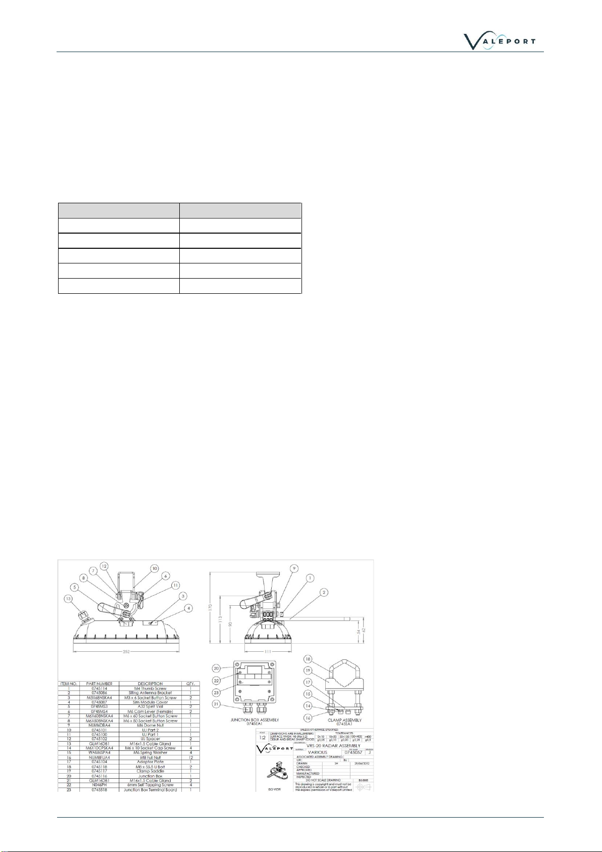
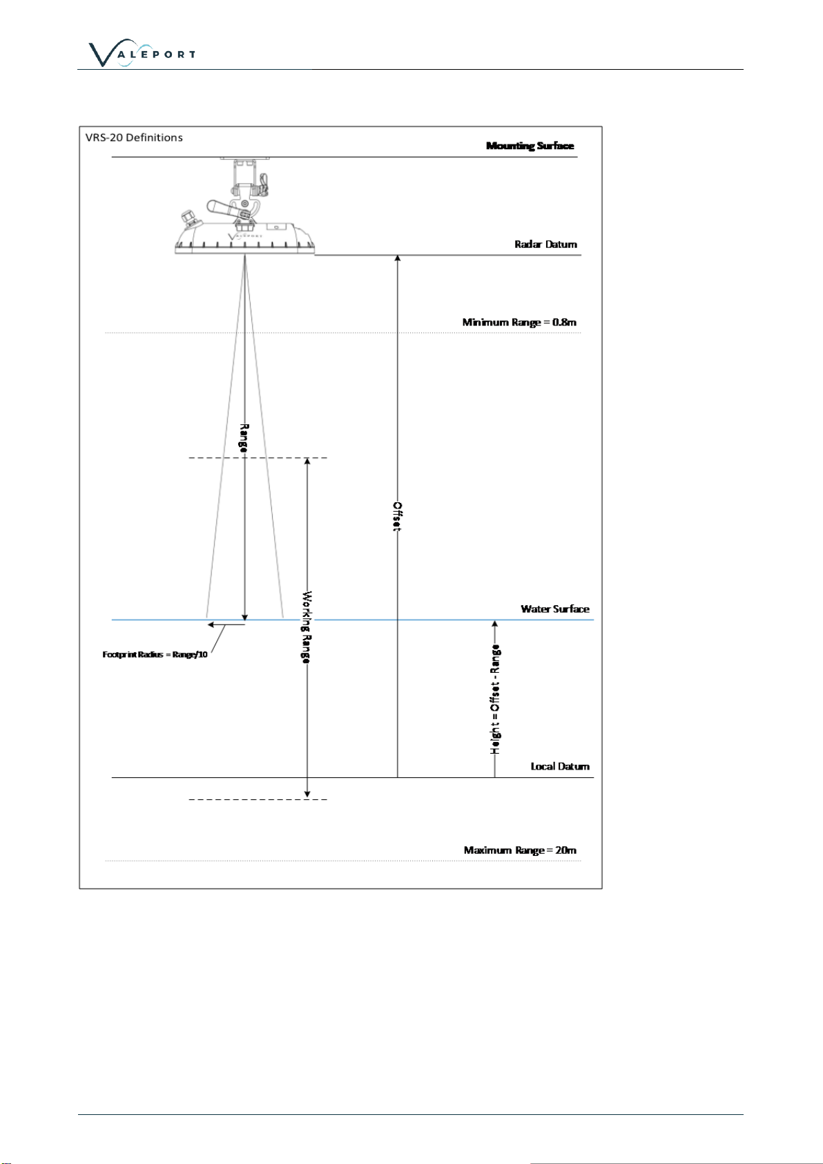
2 Installation..............................................................................................................................2
2.1 Tool Requirements...........................................................................................................2
2.2 Mounting on a Boom........................................................................................................4
2.3 Direct Mounting................................................................................................................5
2.4 Levelling...........................................................................................................................5
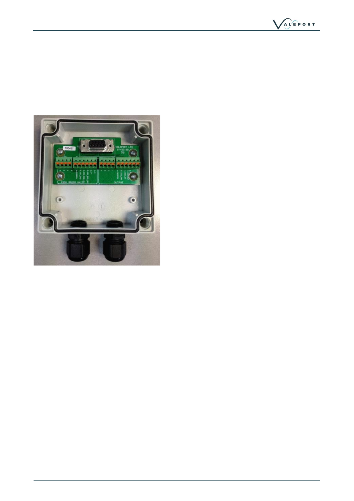
2.5 Wiring...............................................................................................................................6
2.5.1 Junction box ............................................................................................................6
3 Communications.....................................................................................................................7
3.1 RS232 Communications...................................................................................................7
3.2 RS485 Communications...................................................................................................7
3.2.1 RS485 Address Mode..............................................................................................7
3.3 SDI12 Communications....................................................................................................8
4 Data .....................................................................................................................................10
4.1 Stand Alone Data Format...............................................................................................10
4.2 Data Status....................................................................................................................10
5 Sampling modes...................................................................................................................11
5.1 Sampling Principles........................................................................................................11
5.2 Operation with a TideMaster..........................................................................................11
5.3 Stand Alone Operation...................................................................................................12
5.3.1 Measurement Interval and Duration.......................................................................12
5.3.2 Operational Sequence...........................................................................................13
5.3.3 Single Mode...........................................................................................................14
5.3.4 Continuous Mode...................................................................................................15
5.3.5 Filtering and Smoothing.........................................................................................15
6 # codes.................................................................................................................................18
6.1 Stop Command..............................................................................................................18
6.2 General Commands.......................................................................................................18
6.3 Setup Commands ..........................................................................................................18
6.4 Sampling Commands.....................................................................................................19
7 Wiring Information ................................................................................................................20
7.1 Tidemaster.....................................................................................................................20
7.2 Stand Alone ...................................................................................................................21
8 Declarations of Conformity ...................................................................................................22
8.1 Approvals.......................................................................................................................22
8.2 EU Declaration of Conformity.........................................................................................23

VRS20 Radar Level Gauge: MANUAL-477767835-1 | issue: 5.0
Page | 1
©2020 –Valeport Ltd
1 Introduction
This manual covers the basic specifications, deployment and maintenance procedures for the
following products
•VRS20 Radar level gauge
1.1 Description
The VRS-20 is a pulsed k-band radar level sensor developed by Valeport to work seamlessly with
Valeport's TideMaster and TideStations.
VRS-20 can be operated in a standalone mode, with optional telemetry systems or interfaced
directly to a third party data logger or PC.
Versatile and simple to install, the VRS-20 addresses a number of the issues traditionally
associated with level measurement. Non-contact technology removes the installation, corrosion &
fouling issues of submerged sensors, while simplifying datum control. Accuracy and performance
are unaffected by changes in water density and atmospheric conditions
1.2 Features
•Fully sealed, injection moulded housing rated to IP67 (NEMA 6) with PTFE window.
•Integral stainless-steel mounting bracket with tool free, 2 axis adjustment.
•Integrated spirit bubbles for easy levelling.
•RS232/485 & SDI12 communications
•9-28V DC power supply
1.3 Dimensions
Length:
255mm
Width:
130mm
Height:
130mm (75mm without mount)
Weight:
~2 kg
1.4 Specifications
Minimum Range:
0.8 m
Maximum Range:
20 m
Beam Angle:
±6°
Frequency:
25 GHz
Accuracy:
±10 mm
Precision:
1 mm
The VRS-20 operates in metres but can convert the output data to feet.
Measurement accuracy may become impaired when the unit is exposed to excessively high
levels of radio frequency in the VHF range between 80-160 MHz

Installation
©2020 –Valeport Ltd
Page | 2
2 Installation
The basic mounting requirements for the VRS-20 are a sturdy, stable surface or boom that does
not experience any significant vertical movement. The surface does not necessarily need to be
level as the VRS-20 mounting bracket features two axis adjustment.
The VRS-20 must have a clear view of the water surface throughout the expected working range
with no obstructions or fixed reflectors. The horizontal footprint of the radar is defined by the beam
angle which is ±6 degrees. This approximates to a footprint radius of ~1/10th of the range.
Range
Footprint Radius
1m
0.1m
5m
0.53m
10m
1.05m
15m
1.58m
20m
2.1m
The vertical datum of the VRS-20 is the front face of the instrument and all ranges are measured
from this point. With the input of a datum offset, the range values measured by the VRS-20 can be
transformed to a height value.
2.1 Tool Requirements
Sim Module Cover
(Telemetry Units Only):
2mm hex key
Radar Mount
4mm hex key
Scaffold Clamp
13mm A/F Spanner
Junction Box
1 to 2.5mm flat bladed screwdriver –to release the terminal clamps
19mm A/F Spanner –to close the cable glands
5 to 6mm flat bladed screwdriver –for the fasteners in the junction
box lid

VRS20 Radar Level Gauge: MANUAL-477767835-1 | issue: 5.0
Page | 3
©2020 –Valeport Ltd

Installation
©2020 –Valeport Ltd
Page | 4
2.2 Mounting on a Boom
The radar is supplied with a stainless-steel clamp (as pictured) for attaching to railings/scaffold
poles.
Constructed from standard scaffolding parts and attached to existing railing structure:

VRS20 Radar Level Gauge: MANUAL-477767835-1 | issue: 5.0
Page | 5
©2020 –Valeport Ltd
2.3 Direct Mounting
The clamp can be removed and the stainless-steel adaptor plate fitted directly to a mounting
surface if required. The diagram below gives the dimensions of the adaptor plate in millimetres.
2.4 Levelling
The VRS-20 needs to be parallel to the water surface for reliable and consistent operation. To aid
this, the sensor has been fitted with two bubble levels. Once the clamp or mounting bracket is
firmly fixed to the mounting surface the two-axis adjustment on the bracket can be adjusted until
the VRS-20 is level.

Installation
©2020 –Valeport Ltd
Page | 6
2.5 Wiring
The VRS-20 is supplied as standard with a 5m cable (Other lengths are available on request). The
cable is glanded into the VRS-20 at the sensor end, and issued as unterminated cable at the other
end. This is to allow easy routing of the cable through walls/bulkheads etc.
2.5.1 Junction box
The cable from the VRS-20 sensor terminates into a small junction box.
The bare cable from the VRS-20 should be passed through the cable gland and terminated in the
push fit connectors with reference to the wiring schedule.
To insert the bare wires into the terminals, push in the orange tab in with a fine screwdriver and
release to clamp the wire. Check the wire is securely clamped by pulling gently on the wire.
The output from the junction box will depend on the configuration of the VRS-20.

VRS20 Radar Level Gauge: MANUAL-477767835-1 | issue: 5.0
Page | 7
©2020 –Valeport Ltd
3 Communications
For use with the TideMaster, the VRS-20 will be set up via the TideMaster and TideMaster Express
software. Please refer to the TideMaster manual
There should be no requirement to communicate directly with the VRS-20. If this is required then
refer to the standalone VRS-20 instructions.
3.1 RS232 Communications
Direct communication with a standalone VRS-20 is via a terminal program such as Valeport
Terminal or HyperTerminal. Details of the commands that can be manually sent and received are
provided in the # Codes section.
A USB-Serial adapter is supplied with the unit for computers not fitted with a serial port.
Communication parameters are factory set to 115200 Baud, 8 data bits, 1 stop bit, no parity. The
baud rate can be changed if required by # code.
Function
Command
Options:
Set Baud Rate
#051;Baud
300,600,1200,1200,4800,9600,14400,19200,
38400,57600,115200,128000,256000
Read Baud Rate
#053
3.2 RS485 Communications
RS485 communication is enabled by grounding the comms select pin and then wiring the junction
box accordingly (See Wiring Information section) for use with a suitable RS485 adaptor.
3.2.1 RS485 Address Mode
RS485 address mode is intended for use with multiple sensors active on a bus. Each sensor is
given a unique ID and will only respond to commands prefaced with this address followed by a
colon.
In Address Mode the unit will only work in Single Measurement Mode as detailed in section
Single Mode
Function
Command
Options:
Set RS485 address
#162;xx
Where xx = RS485 address
Report R485 address
#163
Set RS485 address mode
#100;12
Exit RS485 address mode
NN:#100;9
NN is RS485 address
Reverts to standard mode
For example a sensor on address 01 will only respond to commands prefaced with 01:
01:#003 will report the unit serial number
01:S030 will instruct the sensor to gather a 30s average
01:L will report the last recorded measurement

Communications
©2020 –Valeport Ltd
Page | 8
3.3 SDI12 Communications
All SDI-12 standard command (SDI-12 version 1.3) are implemented in the Valeport VRS20.
Please refer to http://www.sdi-12.org/specification.php for further detail. The SDI-12 conformance
has been verified with the SDI-12 verifier from NR Systems, Inc.
There is no functionality via the SDI-12 interface to change VRS20 configuration so any
configuration changes such as output units, sampling period or datum offsets must be made via
the serial interface.
RS232/485 communications are possible while wired for SDI-12 but will interrupt any SDI-12
communications.
The VRS20 will output the following parameters in SDI12 mode:
D
Parameter
Default Units
0
Station ID
1
Range (outlier removed
m
2
Level (outlier removed)
m
3
SD
m
4
Error Code
The VRS20 supports the following SDI12 commands:
Code
Response
Description
a!
a<CR><LF>
Acknowledge Active Command
a = sensor address
default address = 0
aI!
allccccccccmmmmmmvvvxxx . .
. xxx<CR><LF>
Send Identification Command
a - the sensor address
ll - the SDI-12 version number, indicating SDI-12 version
compatibility; for example, version 1.3 is encoded as
13cccccccc - an 8 character vendor identification, usually
a company name or its abbreviation
mmmmmm - 6 characters specifying the sensor model
number vvv - 3 characters specifying the sensor version
xxx . . . xx - an optional field, up to 13 characters, used for
a serial number or other specific sensor information that
is not relevant for operation of the data recorder
<CR><LF> - terminates the response
?!
a<CR><LF>
Address Query Command
a = sensor address
NB if more than one sensor is connected to the bus, all
will respond to this command causing a bus contention.
aAb!
b<CR><LF>
Change Address Command
b - the address of the sensor (will equal the new address
or the original address if the sensor is unable to change
the address)
aM!
atttn<CR><LF>
followed by
a<CR><LF>
after a delay of ttt seconds
Start Measurement Command
a - the sensor address
ttt - the specified time, in seconds, until the sensor will
have the measurement(s) ready
n - the number of measurement values the sensor will
make and return in one or more subsequent D

VRS20 Radar Level Gauge: MANUAL-477767835-1 | issue: 5.0
Page | 9
©2020 –Valeport Ltd
Code
Response
Description
commands; n is a single digit integer with a valid range of
1 to 9
aMC!
atttn<CR><LF>
followed by
a<CR><LF>
after a delay of ttt seconds
Start Measurement Command with CRC (Cyclic
Redundancy Check)
a - the sensor address
ttt - the specified time, in seconds, until the sensor will
have the measurement(s) ready
n - the number of measurement values the sensor will
make and return in one or more subsequent D
commands;
For the VRS20 n= 5 and value will return in positions D0
to D4
If using this command the response to aD0! command is
extended by a CRC value
aD0!
aD1!
AD2!
AD3!
AD4!
a<ID value><CR><LF>
a<Range Value><CR><LF>
a<Level Value><CR><LF
a<Range Standard
Deviation><CR><LF>
a<Status Code><CR><LF>
Send Data Command
(after aM! Or aMC!)
a - the sensor address
<value> - data value in requested position
<CRC> - if measurement was requested by aMC!
command

Data
©2020 –Valeport Ltd
Page | 10
4 Data
For operation with the TideMaster, data logging and formatting are controlled by the TideMaster.
Please refer to the TideMaster manual.
4.1 Stand Alone Data Format
The Standard output format is a NMEA style output
$PVRS,ii,RR.RRR , LL.LLL,DD.DDD,U*xx
Where:
$PVRS0 = Message Identifier
ii = Station ID (1-10)
RR.RRR = Range
LL.LLL= Level
DD.DDD = Standard Deviation
SSS = Status
U = Units (m for meters and f for feet)
*xx the checksum data, always begins with *
Example:
$PVRS0,07,4.225,2.206,0.009,000,m*75
$PVRS0,07,4.219,2.212,0.013,000,m*75
$PVRS0,07,4.211,2.220,0.010,000,m*70
$PVRS0,07,4.197,2.234,0.009,000,m*71
$PVRS0,07,4.191,2.240,0.007,000,m*79
4.2 Data Status
An error code status of 000 is no reported errors.

VRS20 Radar Level Gauge: MANUAL-477767835-1 | issue: 5.0
Page | 11
©2020 –Valeport Ltd
5 Sampling modes
5.1 Sampling Principles
The VRS-20 measurement follows this general pattern:
•Carry out pre-measurement checks (Preamble)
•Gather N samples at 1 Hz
•De-trend samples
•Calculate mean and standard deviation of samples
•Reject any samples >3 SD from mean value
•Recalculate mean and standard deviation.
•Report data
5.2 Operation with a TideMaster
When paired with a TideMaster the radar sampling pattern is chosen from a series of predefined
modes. The measurement and timing is controlled by the TideMaster logger
The VRS20 is turned off between measurements to conserve power.
B1 Burst sampling pattern of 30 seconds / 1 minute
B2 Burst sampling pattern of 40 seconds / 6 minutes
B3 Burst sampling pattern of 40 seconds / 10 minutes
B4 Burst sampling pattern of 40 seconds / 15 minutes
B5 Burst sampling pattern of 60 seconds / 30 minutes

Sampling modes
©2020 –Valeport Ltd
Page | 12
5.3 Stand Alone Operation
To operate the VRS20 as standalone sensor, i.e. connected to a non-Valeport logger or PC, the
duration of data sampling, interval between measurement cycles and the sequence in which
operations are carried out can be fully defined. The factory default setup is:
Measurement Cycle:
Measurement interval = 60 seconds
(use #204 to change)
Measurement duration = 30 seconds +
preamble time
(use #128 to change)
Operational Sequence:
(use #200 to change)
Initial Operation at power on (or after
the #028 command ):
Measure
Operation after measure :
Report
Operation after report :
Wait for Interval to end
Operation after interval ends (and new
interval starts):
Measure
Before making any changes to the operational setup, it is important to read and fully understand
the settings and how they affect the instrument and the data gathered. To return to factory default
settings, interrupt the instrument and enter the following commands:
#204;60
#128;30
#200;1;3;1;2
When operating in standalone mode, the maximum interval between measurement cycles is one
hour (3600s) and the maximum measurement duration is 6 minutes (360s).
The VRS20 does not have a low power sleep mode in the idle time between measurements. If
power conservation is critical then the VRS20 will need to be turned off between measurement
cycles by the controlling system. In this instance it is best to use the instrument in single mode (see
Single Mode Section)
5.3.1 Measurement Interval and Duration
Measurement interval is defined as the elapsed period between the start and finish of
measurement cycles. The measurement duration is defined as length of time data is gathered for
within that cycle. The measurement interval must be set a value greater than the combined time
taken for the pre-amble and measurement duration or the measurement duration will be truncated.

VRS20 Radar Level Gauge: MANUAL-477767835-1 | issue: 5.0
Page | 13
©2020 –Valeport Ltd
Function
Command
Options:
Set Measurement Duration
#128;nnn
nnn = duration of 1Hz
measurements.
Maximum Value = 360
Report Measurement Duration
#129
Set measurement interval in seconds.
#204;xxx
xxx = Interval between
measurement reports
Reports measurement interval in
seconds.
#205
5.3.2 Operational Sequence
The operational sequence of the instrument can be configured to suit the requirement of the
application. Examples are given below of common operating sequences and the commands
required to set them up:

Sampling modes
©2020 –Valeport Ltd
Page | 14
Function
Command
Options:
Set operational sequence
#200;a;b;c;d
Where:
a: Initial Operation at power
on (or after the M or #028
command )
b: Operation after measure
c: Operation after report
d: Operation after interval
ends
Key operations or states:
Operation type 0: Wait for
command
Operation type 1: Measure
Operation type 2: Report
(output data)
Operation type 3: Wait for
Time Interval to end (set by
#204)
Report operational sequence
#201
5.3.3 Single Mode
Single mode is only available in RS485 addressed mode
A single sample period can be requested using the SXXX command. This will gather the data but
not report until requested.
The last measurement recorded can be requested using the L command. This can be done
multiple times.
Function
Command
Options:
Run single sampling
measure
NN:Sxxx
NN = RS485 address
xxx = measurement duration
NB. This does not include pre-amble time
Reports last
recorded reading
NN:L
Only works in conjunction with Single mode

VRS20 Radar Level Gauge: MANUAL-477767835-1 | issue: 5.0
Page | 15
©2020 –Valeport Ltd
5.3.4 Continuous Mode
Continuous mode is not available in RS485 addressed mode
Continuous mode is designed for testing and evaluation use where a regular and ongoing level
measurement is required. Only the interval between readings is defined and the radar calculates
how much data can be gathered in this period taking the preamble into account. The radar will
continue in this mode until interrupted or powered off.
On power cycle it will revert to the default sampling pattern as defined by #204 & #128 (see section
Single Mode)
Function
Command
Options:
Runs continuous sampling
measures
Cxxx
xxx = interval between start
of each measurement.
5.3.5 Filtering and Smoothing
In addition to the simple averaging and outlier rejection carried out over a sampling period,
exponential and running mean filters can be enabled to smooth the output of the VRS20. A filter
time constant controls the amount of smoothing applied and how long the radar takes to recognise
a step change. If the filter time constant is set to less than measurement interval the filters will have
no effect.

Sampling modes
©2020 –Valeport Ltd
Page | 16

VRS20 Radar Level Gauge: MANUAL-477767835-1 | issue: 5.0
Page | 17
©2020 –Valeport Ltd
Function
Command
Options:
Sets Filtering algorithm
#224;x
Where
0 = no filtering (default)
1 = Exponential
2 = Running Mean
Reports Filtering algorithm
#225
Sets Filtering Time constant
#222;xxx
Where xxx = filter time constant in
seconds.
Reports Filtering Time Constant
#223

# codes
©2020 –Valeport Ltd
Page | 18
6 # codes
All commands must be confirmed using “Carriage Return” or “Enter” on the keyboard, with the
exception of the “Stop” command (#).
All commands are echoed back by the instrument as they are typed
6.1 Stop Command
The instrument can be stopped when it is awake by sending the ‘#’ character (ASCII value 13).
Once interrupted the instrument returns a ‘>’, and waits for a further command. If an incorrect
command or syntax is entered the instrument will return an ERROR status.
If no command is received for 2 minutes then the unit will resume operation and return to its
sampling pattern.
6.2 General Commands
Function
Command
Notes:
Report Serial Number
#003
N/A
Report Firmware Version
#031
N/A
Report Pre-amble time
#203
Pre-amble time is reported in
seconds.
Report Default use protocol
#101
9 = standalone mode
10 = TideMaster mode
12 = RS485 Address mode
Set RS485 address
#162;xx
Where xx = RS485 address
Report R485 address
#163
6.3 Setup Commands
Function
Command
Notes:
Set Valid Working Range
#106;min;max
Sets working range, Signals from a
target outside working range will be
ignored.
Report Valid Working Range
#107
Set Station Identifier
#142;XXX
Sets numerical station identifier where
XXX can be 0 to 256
Report Station Identifier
#143
Set Output Units
#090;X;Y
X Set output units for range +height.
0 = Units in Metres
1 = Units in Feet
Y Set time/date placeholder.
0 = No time/date
1 = Add time/date
Report Output Units
#091
Table of contents
Other Valeport Accessories manuals

Valeport
Valeport miniIPS User manual

Valeport
Valeport uvSVX User manual

Valeport
Valeport SWiFT SVP User manual

Valeport
Valeport Hyperion 0901001 User manual

Valeport
Valeport Hyperion Chlorophyll a User manual

Valeport
Valeport UV-SVP User manual

Valeport
Valeport miniIPS2 User manual

Valeport
Valeport miniSVS User manual

Valeport
Valeport miniSVS User manual