© Valeport Limited
VA500 Altimeter Manual Page 4 0430831e_VA500_Altimeter_Manual
2 SPECIFICATIONS
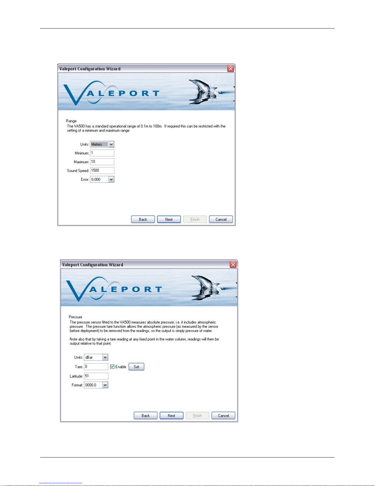
2.1 ACOUSTIC
State of the art signal processing technology provides stable, repeatable readings while
allowing the range to be extended to unrivalled distances for a 500kHz altimeter.
Type: 500 kHz broadband transducer
Range: 0.1m –100m
Resolution: 1mm
Beam Angle: ±3
2.2 PRESSURE
The optional pressure sensor fitted to the Altimeter is a temperature compensated piezo-
resistive sensor, which delivers the performance previously only available from a resonant
quartz sensor at a more cost-effective price.
Type: Temperature compensated piezo-resistive
Range: 10, 30, 100, 300 or 600 Bar
Accuracy: ±0.01% FS
Resolution: 0.001% FS
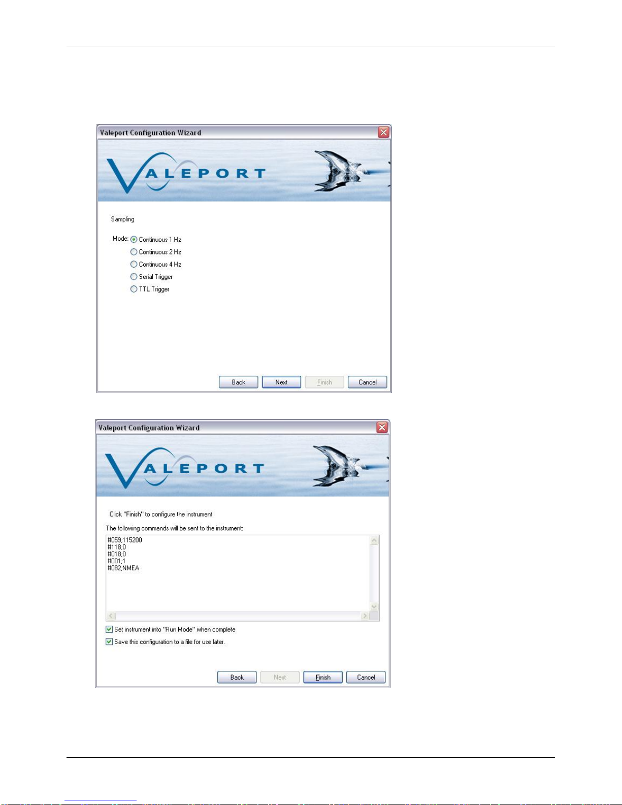
2.3 DATA ACQUISITION
Sampling: Continuous or data on demand (by serial command/TTL trigger).
Data Rate: 1, 2, 4 Hz
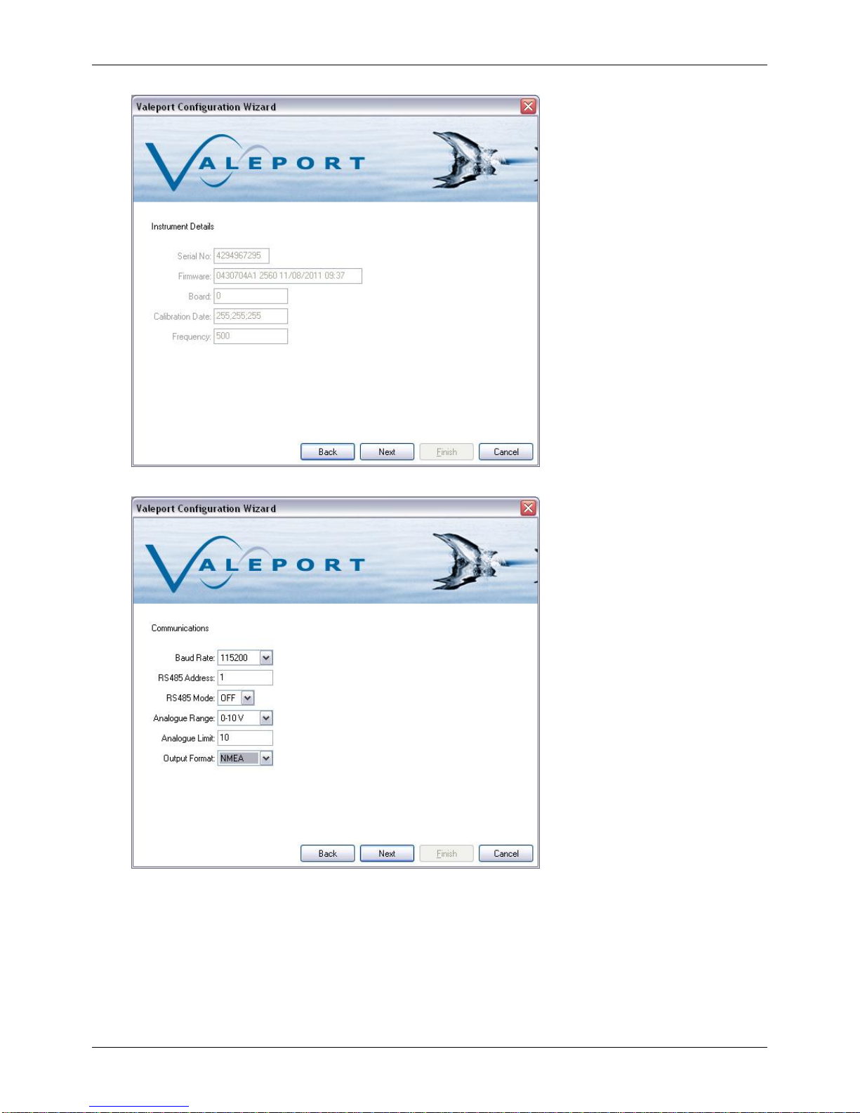
2.4 COMMUNICATIONS
RS485 is enabled by grounding a pin in the communications lead, See section 6
Digital Output: RS232 & RS485 fitted as standard
Protocol: 4800 to 115200 baud, (8,1,N)
Formats: Valeport NMEA / Tritech / Kongsberg / $SDDBT NMEA
Analogue output: 0-5/10V fitted as standard
2.5 POWER REQUIREMENTS
Input: 9 - 28vDC (isolated power supply)
Power: <125 mA @ 12V
2.6 PHYSICAL
Housing: Titanium (6000m rated)
Size: 48mm max Ø
43mm main body Ø
215mm length (including connector)
248mm length with pressure fitted
Weight: 0.95 kg (air)/ ~0.7 kg (in water)
Connector: Subconn MCBH10F (titanium)