4
USING THE UNIT
FIREPLACE SWITCH
A switch with timer functions can be connected to the unit. The switch stops the
extract air fan when the fireplace is being used. NOTE! Starting up the extract
air fan can reduce the draw of the fireplace! In winter, this can disturb the winter
mode of the ventilation unit. The situation will return to normal soon after the
fireplace mode is turned o.
ADJUSTING THE SUPPLY AND EXTRACT AIR
RATIO
This function might be needed when the air flows are adjusted at the valves
during installation. The user does not need to adjust this function once
the valves have been adjusted, and indeed should not adjust it at all. A
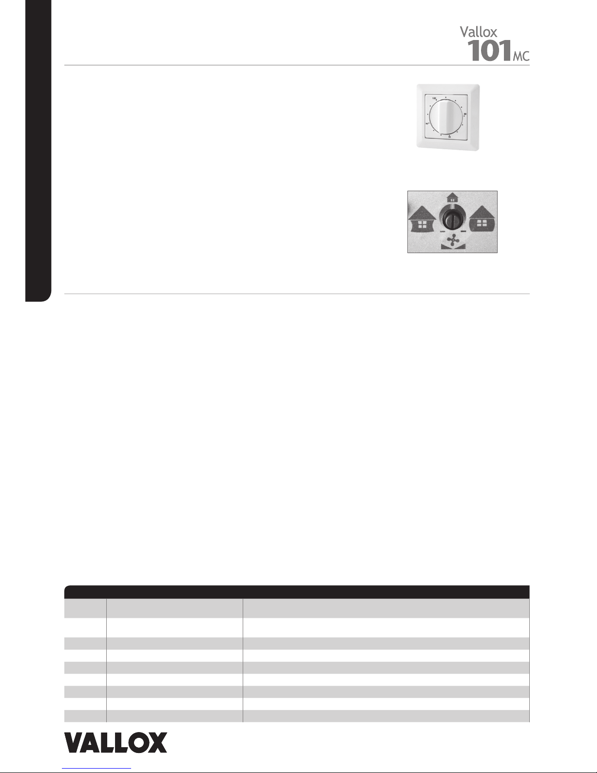
potentiometer can be used to reduce the supply or extract air flow as required.
When the potentiometer is set roughly in the centre position, neither the supply
nor the extract air flow has been reduced. When the potentiometer is turned
anti-clockwise, the supply air flow is reduced, and when the potentiometer is
turned clockwise, the extract air flow is reduced.
The potentiometer for adjusting
the supply and extract air flows
TROUBLESHOOTING
Flashing
LED
Problem Correction
1 NTC sensor of the supply air from the cell
is faulty
Check the sensor and the wires, replace as required
2 NTC sensor of the extract air is faulty Check the sensor and the wires, replace as required
3 NTC sensor of the extract air is faulty Check the sensor and the wires, replace as required
4 NTC sensor of the exhaust air is faulty Check the sensor and the wires, replace as required
5 NTC sensor of the outdoor air is faulty Check the sensor and the wires, replace as required
6 The supply air fan has stopped. Check the wiring of the fan, re¸place the fan as required
7 The extract air fan has stopped. Check the wiring of the fan, replace the fan as required
8 EEPROM is faulty Replace the circuit board
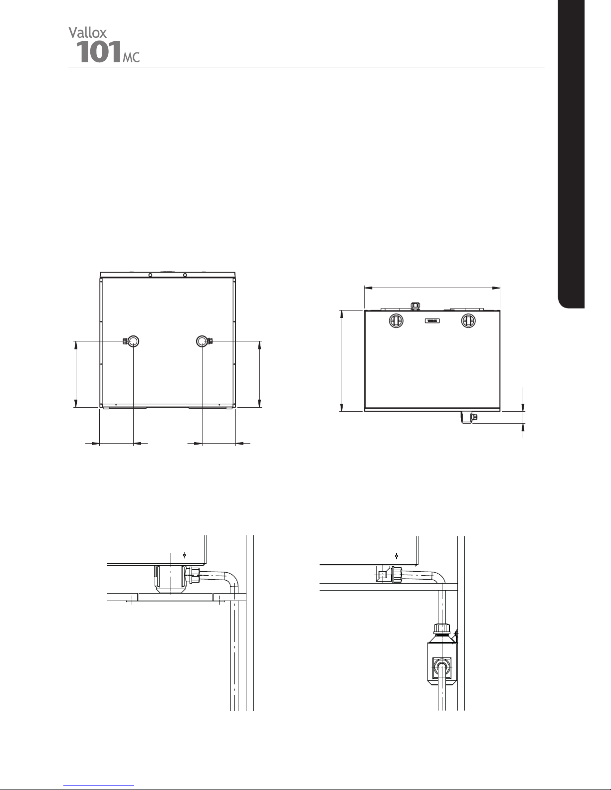
Concealed installation of
the fireplace switch (optional)
TROUBLESHOOTING TABLE
If the ventilation unit is aected by any of the errors listed in the table, the unit will report the error through the error relay,
signal light, and circuit board LEDS. The number of flashes indicates the nature of the error.
The error relay can be connected to remote monitoring.
NOTE! When remote monitoring is used, the signal light of the control panel cannot be turned on.
MAINTENANCE REMINDER
If a signal light is connected to the connectors of the unit’s error relay, the unit will send a reminder of service need every
six months,. If connected, the signal light will flash every second. Sounds made by the relay can then be heard from
inside the unit. The maintenance reminder will be set o automatically when the door of the ventilation unit is opened or
the power is turned o. The maintenance reminder can also be set o manually.
The Vallox Simple Control control panel, and the
Vallox X-Line PTXP MC and PTXPA MC control
hoods, VAK 0-10 VDC:
• The low speed is turned on, then higher-lower-higher
- Low speed under 4 V
- High speed over 6 V
- The selected speed will always be turned
on for 1-5 seconds
Vallox Capto PTC EC control hood:
• The damper is closed, then open-closed-open
• Press at a 1-5 second interval.
The service reminder will only be set o if it has been activated. Refer to the maintenance instructions for the necessary
maintenance measures.