Vallox Vallox TSK Multi 80 MV User manual

Manual
Model
Vallox TSK Multi 50 MV
Vallox TSK Multi 50 MV EH
Vallox TSK Multi 80 MV
Vallox TSK Multi 80 MV EH
Vallox TSK Multi 80 MV EHX
Vallox 90 MV
Vallox 90K MV
Vallox 096 MV
Vallox 101 MV
Vallox 110 MV
Vallox 145 MV
Vallox 245 MV
Vallox 245 MV VKL
MANUAL
Document
D3768
Valid from
3.2.2015
Updated
9.1.2018
Ventilation units

INTRODUCTION 4
Safety 4
Installation 4
Guarantee 4
Intended use 4
Disposal of the ventilation unit 4
Safety signs used in the instructions 5
Dierences between the models 5
Main parts 6
Vallox TSK Multi 50 MV and Vallox TSK Multi 80 MV 6
Vallox 90 MV 7
Vallox 90K MV 8
Vallox 096 MV, Vallox 110 MV, and Vallox 145 MV 9
Vallox 101 MV 10
Vallox 245 MV 11
Ventilation unit control 12
Connecting the ventilation unit to the cloud service 12
Ventilation unit control options 12
Unit software 15
Starting the unit 15
Turning the unit o 15
Starting up and shutting down the unit 15
SETUP WIZARD 16
Basic settings 16
Setup wizard 16
Select the language 16
Set the time 16
Set the 24- or 12-hour clock 16
Set the automatic daylight saving time 16
Set the date 17
Completing the setup 17
Expert settings 18
Lock code and access rights 18
User level 18
Parental controls 18
Basic fan settings 19
Adjusting the supply and extract air flows 19
Expert settings 20
Profile settings 20
At home and Away profiles 20
Boost profile 20
Fireplace profile 21
Finishing the setup 21
Four ventilation unit profiles 22
USING THE UNIT 22
At home 22
Away 22
Boost 22
Fireplace profile 22
Symbols for ventilation profiles 22
Changing the profile 23
Browsing the information of the At home, Away, and Boost
profiles. 23
Viewing the Fireplace profile information 24
Modifying and saving the profile settings 24
Modifying profile settings 24
Timer functions of the Boost and Fireplace profiles 24
Viewing temperature data 25
Viewing temperature statistics 25
Relative humidity of air and carbon dioxide level statistics 26
Viewing the relative humidity of air and carbon dioxide
levels measured by the sensors 26
Filter settings 27
Setting the date the filters were last replaced 27
Setting the Filter replacement reminder interval 27
Filter maintenance reminder 28
Display settings 28
Setting the sleep time 28
Adjusting the display brightness 28
Selecting the user interface language 28
Time and date 29
Setting the time and date 29
Setting the time 29
Selecting the 24- or 12-hour clock 29
Automatic daylight saving time 29
Setting the date 30
Week clock 30
Turning the week clock on 30
Setting and editing the weekly program 31
Turning the Week clock o 31
Removing the week clock settings 31
Example of setting a weekly program 32
Turning the unit o 32
Troubleshooting 33
Condensing water (User) 33
MAINTENANCE 34
Vallox TSK Multi 50 MV ja Vallox TSK Multi 80 MV 34
Before beginning maintenance work 34
Replacing the filters (User) 34
Cleaning the heat recovery cell (User) 35
Cleaning the fans (Installer) 36
Cleaning the supply air fan 36
Cleaning the extract air fan 37
CONTENTS
NOTE
You can register your Vallox MV ventilation unit with the MyVallox Cloud cloud service and sign
in into your MyVallox Cloud account at www.myvallox.com.
INTRODUCTION

© Vallox Oy - All rights reserved
CONTENTS
Vallox 90 MV 38
Before beginning maintenance work 38
Replacing the filters (User) 38
Cleaning the heat recovery cell (User) 39
Cleaning the fans (Installer) 40
Vallox 90K MV 41
Before beginning maintenance work 41
Replacing the filters (User) 41
Cleaning the heat recovery cell (User) 41
Cleaning the fans (Installer) 41
Cleaning the grease filter of the cooker hood (User) 41
Replacing the cooker hood lamp (User) 41
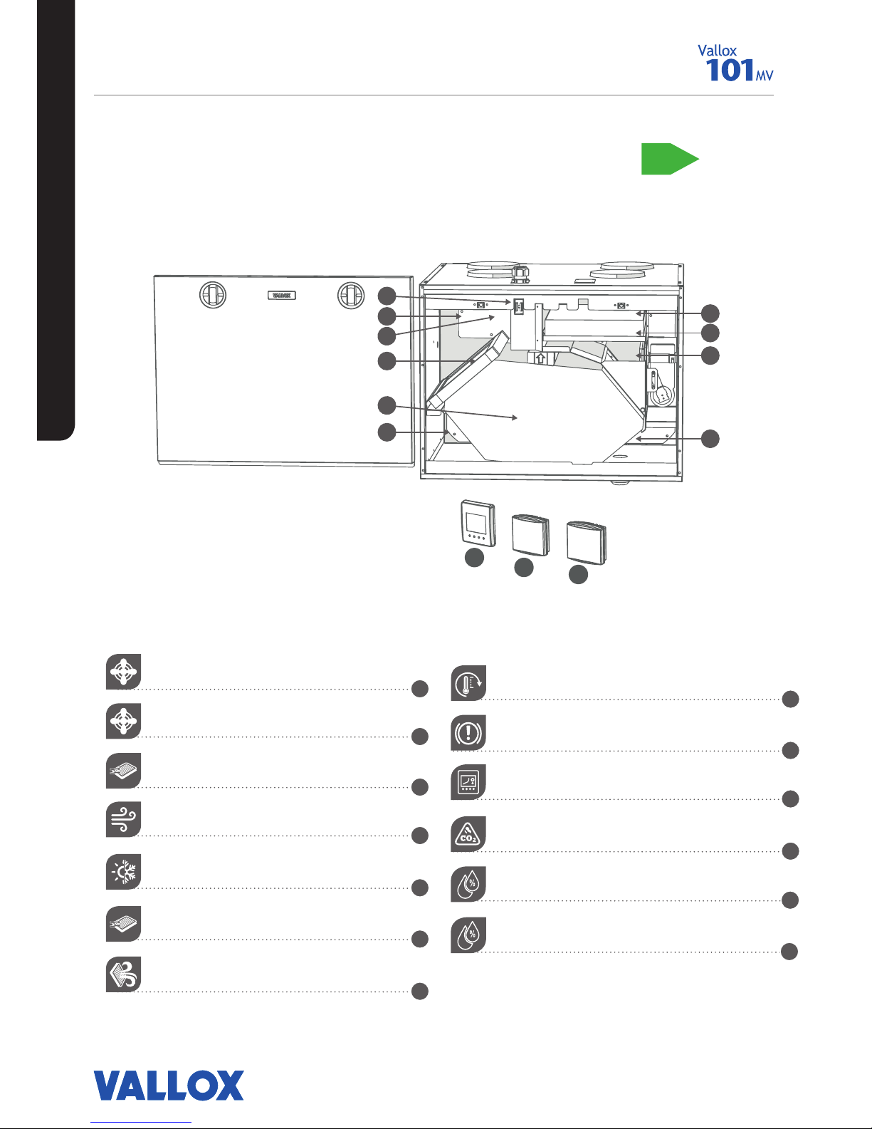
Vallox 101 MV 42
Before beginning maintenance work 42
Replacing the filters (User) 42
Cleaning the heat recovery cell (User) 43
Cleaning the fans (Installer) 44
Vallox 096 MV, Vallox 110 MV ja Vallox 145 MV 45
Before beginning maintenance work 45
Replacing the filters (User) 45
Cleaning the heat recovery cell (User) 46
Cleaning the fans (Installer) 47
Cleaning the supply air fan 47
Cleaning the extract air fan 49
Vallox 245 MV 50
Before beginning maintenance work 50
Replacing the filters (User) 50
Cleaning the heat recovery cells (User) 51
Cleaning the fans (Installer) 52
Removing and cleaning the supply and extract air fans 52
Removing the resistor 53
INSTALLATION 54
Installation site 54
Condensing water 54
Vallox TSK Multi 50 MV ja Vallox TSK Multi 80 MV 55
Installation site 55
Dimensions and duct outlets 56
Vallox 90 MV 57
Mounting on the wall 57
Mounting on the ceiling 57
Mounting the ceiling mounting plate 57
Installing the ventilation unit to the ceiling mounting plate 58
Attic floor penetration plate 58
Measuring tubes 58
Dimensioning of and space required for installation of
the Vallox Silent Klick water seal 58
Vallox 90K MV 59
Mounting on the wall 59
Installing the cooker hood 59
Measuring tubes 59
Water seal 59
Vallox 096 MV, Vallox 110 MV, Vallox 145 MV 60
Mounting on the wall 60
Mounting on the ceiling 60
Mounting the ceiling mounting plate 60
Installing the ventilation unit to the ceiling mounting plate 61
Attic floor penetration plate 61
Vallox 101 MV 62
Mounting on the ceiling 62
Mounting the ceiling mounting plate 62
Installing the ventilation unit to the ceiling mounting plate 62
Attic floor penetration plate 63
Mounting on a base (Vallox 145 MV) 64
Measuring tubes 64
Water seal 65
Dimensioning figure and space required for installation of
the Vallox Silent Klick water seal 65
Space required by the alternative Vallox Silent Klick water seal
installation method (elbow) 65
Vallox 245 MV 66
Mounting on the floor 66
Measuring tubes 66
Installing the water seals 66
TECHNICAL DATA 67
Vallox TSK Multi 50 MV ja Vallox TSK Multi 80 MV 67
Vallox 90 MV ja Vallox 90K MV 71
Vallox 096 MV 73
Vallox 101 MV 74
Vallox 110 MV 76
Vallox 145 MV 78
Vallox 245 MV 80
Vallox 245 MV VKL 83
Internal electrical connection 84
TSK Multi 50 MV ja 80 MV 84
TSK 90 MV 85
Vallox 90K MV 86
Vallox 096 MV ja Vallox 101 MV 87
Vallox 110 MV, Vallox 145 MV, Vallox 245 MV 88
Vallox 245 MV VKL 89
External electrical connection 90
Duct radiator operation chart 91
Operation and sample connection 91
Exploded view and parts list 93
Vallox TSK Multi 50 MV ja Vallox TSK Multi 80 MV 93
Vallox 90 MV 94
Vallox 90K MV 95
Vallox 096 MV 96
Vallox 101 MV 97
Vallox 110 MV 98
Vallox 145 MV 99
Vallox 245 MV 100
User level diagrams 101
Conformity certificates 102
INTRODUCTION

4
NOTE
For further information,
go to www.vallox.com
INTRODUCTION
SAFETY
Safe and appropriate handling requires knowledge of the basic
safety regulations, and of the intended use of the ventilation
system. Read this manual before operating the ventilation unit.
Retain the manual for later reference. If you lose the manual, it can
be downloaded from our website.
This user manual contains all the information necessary for safe
operation of the system. All persons who operate and maintain
the ventilation system must follow the instructions provided in this
manual. Furthermore, all local accident prevention regulations must
be observed.
Installation
Installation and setup should be carried out only by qualified
experts. Electrical installations and connections must be carried
out only by an electrician and in compliance with local regulations.
GUARANTEE
The guarantee and liability exclude damage resulting from:
• Inappropriate use of the ventilation system or the control unit
• Incorrect or inappropriate installation, setup or use
• Neglect of instructions concerning transportation, installation,
use, or maintenance
• Structural or electronic modifications or changes made to the
software
INTENDED USE
All Vallox ventilation units have been designed to provide
appropriate and continuous ventilation so as to present no threat to
health and to maintain structures in good condition.
IMPORTANT
In order to ensure that the indoor air presents no harm to
health and remains optimal also for the structures of the
building, ventilation must be kept on without disruptions. It
is recommended that ventilation be left turned on during long
holidays also. This keeps the indoor air fresh and prevents humidity
from condensing in the ventilation ducts and structures. It also
reduces the risk of moisture damage.
DISPOSAL OF THE VENTILATION UNIT
Do not dispose of electronic devices with household waste. Follow
local laws and regulations on safe and ecological disposal of the
product.
WARNING
The unit is not intended for
use by children under 8 or by
persons with reduced sensory,
physical or mental capabilities,
or whose lack of knowledge
and experience do not ensure
safe operation of the unit.
Such persons can use the
unit under supervision, or by
following the instructions of
someone who is responsible for
their safety.

5
© Vallox Oy - All rights reserved
INTRODUCTION
SAFETY SIGNS USED IN THE INSTRUCTIONS
MODELS TYPE
Vallox TSK Multi 50 MV
Vallox TSK Multi 50 MV EH
Vallox TSK Multi 80 MV
Vallox TSK Multi 80 MV EH
Vallox TSK Multi 80 MV EHX
3609-1
3609
3608-1
3608
3609-1
3608-2
(EH = post-heating)
(EHX= post-heating and additional heating)
Vallox 90 MV
Vallox 90 KMV
3527
3528
Vallox 096 MV
Vallox 101 MV
Vallox 110 MV
Vallox 145 MV
3722
3741
3702
3712
Vallox 245 MV
Vallox 245 MV VKL
3732
3732
DANGER
Indicates a hazard that will result in
death or serious injury if not avoided.
WARNING
Indicates a hazard that can result in
death or serious injury if not avoided.
CAUTION
Indicates a hazard that can result
in minor or moderate injury if not
avoided.
IMPORTANT
Indicates a hazard that can result in
damage to property or loss of data if
not avoided.
DIFFERENCES BETWEEN THE MODELS
• Power
• Size and weight
• Vallox 90 MV, Vallox 90K MV, Vallox 096 MV, and Vallox 101 do not have an additional heater. Vallox 110 MV and
Vallox 145 MV have an additional heater.
• Vallox 245 MV has an electric 1500W post-heating radiator and an electric 1500W additional heating radiator.
Vallox 245 MV VKL has a water circulation post-heating radiator and two electric 1500W additional heating
radiators.
• In Vallox 096 MV, there is a sealing tape at the bottom of the heat recovery cell. In other models, there is a
separate sealing bar under the heat recovery cell.
• Vallox 90K MV has a cooker hood underneath the unit, with a suction hole at the bottom of the unit and in the
insulation.
NOTE
The standard equipment and available accessories vary from country to country.
MOUNTING OPTIONS:
• Vallox 90 MV, Vallox 096 MV, Vallox 101 MV and Vallox 110 MV can be mounted either on the wall, or on the
ceiling by using a mounting plate (optional).
• Vallox 90K MV can only be mounted on the wall.
• Vallox 145 MV can be mounted either on the wall, or on the floor by using a floor rack (optional).
• Vallox 245 MV must always be installed on the floor by using a floor rack.
• Vallox TSK Multi 50 MV and Vallox TSK Multi 80 MV are designed to be mounted above a false ceiling.
UNIT TYPE CODES
NOTE
Indicates essential
information about the
product.
TIP
Provides additional
information about the use of
the product and its benefits.

MAIN PARTS
P
O
I
S
T
O
I
L
M
A
N
L
Ä
M
M
Ö
N
T
A
L
T
E
E
N
O
T
O
N
V
U
O
S
I
H
Y
Ö
T
Y
S
U
H
D
E
L
U
O
K
K
A
A+
8
9
10
11
12
1
2
3
4
5
6
7
6
Supply air fan
Extract air fan
Post-heating radiator
Heat recovery cell
Supply air filter F7
Supply air filter G4
Extract air filter G4
R model in the figure
Bypass flap
Safety switch
Control panel
Carbon dioxide sensor
Humidity sensor
10
11
12
58
9
3
17
2
6
4
INTRODUCTION
VALLOX TSK MULTI 50 MV AND
VALLOX TSK MULTI 80 MV

7
© Vallox Oy - All rights reserved
5
10
11
12
8
9
3 1
7
2
6
4
Extract air fan
Supply air fan
Supply air filter F7
Heat recovery cell
Automatic summer/winter damper
Supply air filter G4
Extract air filter G4
Post-heating radiator
Safety switch
Control panel
Carbon dioxide sensor
Humidity sensor
B
8
9
10
11
12
1
2
3
4
5
6
7
R model in the
figure
MAIN PARTS
INTRODUCTION
VALLOX 90 MV

8
INTRODUCTION
VALLOX 90K MV
Extract air fan
Supply air fan
Supply air filter F7
Heat recovery cell
Automatic summer/winter damper
Supply air filter G4
Extract air filter G4
Post-heating radiator
Safety switch
Control panel
Carbon dioxide sensor
Humidity sensor
Cooker hood
Cooker hood damper adjustment
Fan speed adjustment
B
MAIN PARTS
5
10
11
12
8
9
3 1
7
2
6
4
13
14 15
8
9
10
11
12
1
2
3
4
5
6
7
13
14
15
R model in the
figure

9
© Vallox Oy - All rights reserved
9
© Vallox Oy - All rights reserved
VALLOX 096 MV, VALLOX 110 MV, AND VALLOX 145
MV
R model in the
figure
Extract air fan (behind the protective cover)
Supply air fan (behind the extract air duct)
Supply air filter F7
Heat recovery cell
Bypass flap
Supply air filter G4
Extract air filter G4
P
O
I
S
T
O
I
L
M
A
N
L
Ä
M
M
Ö
N
T
A
L
T
E
E
N
O
T
O
N
V
U
O
S
I
H
Y
Ö
T
Y
S
U
H
D
E
L
U
O
K
K
A
A+
MAIN PARTS
INTRODUCTION
Post-heating radiator (behind the extract air duct)
Safety switch
Control panel
Carbon dioxide sensor
Humidity sensor
Internal humidity sensor
8
9
10
11
12
1
2
3
4
5
6
7
13

10
INTRODUCTION
1
5
3
6
8
9
13
7
2
4
12
11
10
VALLOX 101 MV
R model in the
figure
Extract air fan
Supply air fan
Supply air filter F7
Heat recovery cell
Bypass flap
Supply air filter G4
Extract air filter G4
P
O
I
S
T
O
I
L
M
A
N
L
Ä
M
M
Ö
N
T
A
L
T
E
E
N
O
T
O
N
V
U
O
S
I
H
Y
Ö
T
Y
S
U
H
D
E
L
U
O
K
K
A
A+
MAIN PARTS
Post-heating radiator (in the supply air duct)
Safety switch
Control panel
Carbon dioxide sensor
Humidity sensor
Internal humidity sensor
8
9
10
11
12
1
2
3
4
5
6
7
13

11
© Vallox Oy - All rights reserved
INTRODUCTION
R model in the
figure
Supply air fan
Extract air fan
Supply air filter F7
Heat recovery cell, 2 pcs
Bypass flap
Supply air filter G4
Extract air filter G4
Post-heating radiator
5
1
4
87
9
4
3
5
14
1
4
87
9
4
3
2
6
13
10 11 12
Safety switch
Control panel
Carbon dioxide sensor
Humidity sensor
Internal humidity sensor (behind the electric box)
Post-heating liquid radiator
8
9
10
11
12
1
2
3
4
5
6
7
13
14
VALLOX 245 MV

12
INTRODUCTION
TIP
The MyVallox Control control
panel automatically switches to
the sleep mode when the Sleep
time set in the Display settings
has elapsed. You can wake up
the control panel by pressing
any control panel button.
VENTILATION UNIT CONTROL
Connecting the ventilation unit to the
cloud service
The ventilation unit can be connected to the MyVallox
Cloud cloud service. The cloud service allows for controlling
ventilation remotely also, using e.g. a smartphone or tablet.
Also the unit software is updated automatically through
the cloud service. To connect to the cloud service, the
ventilation unit must be connected to the Internet via LAN
and registered with the cloud service. At the same time you
create a MyVallox Cloud account for yourself. Read more
about the service at www.myvallox.com.
Ventilation unit control options
Operation of the Vallox ventilation unit can be controlled by
the following means:
• Through the control panel installed in the building
• Through the MyVallox Home local area network
connection and the MyVallox Home/Cloud user interface.
• Through the MyVallox Cloud cloud service and the
MyVallox Home/Cloud user interface.
• Through a remote monitoring service or building
automation that uses voltage signals or Modbus
messages
In addition to the integrated humidity sensor, ventilation
can also be adjusted automatically using the optional
carbon dioxide and humidity sensors. When these are
used, ventilation remains optimal even when the dwelling is
unoccupied.
Each user can use the week clock to adjust the ventilation to
fit their individual lifestyle.

13
© Vallox Oy - All rights reserved
INTRODUCTION
SYSTEM DESCRIPTION
Modbus
1
4
2
3
5
6
MyVallox Cloud
Vallox MV
MyVallox Control
1. Internet
2. WLAN
3. Router
4. WLAN/LAN
5. Additional switch
6. Sensors
VENTILATION UNIT CONTROL

14
VENTILATION UNIT CONTROL
The Change profile button changes the ventilation profile or
the operating status used.
The Profile information button allows you to view the
currently active profile information.
The Temperature button displays temperature and sensor
information.
The Settings button opens the settings.
The Back button takes you backwards in the menu.
The Left arrow button takes you leftward in the menu.
The Right arrow button takes you rightward in the menu.
The OK button accepts the selected option.
The Select button selects an option from the list.
The Edit button allows you to edit settings.
The Plus button allows you to:
• Increase the value of the selected setting.
• Move to the next menu item.
• Move from a one-day view to a week view in the
temperature, relative humidity of air and carbon dioxide
level graphs.
The Minus button allows you to:
• Reduce the value of the selected setting.
• Return to the previous menu item.
• Move from a week view to a one-day view in the
temperature, relative humidity of air and carbon dioxide
level graphs.
The Up arrow button takes you upward in the menu.
The Down arrow button takes you downwards in the menu.
The Statistics button opens the temperature, relative
humidity of air and carbon dioxide level graphs (1 day or 1
week).
These icons indicate the hierarchy level of the settings.
This icon indicates when the feature is turned o at your user
level.
BUTTON DESCRIPTION
NOTE
The MyVallox Control control
panel contains the buttons
described in the following table.
You can press the graphical user
interface buttons by using the
ring-shaped buttons below the
control panel. The control panel
does not have a touch screen.
CONTROL PANEL BUTTONS
INTRODUCTION

15
© Vallox Oy - All rights reserved
INTRODUCTION
STARTING UP AND SHUTTING DOWN THE UNIT
Unit software
We recommend that the latest software version be always
used. Check and download the latest version at
http://www.vallox.com or at cloud.vallox.com either before or
immediately after startup.
The current software version of the ventilation unit is shown
on the control panel display when the unit is connected to
the mains or factory settings are restored. Alternatively, the
current software version can be checked from the Diagnostics
display of the Maintenance menu.
Download the software into the unit using the USB Micro-B
port of the control panel.
Starting the unit
If you are starting the ventilation unit for the first time or after
a maintenance procedure, first connect it to the mains. This
will start the unit. During start-up, the diagnostics display
appears for a few seconds. Once the download is complete,
a profile display opens showing the latest saved status of the
unit.
If the ventilation unit was turned o from the control panel
(see Turning the unit o), you can start it by pressing any
control panel button.
Turning the unit o
To turn the ventilation unit o:
1. Select Turn unit o using the arrow buttons.
2. Select OK.
3. Press OK to confirm the selection. The ventilation unit
has now been turned off.
IMPORTANT
It is recommended that the ventilation be kept turned on
without disruptions.
NOTE
The first starting of the unit may
take a while, because of the
software version check.

16
SETUP WIZARD
BASIC SETTINGS
SETUP WIZARD
SETUP WIZARD
The following settings will be configured during the setup of the
ventilation system:
• user interface language
• time and date
• system administrator lock code
• parental controls, if turned on
• fan settings
• user profile settings, such as the temperature.
The qualified ventilation installer must complete the fan settings in
accordance with the ventilation plan. Do not change these settings.
1. Start the Vallox ventilation unit.
2. When the unit is started for the first time, the language menu
opens on the control panel display. Select OK.
3. The setup wizard is launched.
Select the language
1. Use the arrow buttons to select the language.
2. Select OK.
3. The language has now been set, and the control panel will
move on to the time settings.
Set the time
1. Use the Plus and Minus buttons to set the hours.
2. Select Right arrow.
3. Use the Plus and Minus buttons to set the minutes.
4. The time is now set.
5. Proceed to the next phase by selecting Right arrow.
Set the 24- or 12-hour clock
The 24-hour clock is used by default.
To use the 12-hour clock:
1. Select Minus. The 24-Hour time setting value is changed to O.
2. Proceed to the next phase by selecting Right arrow.
Set the automatic daylight saving time
By default, the automatic daylight saving time is on.
To use the manual daylight saving time setting:
1. Select Minus. The Dayl.saving time setting value is changed to O.
2. The manual daylight saving time setting is now on.
3. Proceed to the next phase by selecting Right arrow.

17
© Vallox Oy - All rights reserved
SETUP WIZARD
Set the date
1. Use the Plus and Minus buttons to set the date.
2. Select Right arrow.
3. Use the Plus and Minus buttons to set the month.
4. Select Right arrow.
5. Use the Plus and Minus buttons to set the year.
6. Select OK.
7. The date is now set.
TIP
You can browse the Time and date settings by using the
Right arrow button.
Completing the setup
Once you have completed the basic settings for the setup,
select OK to proceed to the expert settings of the ventilation
unit.
Select Back to use the ventilation unit on factory settings
and complete the configuration of the expert settings later.
NOTE
Expert settings are settings that use e.g. airflow
measurement equipment.
BASIC SETTINGS

18
EXPERT SETTINGS
Lock code and access rights
NOTE
The default lock code is 0000, i.e. the lock code inquiry is
turned o.
1. Enter the first digit of the lock code using the Up arrow and
Down arrow buttons. Proceed to the next digit by selecting
Right arrow.
2. Set the remaining digits of the lock code in the same way.
3. Select OK.
4. The lock code is now set.
User level
There are three user levels:
• Extensive - At the extensive user level, users can access all
ventilation unit settings.
• Normal - At the normal user level, access to some menus is
restricted.
• Limited - At the limited user level, users have access only to
the basic functions of the ventilation unit.
For more information on user levels, see Chapter “User level
diagrams”.
1. Use the Plus and Minus buttons to set the user level.
2. The user level is now set.
3. Proceed to the next phase by selecting Right arrow.
Parental controls
Parental controls lock the control panel so that no damage
can be done to the ventilation unit by random pressing of the
control panel buttons.
1. By default, the parental controls are turned off. Use the Plus
and Minus buttons to turn the parental controls on.
2. Select OK.
3. The parental controls are now set.
TIP
You can browse the Lock code and access rights settings with
the Right arrow button.
NOTE
The access code of the parental controls cannot be changed.
The access code is always 1001.
Parental controls access code:
1 0 0 1
Enter the new access code
here:
SETUP WIZARD

19
© Vallox Oy - All rights reserved
SETUP WIZARD
EXPERT SETTINGS
Basic fan settings
IMPORTANT
Adjust the air flows according to the values specified in the
ventilation plan. It is recommended that the air flows be
adjusted without having to choke the air flows at the valves.
This is the most energy-ecient set up.
First, set both values as close to the ideal value as possible
by looking at the supply and extract air fan curves. If the
ratio between the air flows is very high at first, the ventilation
unit may have to carry out extra defrosting cycles in sub-zero
temperatures, thus making adjustment of the air flows more
complicated. Check the air flows by measuring them at the
valves, and fine-tune the percentage values as required.
NOTE
If the outside air is extremely cold (below -10°C on an
aluminium cell or below -3°C on a plastic cell), the ventilation
unit may have to defrost the heat recovery cell. If this
happens, the Defrosting icon will be displayed on the control
panel. The air flows cannot be adjusted during defrosting.
Adjusting the supply and extract air flows
1. Use the Plus and Minus buttons to set the supply air fan
ratio as a percentage of the maximum output ratio. The
fan speed (1/min) will change accordingly.
2. Measure and adjust the supply air flows from the valves.
3. Press the Right arrow button.
4. Use the Plus and Minus buttons to set the extract air fan
ratio as a percentage of the maximum output ratio. The
fan speed (1/min) will change accordingly. Measure and
adjust the extract air flows from the valves.
5. Select OK. Supply and extract air flow settings are now
complete.
6. Record the set percentages in the measurement log.
Do not change the output ratio between the supply and
extract air fans once the settings are complete. The same
ratio is also used in the Away and Boost profiles.
TIP
You can browse the Basic fan settings by using the Right
arrow button.
NOTE
If the use of the ventilation unit has been started before air
flow adjustment, we recommend that the factory settings of
the ventilation unit be restored before adjustment is started
(see “Save and restore settings”). This ensure that the unit
settings are optimal for adjusting the air flows and that any
settings made during the adjustment are saved as setup
settings. Any later changes will be saved as user settings.
Both the setup and user settings can be restored later even
if the settings had been modified later.
IMPORTANT
The supply and extract air
settings have been completed
by a specialist during setup
of the ventilation unit. These
settings should be changed
only when the ventilation
unit is reconfigured, and not
at any other time. Changing
the ventilation settings so
that overpressure is created
can result in damage to the
structures of the building.

20
SETUP WIZARD
PROFILE SETTINGS
NOTE
By default, the At home profile uses the higher basic ventilation
fan speed. We recommend that this basic ventilation setting be
used with the At home profile. Once you have set the fan speed
for the At home profile, the fan speed for the Away profile will
by default be set to -30% of the At home profile fan speed.
We recommend that the default fan speed settings be used.
However, the settings can be changed as required.
At home and Away profiles
To set the ventilation settings of the profiles:
1. Use the Plus or Minus buttons to set the profile fan speed
as a percentage of the maximum output ratio.
2. The fan speed is now set for the profile.
3. Proceed to the next phase by selecting Right arrow.
4. Use the Plus or Minus buttons to set the desired supply air
temperature for the profile. You can adjust the temperature
in the range +10°C ... +25°C.
5. The profile supply air temperature is now set.
6. Proceed to the next phase by selecting Right arrow.
7. Use the Plus and Minus buttons to turn the automatic fan
speed control based on relative humidity of air on or off.
8. The automatic fan speed control, based on the relative
humidity of air, is now set.
9. Proceed to the next phase by selecting Right arrow.
10. Use the Plus and Minus buttons to turn the automatic fan
speed control based on carbon dioxide content on or off.
11. The automatic fan speed control, based on the carbon
dioxide level, is now set.
12. Select OK.
13. Proceed to the settings of the next profile by selecting Right
arrow.
NOTE
Once you have set the fan speed for the At home profile, the
fan speed for the Boost profile will by default be set to +30%
of the At home profile fan speed. It is recommended that this
fan speed setting be used for the Boost profile. However, the
setting can be changed as required.
Boost profile
The fan speed, supply air temperature, and the automatic fan
speed control (based on either relative humidity of air or carbon
dioxide level) is set for the Boost profile in the same way as for
the At home and Away profiles. The Boost profile also has a
timer setting.
TIP
You can browse the At home
profile settings with the Right
arrow button.
EXPERT SETTINGS
This manual suits for next models
12
Table of contents
Other Vallox Ventilation manuals