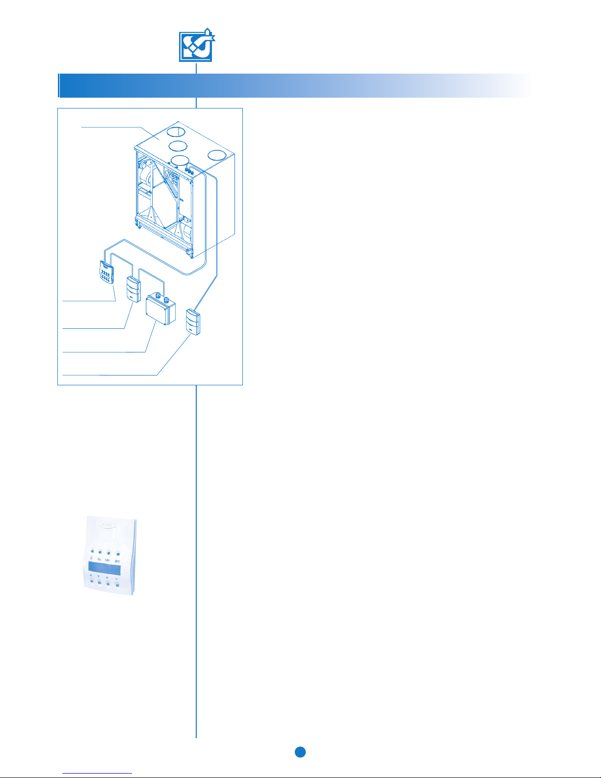
Vallox 180SE Specification sheet

DIGIT SED
ELECTRONIC CONTROLLER
WITH LCD DISPLAY
• 1.09.283E
• 19.8.2008
• Tyyppi 3486
© VALLOX
INSTRUCTIONS FOR USE AND MAINTENANCE
Electronically controlled
supply / extract ventilation
with heat recovery
© VALLOX • We reserve the right to make changes without prior notification.
SE

VALLOX 180 has been initially adjusted for
normal circumstances in your home. Ventilation
adjustment is needed mainly in the following
circumstances:
VALLOX 180 SE
TABLE OF CONTENTS
2
2
VALLOX 180 models
Code: 3486
VALLOX 180 AC
• Equipped with AC fans
VALLOX 180 DC
• Equipped with DC fans
Letter L or R after the name of the unit indicates
whether the unit is left- or right-handed.
© VALLOX • We reserve the right to make changes without prior notification.
EVERYDAY QUICK GUIDE
NOTE!
Never switch ventilation off,
because ventilation keeps indoor air
quality uniform and removes gases
and dust emanating from the
structures.
• Taking a bath:
Boost ventilation in bathing and washing
facilities in order to ensure that the rooms
get dry as quickly as possible. It is advisab-
le to have boosted ventilation on for 2 to 3
hours after taking a sauna bath, unless au-
tomatic adjustment based on humidity con-
tent is used.
• Washing and drying clothes:
Boost ventilation in washing and drying
rooms during the activity, unless automatic
adjustment based on humidity content is
used.
• Sleeping:
Ventilation in a bedroom has to be suffi-
cient throughout the night. The level is cor-
rect when air does not smell fusty when
you enter the room in the morning. If the
carbon dioxide content of a room is moni-
tored and ventilation is adjusted according-
ly, air will always be fresh.
• Empty dwelling:
To save energy, ventilation can be adjusted
to the minimum level.
• Cooking:
If the ventilation unit is connected to a coo-
ker hood, boost ventilation during cooking.
The most common way to abate coo-
king fumes is to have a separate
cooker hood.
1. THREE QUESTIONS ABOUT VENTILATION
1.1. Why is air replaced in dwellings? ................................................. p. 3
1.2. What are the characteristics of adequate ventilation? ...................... p. 3
1.3. How much air is replaced? ........................................................... p. 3
2 INSTRUCTIONS FOR USING VALLOX 140 Effect SE
2.1. Making the unit ready for operation ............................................... p. 4
2.2. Ventilation control ........................................................................ p. 4
2.3. Ventilation control with control panel .............................................. p. 4
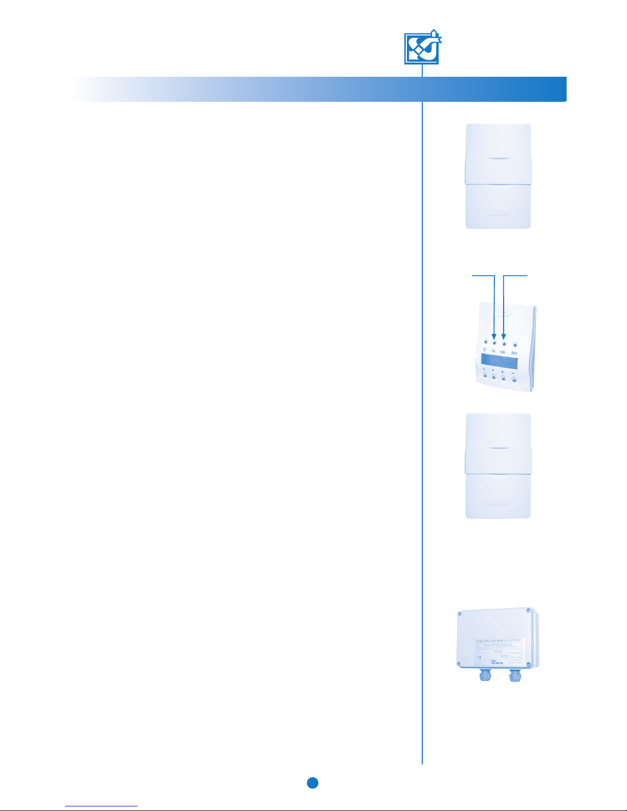
2.4. Ventilation control with carbon dioxide sensor ................................. p. 5
2.5. Ventilation control with humidity sensor .......................................... p. 5
2.6. Ventilation control with voltage or current signal .............................. p. 5
2.7. Ventilation control with remote monitoring system ............................ p. 5
2.8. Post-heating ................................................................................ p. 6
2.9. Supply air constant temperature control .......................................... p. 6
2.10. Supply air cascade control ........................................................... p. 6
2.11. Heat recovery bypass function ...................................................... p. 6
2.12. Heat recovery antifrost function ..................................................... p. 7
2.13. Antifreezing function of water-circulating post-heating unit .................. p. 7
2.14. Maintenance reminder ................................................................. p. 7
2.15. Filter guard function ..................................................................... p. 7
2.16. Fireplace switch / boosting .......................................................... p. 8
2.17. Fault signal relay ......................................................................... p. 8
2.18. Air filtering ................................................................................. p. 8
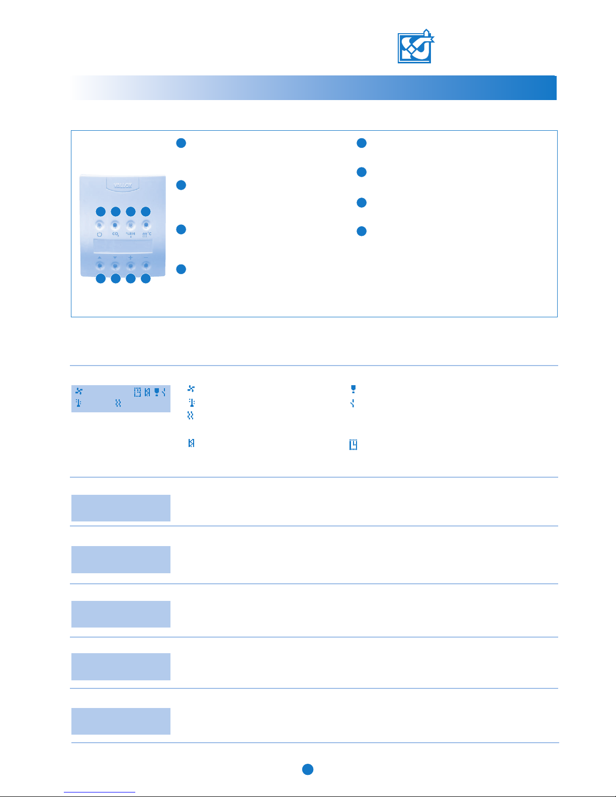
3. CONTROL PANEL
3.1. Instructions for use ....................................................................... p. 9
3.2. Operating menu .......................................................................... p. 9
3.3. Settings menu .............................................................................. p. 10
3.4. Week clock control ...................................................................... p. 12
3.5. Factory settings ........................................................................... p. 12
4. MAINTENANCE INSTRUCTIONS
4.1. Filters ......................................................................................... p. 13
4.2. Fans ........................................................................................... p. 13
4.3. Water-circulating post-heating radiator.............................................p. 14
4.4. Filter guard ................................................................................. p. 14
4.5. Condensing water ....................................................................... p. 14
5. TROUBLESHOOTING.................................................................................. p. 15

Autumn
• Wash or change the coarse filter and clean
or change the fine filter if needed.
• Check that the heat recovery cell is clean.
• Check that the condensing water outlet is
not clogged.
• Switch the post-heating radiator on.
Spring:
• Wash or change the coarse filter and clean
or change the fine filter if needed.
• Clean the fan blades and the post-heating
unit if needed.
• Check that summer ventilation is in
operation.
• Switch the post-heating radiator off.
VALLOX 180 SE
THREE QUESTIONS ABOUT VENTILATION
3© VALLOX • We reserve the right to make changes without prior notification.
SEASONAL CALENDAR
NOTE!
For further details, see inner pages.
1. THREE QUESTIONS ABOUT VENTILATION
1.1. Why is air replaced in dwellings?
Good ventilation promotes healthy living for both residents and the building. Air in a dwelling needs to
be replaced in order to remove humidity brought about by living as well as impurities
emanating from structures and human bodies. Impurities of indoor air include carbon dioxide,
formaldehyde, radon and other gases as well as dust.
Mechanical ventilation is needed in order to be able to adjust air circulation as needed by
the residents. In a tightly sealed house, air does not circulate sufficiently by natural means.
Even in a poorly sealed house air is only replaced because of differences between indoor
and outdoor air temperatures, or because of winds. This means that ventilation is dependent
on weather conditions and cannot be regulated.
It is especially important for humidity and carbon dioxide content of indoor air to stay at a
healthy level. Recommended humidity content of good indoor air is approximately 45%.
Humidity content is lower in winter and higher in summer and autumn. Dust mites thrive in
indoor air if humidity exceeds 50%, and if humidity stays at over 60% for a long time in
winter, water will condense in the cold structures of the house and mould will start to form.
The recommended maximum carbon dioxide content in good indoor air is circa 1,000 ppm.
1.2. What are the characteristics of adequate ventilation?
• Indoor air stays fresh in all the rooms of the dwelling, also in bedrooms during night.
Without adequate ventilation, carbon dioxide content tends to rise high especially in
bedrooms.
• The bathroom and the sauna get dry quickly.
• During the heating season, the windows and other outer wall structures remain dry.
• Humidity in indoor air is not condensed in the ventilation ducts.
• Air is fresh in the toilet as well.
1.3. How much air is replaced?
For air to be clean to breathe, it has to be replaced with outdoor air once in two hours.
In a new and a renovated house, air needs to be circulated continually, at least once an
hour, during the first year in order to remove harmful gases and structural humidity from the
structures. In buildings that are more than a year old and dry, ventilation can be regulated
as needed. Ventilation is boosted during for instance a sauna bath, clothes washing and
cooking, and reduced during very cold periods or when there is nobody at home. Carbon
dioxide and humidity sensors adjust ventilation in the rooms automatically as needed.

DIGIT SED
ELECTRONIC CONTROLLER
WITH LCD DISPLAY
VALLOX 180 SE
4
INSTRUCTIONS FOR USE
2. Instructions for use
For indoor air to stay healthy and beneficial also for the structures of the dwelling,
ventilation has to be in operation continually. It is not advisable to stop ventilation
even for longer holidays, because it makes indoor air stuffy. Also, during the
heating season indoor air humidity may condense in the ducts and structures
and therefore cause humidity damage. The sensors automatically adjust ventilation
to an optimal level even if the dwelling is empty.
2.1. Making the unit ready for operation
1. After VALLOX 180 has been connected permanently to the mains supply
and the control panel to the unit, it is ready for operation.
2. Turn the unit on and choose a suitable power of ventilation at the control
panel. There are either one or more control panels. See the instructions for
using the control panel in Section 3.2.1.
In normal conditions basic ventilation, with a change of air every two hours,
is sufficient in living areas. Boosting is needed during for example sauna baths,
cooking, clothes washing or family parties. If carbon dioxide and humidity
sensors have been installed in the system, VALLOX 180 also takes care of
demand controlled ventilation.
2.2. Ventilation control
The unit can be fully controlled with the control panel delivered with the unit or
with an optional LON converter.
The standard week clock control can be used to control the fan power of the
unit and the setpoint for supply air temperature.
Furthermore, demand controlled ventilation can be adjusted automatically with optional
carbon dioxide and humidity sensors.
The fan power of the unit can also be controlled with a voltage or current signal.
2.3. Ventilation control with control panel
The control panel can be used for the following ventilation control functions:
Functions for adjusting ventilation power:
• Starting and stopping.
• Power adjustment (8 positions).
• Setting the basic fan speed and the maximum fan speed. Ventilation power cannot be
set lower than the basic fan speed. When carbon dioxide and/or relative humidity
adjustments are activated, power cannot be adjusted higher than the set maximum fan
speed. When humidity and carbon dioxide adjustments are switched off, fan speed can
be raised to position 8 (factory setting). Maximum fan speed limitation can be selected
at the settings menu to be in operation permanently (see the instructions for using the
control panel, Section 3.3.3.).
Supply air temperature adjustment functions (postiheating unit is an option)
• Switching the electric or water-circulating post-heating unit on / off.
• Setting the desired supply air temperature (+10°C...+30°C).
• Selecting the method for controlling the desired supply air temperature (standard
temperature adjustment, cascade based temperature adjustment).
Preheating
• Setting the control temperature for the preheating unit (–6°C...+15°C exhaust air).
• Changing the setpoints.
• There may be three control panels at most. When two or more control panels are used,
the most recent control function is valid.
© VALLOX • We reserve the right to make changes without prior notification.
CONTROL PANEL
CO2- SENSOR (OPTION)
LON converter (option)
%RH SENSOR (OPTION)
VALLOX 180 AC/DC
(L model in the picture)

VALLOX 180 SE
INSTRUCTIONS FOR USE
5© VALLOX • We reserve the right to make changes without prior notification.
2.4. Ventilation control with carbon dioxide sensor (option)
• In carbon dioxide control, VALLOX 180 SE adjusts fan speed so as to keep carbon
dioxide content in the ventilation zone below the setpoint. When two or more sensors
are used, fan speed is adjusted according to the highest measuring result.
• It is possible to connect 1...5 carbon dioxide sensors as options to the VALLOX 180 SE
unit.
• The adjustment is switched on / off and, if needed, the setpoint (500...2000 ppm) is set
at the control panel. The factory setting is 900 ppm. The recommended maximum
carbon dioxide content in good indoor air is 1,000 ppm.
• When carbon dioxide control is on, the control panel may be used to raise fan speed to
the maximum fan speed and to decrease it to the basic fan speed. In carbon dioxide
control, maximum fan speed limitation is enabled.
2.5. Ventilation control with humidity sensor (option)
There are two methods for adjusting fan speed.
1Automatic humidity setting, which is suitable for controlling humidity in washing facilities, for
instance. The program records current humidity level and selects it as the setpoint, which
it then uses as the target for drying air in a bathroom e.g. after a shower. The setpoint
automatically varies according to season, for instance, and is always at the right level.
This setting is factory selected.
2 Humidity level can also be set fixed. The setting can be set at the control panel, within the
range of 1...99 %RH. This can be used in public saunas and swimming pools, for
instance. The program aims at keeping humidity at the setpoint. The setpoint can be
changed if needed.
Adjusting mode is chosen at the controller. Recommended humidity content of good indoor
air is approximately 45%.
• When this control is on, the control panel may be used to raise fan speed to the
maximum fan speed and to decrease it to the basic fan speed.
• In humidity control, fan speed varies between the basic and maximum fan speeds
selected.
• When the unit is first taken into use with automatic setpoint search enabled (factory setting), it
takes 3 to 10 hours for the program to define the value. During this time, humidity adjustment is
not enabled (because the first value, selected at the factory, is 100%).
• Automatic search is enabled even if humidity control is not selected.
2.6. Ventilation control with voltage or current signal
VALLOX 180 SE fan power can be controlled with a voltage or current signal coming from
remote monitoring.
• The signal can be used to select speeds 0–8. However, the set maximum fan speed
cannot be exceeded if carbon dioxide or humidity adjustment is active, or if maximum
fan speed limitation has been selected in the settings menu to be in operation all the time
(see the instructions for using the control panel in Section 3.3.6).
• The signal changes the basic fan speed.
• The signal does not lock fan speed, i.e. fan speed can be changed at the control panel
within the set limits. Carbon dioxide and humidity adjustment also operate within the set
limits.
2.7. Ventilation control with remote monitoring system (option)
• With an optional LON converter, VALLOX 180 SE can be connected to the remote
monitoring system.
• When
VALLOX 180 SE is connected to the remote monitoring system, compatibility
between the two needs to be ensured.
• The remote monitoring system can control the same functions as the control panel does.
• The remote monitoring system works in parallel with the control panel as well as carbon
dioxide and humidity sensors.
Carbon dioxide sensor (CO2)
Humidity sensor (RH)
LON converter
2.4. 2.5.

VALLOX 180 SE
6
INSTRUCTIONS FOR USE
2.8.
© VALLOX • We reserve the right to make changes without prior notification.
Remember!
Switch post-heating off when it starts
to get too warm in the dwelling becau-
se of warm weathers.
Switch post-heating on again when it
gets cooler in autumn.
2.8. Post-heating
For most of the year, heat recovered from air to be extracted is enough to warm the cold air
coming from the outside to a suitable temperature. If the heat of extract air is not enough, air
coming from the outside may be heated further, as needed, with the radiator delivered with the
unit.
The post-heating radiator may be electric or water-circulating. Heating can in both cases be
activated at the control panel (see the instructions for using the control panel in Section 3.1.).
When heating has been activated, the unit automatically adjusts the temperature selected.
2.9. Supply air constant temperature control
• VALLOX 180 SE has a relative post-heating control; when the temperature selected exceeds
supply air temperature by more than 2.5 °C, the radiator is on at 100%, and when the
temperature difference gets smaller, the period of active operation is automatically reduced in
two-minute sequences. The adjustment range for heating is 10...30 °C.
• The heating radiator is on when the ( ) sign is displayed.
• Temperature control is only active when post-heating has been switched on.
2.10. Supply air cascade control
• Supply air temperature control can be changed into cascade control.
• It changes the controlling principle of the post-heating radiator. The temperature of air blown
to the ventilation zone is controlled on the basis of extract air.
• The program tries to keep supply air temperature at a value determined by the difference
between extract air and the setpoint as follows: If extract air is warmer than the setpoint,
supply air temperature is lower than the setpoint by the difference. If extract air is colder,
supply air is higher than the setpoint by the difference.
As an example, if the temperature in the ventilation zone is 25 °C and the setpoint is 24 °C,
the aim is to blow 23 °C air to the ventilation zone. If the temperature in the ventilation zone is
24 °C and the setpoint is 25 °C, the aim is to blow 26 °C air to the ventilation zone.
• The aim is to keep the temperature of air blown to the ventilation zone always within the range
of 10...30 °C.
• Cascade control can be selected at the control panel, and it is active when post-heating has
been switched on.
• The heating radiator is on when the ( ) sign is displayed.
2.11. Heat recovery bypass function
• The bypass function tries to get as cool supply air as possible to the ventilation zone by
comparing the measuring results of the outdoor air and extract air sensors.
• The heat recovery cell is bypassed when post-heating is switched off, outdoor air temperature
is two degrees more than the setpoint and extract air is warmer than outdoor air.
• The setpoint can be changed between 0…+25 °C. (Factory setting 12 °C.)

VALLOX 180 SE
Pressure difference switch
INSTRUCTIONS FOR USE
© VALLOX • We reserve the right to make changes without prior notification.
7
2.12. Heat recovery antifrost function and preheating
• Antifrost prevents the heat recovery cell from freezing, thus ensuring proper ventilation
even in cold periods.
• Antifrost is implemented by stopping the supply air fan. The stopping function is controlled
on the basis of the measurement data given by the temperature sensor that measures the
temperature of exhaust air after the heat recovery cell.
• The supply air fan stops when exhaust air temperature falls to the setpoint (factory setting
+6 °C) and starts when exhaust air temperature has risen to the value set (hysteresis
setting, factory setting +3 °C).
Preheating
• The unit is equipped with an electric preheating radiator in order to minimise the instanta-
neous stopping of the supply air fan. This ensures a maximally even supply air flow
through the unit.
• The preheating radiator switches on when exhaust air temperature falls to the setpoint
(factory setting +8 °C) and switches off when exhaust air temperature has risen to the
value set (hysteresis setting, factory setting +3 °C).
• In order to ensure the operation of the preheating radiator, the setpoint of exhaust air
temperature must be higher than that of supply air fan stopping temperature.
2.13. Antifreezing function in a water-circulating post-heating unit (option)
• The antifreezing function aims at preventing a water-circulating post-heating unit from
freezing. The automatic function stops the supply and extract air fans as soon as outdoor
air temperature falls below 0°C and supply air temperature below +7°C, in which case
also the control valve becomes wide open. The control panel displays the fault message
FREEZING ALERT, irrespective of display.
• The fans start automatically as soon as supply air temperature exceeds 10°C.
2.14. Maintenance reminder
• The maintenance reminder switches on the maintenance reminder symbol ( ) in the main
display of the control panel at defined intervals, the factory setting being 4 months.
• The maintenance reminder symbol is symbol is reset at the control panel (see the instruc-
tions for using the control panel in Section 3.3.10.).
• The interval can be set between 1 and 15 months at the control panel.
2.15. Filter guard function
• If the VALLOX 180 SE unit is equipped with pressure difference switches monitoring the
supply and/or extract air filters, they light up the filter guard symbol ( ) in the main
display of the control panel when pressure has risen above the setpoint.
• The filter guard closes the contacts of the fault signal relay, and the filter guard symbol ( )
is seen in the main display.
• The maintenance reminder is on even during this function.
• The operation threshold for the pressure difference switch is adjusted at the pressure diffe-
rence switch regulator (0...500 Pa). Factory setting is ca. 260 Pa; the setting can be
changed if needed. With clean filters, the symbol should light up at speeds 7 and 8.

VALLOX 180 SE
INSTRUCTIONS FOR USE
8
© VALLOX • We reserve the right to make changes without prior notification.
2.16. Fireplace switch function / boosting
Fireplace switch function
• The fireplace switch stops the extract air fan for 15 minutes and produces overpressure
in the ventilation zone. This makes it easier to light the fireplace, for instance.
• The function is started at the main display of the control panel by simultaneously pres-
sing and holding down the + and - buttons for 2 seconds.
• The function can also be started at a separate auto-reset push-button switch, wired from
the connection box of the unit to a wall in the fireplace room, for instance. Upon each
pressing, the stopping function continues for 15 minutes (the switch is not included in the
delivery).
• During the function, the fireplace / booster switch symbol ( ) is visible in the main
display of the control panel.
NOTE!
The starting of the extract air fan may weaken draught in the fireplace.
During cold winter seasons, the flowing of cold air to the extract ducts may cause the anti-freeze and anti-
frost functions to start. If the post-heating radiator does not contain non-freezing solution, there is a
freezing risk. The situation will normalise in a while, after the functions stops.
Booster switch function
• The booster switch raises the fan speed to the set maximum speed for 45 minutes.
• The function is started at the main display of the control panel by simultaneously
pressing and holding down the + and - buttons for 2 seconds.
• The function can also be started at a separate auto-reset push-button switch, wired from
the connection box of the unit to a wall in a classroom, for instance. Upon each
pressing, the booster function continues for 45 minutes.
• During the function, the fireplace / booster switch symbol ( ) is visible in the main
display of the control panel.
• The function is selected at the control panel.
2.17. Fault signal relay (remote monitoring)
• The fault signal relay has potential-free points (24 VDC, 1 A).
• The points provide information on various faulty states of the unit.
• When the anti-frost function of the water-circulating radiator is on, the points of the relay
close and open at a 10 seconds interval.
• Alarm of high carbon dioxide content switches the relay at 1-second intervals.
• In other fault situations, the points are closed.
2.18. Air filtering
VALLOX 140 Effect SE features coarse filtering of both extract and supply air
before the fans. The unit has F7 (B) and G3 class (A) fine and coarse filters on
the supply side, and a G3 class coarse filter (A) on the extract side. The filters
need to be in place in the unit whenever ventilation is in operation.

VALLOX 180 SE
9
INSTRUCTIONS FOR USING THE CONTROL PANEL
© VALLOX • We reserve the right to make changes without prior notification.
Fan speed (3).
Supply air temperature (21 °C).
Post-heating is on.
Time.
Filter guard alert.
Maintenance reminder alert.
Fireplace / booster switch on. The fireplace /
booster switch is activated in this display by
simultaneously pressing down the + and – buttons
for 2 seconds.
Week clock control on.
21 C
10:20
1 2 3 4
5 6 7 8
3.2. Operating menu
In order to move the control panel to the settings menu, press the + and – buttons simultaneously.
In the settings menu, you can change setpoints for the ventilation unit.
The content display shows humidity and carbon dioxide content. The corresponding
sensors are required (options).
The temperature display shows the temperatures of outdoor air, indoor air, supply air
and exhaust air. The accuracy of the temperature sensors is ±2 °C.
Supply air temperature setting is changed with the + and – buttons.
3.2.1. Main display and change of fan speed
3.2.2. Moving to the settings menu
3.2.4. Content display
3.2.5. Temperature display
3.2.6. Setting supply air temperature
Fan speed can be changed in this display with the + and – buttons
(see section 3.1., items 7 and 8 in the figure).
The displays of the operating menu (sections 3.2.1.–3.2.6.) can be scrolled with the scrolling buttons
(see section 3.1., items 5 and 6 in the figure).
To settings menu
See manual
RH1 35% RH2 40%
CO2 0821 PPM
Out 20 In 20
Sup. 20 Exh. 20
Temp. setting
20C
5Scrolling up
With this button, you can scroll the displays upward.
6Scrolling down
With this button, you can scroll the displays downward.
7Increase button
With this button, you can increase values.
8Decrease button
With this button, you can decrease values.
2Carbon dioxide adjustment
With this button, you set carbon dioxide
adjustment on and off. When the indicator is
lit, the adjustment is on.
3Humidity adjustment
With this button, you set humidity adjustment
on and off. When the indicator is lit, the
adjustment is on.
4Post-heating
With this button, you set post-heating on and
off. When the indicator is lit, post-heating is on.
The summer function is active when the indicator
is not lit.
3.1. Keyboard
Power failure
After a power failure, the unit starts at minimum
fan speed. The adjustments and setpoints chosen
will remain in the memory of the unit in spite of
the power failure.
3. Control panel
1Start button
With this button, you switch the unit on and off.
When the indicator is lit, the unit is on.
3
21 C
3
10:20
Week clock control can be activated by pressing the + button and deactivated by pressing the –
button. Week clock control is on when the symbol of week clock control is shown in the main
display. In week clock control, the basic fan speed and supply air temperature of the unit are
adjusted in accordance with the programme in section 3.3.4.
3.2.3. Week clock control
Week program
on

VALLOX 180 SE
INSTRUCTIONS FOR USING THE CONTROL PANEL
10
© VALLOX • We reserve the right to make changes without prior notification.
3.3. Settings menu
You can reach the settings menu from the operating menu as indicated in section 3.2.2. The displays of the settings menu
(sections 3.3.1.–3.3.26.) can be scrolled with the scrolling buttons (see section 3.1., items 5 and 6 in the figure).
3.3.1. Setting the basic fan speed
The desired basic fan speed (minimum fan speed) is selected with the + and – buttons. Active when
week clock control is not on. Week clock control changes this speed.
MIN speed
1
3.3.2. Moving to the operating menu
You can return to the operating menu by pressing the + and – buttons simultaneously.
To main menu
Press + and -
The maximum fan speed setting can be selected to be active either in connection with (carbon dioxide
and humidity) adjustments or permanently. The selection is done with the + and – buttons.
3.3.6. Mode of operation of the maximum speed setting
MAX Speed limit
with adjustments
Select the desired language (German, English, Swedish, French or Finnish) with the + and – buttons.
3.3.7. Choosing the language version
Kieli / Language
English
The general factory settings can be restored by pressing the + and – buttons simultaneously.
Remember to ensure that the setpoints are in accordance with the factory settings for this unit.
Especially, check the unit model (electricity / water) and change if needed as stated in section
3.3.20.
3.3.8. Restoring factory settings
Factory settings
see manual
The adjustment interval for humidity and carbon dioxide adjustments is selected with the + and –
buttons. The adjustment interval refers to minutes.
3.3.9. Adjustment interval
Adjust interval
10
The maintenance reminder is reset by pressing the + and – buttons simultaneously. This
turns out the maintenance reminder symbol ( ) in the main display.
3.3.10. Resetting the service reminder
Mainten. reset
Press + and -
The contrast setting for the control panel display is changed with the + and – buttons.
3.3.11. Contrast of the control panel display
Display contrast
05
The week programme can be totally erased by simultaneously pressing the + and – buttons.
3.3.3. Erasing the week programme
Erase week prog.
Press + and -
You can access the programming mode for the week clock programme by simultaneously pressing
the + and – buttons. See section 3.4.1.
3.3.4. Week programme programming
Adjust week prog.
Press + and -
You can adjust time by simultaneously pressing the + and – buttons. For more details, see section
3.4.2.
3.3.5. Adjusting time
Adjust time
Press + and -
The address of the control panel is changed with the + and – buttons. Two control panels cannot
have the same address. If control panels have the same address, they will go to the bus fault state
and will not operate.
3.3.12. Address of the control panel
Panel address
1
The desired adjustment value for the DC fan is selected with the + and – buttons. The rotation speed
of the extract air fan can be lowered by decreasing the percentage value. If the unit has alternating
current fans, this adjustment has no impact on the operation of the unit.
3.3.13. Adjusting the direct current fan on the extract air side
DC fan exhaust
100%

The preheating temperature for the defrost function in the heat recovery cell is chosen
with the + and – buttons.
3.3.24. Pre-heating temperature for the defrost function in the heat recovery cell
Preheater
07C
VALLOX 180 SE
11
INSTRUCTIONS FOR USING THE CONTROL PANEL
© VALLOX • We reserve the right to make changes without prior notification.
The hysteresis of the defrost function in the heat recovery cell is selected with the + and – buttons.
3.3.22. Hysteresis of the defrost function in the heat recovery cell
Hysteresis
03C
The interval for the maintenance reminder is selected with the + and – buttons. The
maintenance reminder interval refers to months.
3.3.21. Choosing maintenance reminder interval
Maintenance rem.
04
A water or electric radiator is selected with the + and – buttons, depending on the type of post-
heating radiator the unit is equipped with.
Note! Choosing the wrong type of post-heating causes a faulty post-heating function.
3.3.20. Choosing post-heating for the unit
Radiator type
electric rad.
The basic humidity level can be chosen as either automatic or manual. The selection is
done with the + and – buttons.
3.3.19. Choosing the basic humidity level
Rh-level setting
automatic
The desired setpoint is chosen with the + and – buttons when manual adjustment has been selected
as the Rh level setting (humidity setting, section 3.3.19).
3.3.16. Setpoint of the basic humidity level
Basic %RH level
40%
The desired cell bypass temperature is selected with the + and – buttons. If outdoor temperature
is lower than cell bypass temperature, the summer / winter damper is in the winter position.
3.3.15. Changing the operating temperature of heat recovery cell bypass
Cell bypass
10C
The desired adjustment value for the DC fan is selected with the + and – buttons. The rotation speed
of the supply air fan can be lowered by decreasing the percentage value. If the unit has alternating
current fans, this adjustment has no impact on the functioning of the unit.
3.3.14. Adjusting the direct current fan of the supply air side
DC fan - supply
100%
The mode of operation of the switch (either fireplace or booster switch) is selected
with the + and – buttons.
3.3.17. Mode of operation of the fireplace / booster switch
Switch type
Fireplace switch
Cascade control is activated or deactivated with the + and – buttons.
3.3.18. Choosing cascade control for supply air temperature
Cascade adjust
Off
The setpoint for CO2adjustment is chosen with the + and – buttons.
3.3.25. Changing the setpoint for carbon dioxide adjustment
CO2-setting
0900 PPM
The desired maximum fan speed is selected with the + and – buttons. Maximum fan
speed is on either with adjustments or permanently. See section 3.3.6. Mode of
operation of the maximum speed setting.
3.3.26. Choosing maximum fan speed
MAX speed
8
The stopping temperature of the supply air fan for the defrost function in the heat
recovery cell is chosen with the + and – buttons.
3.3.23. Stopping temperature of the supply air fan for the defrost function in the heat recovery cell
Supply fan stop
05C

VALLOX 180 SE
12
INSTRUCTIONS FOR USING THE CONTROL PANEL
© VALLOX • We reserve the right to make changes without prior notification.
Basic fan speed = 1
Maximum fan speed = 8
Carbon dioxide adjustment (CO2) = 900 ppm CO2
Adjustment interval = 10 min.
Freezing protection (cell) = 6 °C
Freezing protection hysteresis = 3 °C
Preheating setting = 8 °C
Maintenance reminder = 4 months
Cell bypass = 12 °C
Cascade control = not used
Humidity level (RH level) adjustment = automatic
Switch type = fireplace switch
3.5. Factory settings
VALLOX 180 SE has the following factory settings
3.4. Week clock control
The week programme can be used to set the desired fan speed (basic fan speed) and supply air
temperature for each hour of the day on seven days a week. The week programme overrides
manual adjustments.
Carbon dioxide and humidity adjustment can increase fan speed but never decrease it below the
basic fan speed set in the week programme.
3.4.1. Week programme programming
D Hr Sp Tmp
1 12 5 20 Exit
Cursor
D Day 1…7
1 = Monday, 2 = Tuesday, etc.
Hr Hours, 0…23
Sp Fan speed, 1…8
Tmp Supply air temperature, 10...30 ºC
Exit Save the setting and exit
N No change to previous
Example: Monday
Fan speed is increased to speed 2 and supply air temperature to 17 ºC between 07:00 (7 a.m.)
and 17:00 (5 p.m.) hours. After that, fan speed is raised to speed 4 and supply air temperature to
20 ºC. For the evening, fan speed is boosted to speed 6 between 19:00 and 21:00 hours (for the
period when a sauna bath is taken), after which fan speed is lowered back to 4.
Move the cursor with the arrow keys and change values with the + and – buttons. Note that Exit
and saving are done when the programming is finished by moving the cursor below the word Exit
and pressing + or –.
Changes in fan speed (Sp) and supply air temperature (Tmp) are only made for the hours desired;
in other cases, use N (no change to previous).
Monday (D = 1), 07:00 hours (H = 7), fan speed 2 (Sp = 2), supply air temperature 17 ºC (Tmp =
17). Move the cursor to the following hour.
Monday (D = 1), 16:00 hours (H = 16), fan speed 4 (Sp = 4), supply air temperature 20 ºC (Tmp
= 20). Move the cursor to the following hour.
Monday (D = 1), 19:00 hours (H = 19), fan speed 6 (Sp = 6), supply air temperature unchanged
(Tmp = N). Move the cursor to the following hour.
Monday (D = 1), 21:00 hours (H = 21), fan speed 4 (Sp = 4), supply air temperature unchanged
(Tmp = N). Move the cursor to the following day.
Similar changes have to be made separately for each day. Finally, exit the programming mode by
selecting Exit. If you wish, you can erase the week programme as indicated in section 3.3.3. You
can then start programming from the start. You can see the settings programmed by choosing a day
and by scrolling the hours with the + or – button.
D Hr Sp Tmp
1 7 2 17 Exit
D Hr Sp Tmp
1 16 4 20 Exit
D Hr Sp Tmp
1 19 6 N Exit
D Hr Sp Tmp
1 21 4 N Exit
Move the cursor with the arrow keys and change values with the + and – buttons. Exit
and saving are done when the programming is finished.
Monday (D = 1), hours 15 (H = 15), minutes (M = 30).
Time is maintained even though there is a power failure.
3.4.2. Adjusting time
day hour min
1 15 30 Exit
day Day 1…7
1 = Monday, 2 = Tuesday, etc.
hour Hours, 0…23.
min Minutes 0…60
Exit Save the setting and exit
Cursor

VALLOX 180 SE
MAINTENANCE INSTRUCTIONS
13
The fine filter (B) is not washable. Clean it at the same time as the G3 class filters by
vacuuming it with a brush nozzle. When cleaning, be careful no to break filter material.
To ensure good supply air quality, replace the filter preferably every year, and at least every two years
depending on local air quality. It is recommended to replace filters in autumn. This way the filters
stay cleaner through the winter and can effectively filter off dust in the following spring.
In connection with the cleaning of the filters, it is also advisable to check the cleanliness
of the heat recovery cell (C) every two years or so. In this case the lower door must also
be removed. Pull the cell out of the unit by first removing the clamping screws from the
upper weather strip of the cell. If the cell is contaminated, soak it in a solution of water and
washing-up liquid. Rinse the cell clean with a jet of water. When all the water has drained
from between the laminas, push the cell back so that the sealings next to the sliding surfaces
are in place and the "up" sticker at the end of the cell points to the corner next to the upper
support.
4. Maintenance instructions
4.1. Filters
When the maintenance reminder or filter guard turns on the indicator lamp
in the control panel, check the cleanliness of the filters. Outdoor air is
filtered in the unit with two kinds of filters. A G3 class coarse filter (A)
filters off insects, heavy pollen and other dust. A F7 class fine filter (B)
filters off fine, invisible dust. Extract air is filtered with similar G3 class
filters as outside air. Clean the coarse filters (A) by washing them at least
twice a year and whenever the filter guard indicates a need for maintenance.
When you open the upper door of VALLOX 180, the security switch (T)
turns voltage off.
Wash the filters with +25…30°C warm water and washing-up liquid,
pressing them smoothly. Do not handle the filters with force. When washing
is done properly, filters stand cleaning 3 to 4 times. In other words, you
have to replace them at least every two years or when needed.
4.2. Fans
Check the cleanliness of the fans in connection with the maintenance of the filters
and heat recovery cells. If needed, clean them. Before cleaning remove the fans from
the unit.
Removing of fans in AC model (alternating current fans)
In order to remove the fans, first remove the heat recovery cell. Remove the supply
air fan from its fixing plate by opening the four clamping screws. After that remove
the electrical connector of the fan cable, the clip plate of the electrical connector
and the clip plate of the fan. Remove the fan from the unit through the space
normally occupied by the heat recovery cell.
Remove the extract air fan from its fixing plate by opening the four clamping
screws. After that, remove the electrical connector of the fan cable. Remove the
fan from the unit through the space normally occupied by the heat recovery cell.
Removing of fans in DC model (direct current fans)
Remove the fans from their fixing plate by opening their mounting nuts. After that,
remove the electrical connectors of the fan cables. Remove the fans from the unit.
Clean the fan blades with compressed air or with brush. Each blade has to be so
clean that the fans stay balanced. Do not remove the balancing pieces attached to
the fan blades.
If you use water in cleaning the unit or its parts, do not let it flow to the electrical parts.
REMEMBER!
Clean the filters at least twice a year. Set the
maintenance reminder interval according to
your needs. See the instructions in 3.3.18.
(dependent on the cleanliness of outdoor and
indoor air).
VALLOX 180 filters and heat recovery cell. The
units are in L and R models.
In the L model, outdoor air comes to the unit
from the channel outlet closest to the left side,
whereas in the R model it comes from the channel
outlet closest to the right side.
© VALLOX • We reserve the right to make changes without prior notification.
(Model L)
Removing alternating current fans
Removing direct current fans

VALLOX 180 SE
14
MAINTENANCE INSTRUCTIONS
4.3. Water-circulating post-heating radiator (option)
For cleaning the water-circulating post-heating radiator, remove the filters and heat recovery
cell. Clean the post-heating radiator while it is in place in the unit either by vacuuming or
by blowing it with compressed air.
4.4. Filter guard (option)
VALLOX 180 can be equipped with an optional filter guard. The filter guard symbol ( )
normally lights up in the main display at speeds 7 and 8, when the filters are clean, and
this does not cause any service activities. If the symbol does not light up at speed 8, the
pressure in the ventilation ductwork of the building differs from the factory setting. In that
case, adjust the filter guard setpoint lower in the inside of the unit (see Section 2.1.5). If the
filter guard symbol lights up at fan speed 4 or 5, the filters need cleaning. If they are clean,
the lighting up may be caused by too dense a mosquito net installed in the external grille
or by the closing of the supply air valves in the rooms. If, after checking these things, the
symbol continues to light up at small speeds, adjust the setpoint greater.
4.5. Condensing water
During the heating season, humidity of extract air condenses to water. Water formation may
be abundant in new buildings or if ventilation is low compared to the humidity build-up
caused by the residents. Condensing water needs to flow out from the ventilation unit without
hindrance. In connection with maintenance, e.g. in autumn before the beginning of the
heating season, make sure that the condensing water outlet (L) in the bottom tank is not
clogged. You may check it by pouring a little water in the tank. Clean if necessary. Do not
let water flow to the electrical parts.
You are able to see the condensing water outlet by removing the socle. The socle is fastened
with two screws. If a condensing water tank is in use, it can be drawn out by pulling it
forward. The tank can be removed for emptying and cleaning.
© VALLOX • We reserve the right to make changes without prior notification.
Location of condensing water connection
Filter guard, pressure
difference switch

15
VALLOX 180 SE
TROUBLESHOOTING
© VALLOX • We reserve the right to make changes without prior notification.
Outdoor air coming to
the dwelling is cold.
SYMPTOM REASON DO THIS
• Air cools down in the attic ducts.
• The heat recovery cell is frozen, which is
why extract air cannot heat outdoor air.
• The post-heating radiator does not work.
• The extract air filter or the cell is clogged.
• The initial adjustment of ventilation has not
been done.
1• Check the insulation of the attic ducts.
• If the heat recovery cell is frozen, check the setpoint for
freezing protection. The setpoint for freezing protection can
be raised by 1 or 2 °C, or the sensor can be bent closer to
the cell, in which case the supply air fan stops earlier (see
the instructions for using the control panel in Section
3.3.23.). Thaw the cell before closing the door.
• If the post-heating radiator does not operate, check to see if
overheating protection prevents it from operating. Press the
overheating protection reset button, and measure the tempe-
rature of supply air inside the unit when the door is closed.
If the radiator does still not work, contact a maintenance
company.
• Check that the filters and the heat recovery cell are clean.
Supply air fan keeps stopping • HR cell antifreeze is in operation.
NOTE! If you decrease the setpoint too much, the
cell may freeze. Compare with list item 1.
2• The fan stops more rarely and the efficiency of the heat
recovery cell gets better when the setpoint is decreased by
1 or 2 °C. (See the instructions for using the control panel,
Section 3.3.23.)
Supply air fan stops and
starts too frequently.
• The difference between the stopping and
starting temperatures is too small.
• The preheating radiator does not work.
3• Raise the difference between the stopping and starting tem-
peratures by 1 or 2 °C. It extends the period between stop-
ping and starting. (See the instructions for using the control
panel, Section 3.3.22.)
• If the preheating radiator does not operate, check if over-
heating protection prevents it from operating: press the
overheating protection reset button, and measure the tempe-
rature of outdoor air inside the unit before the heat recovery
cell when the door is closed. If the radiator does still not
work, contact a maintenance company.
The maintenance reminder
symbol ( ) is displayed and
the unit operates otherwise
normally.
• The maintenance reminder lights up the
service reminder symbol in the main
display of the control panel at an interval
of approximately 4 months (factory
setting).
• You may change the interval (see the
instructions for using the control panel,
Section 3.3.21.).
4• Check the cleanliness of the filters and the unit. If needed,
clean or replace the filters. Also check the external grille.
• Reset the maintenance reminder symbol to make it
disappear. (See the instructions for using the control panel,
Section 3.3.10.)
"Exh air sensor faulty"
message is displayed and
the unit is stopped.
• There is a fault in the extract air sensor.
5• Contact a maintenance company. Sensor mounting needs to
be checked and the sensor has to be replaced if necessary.
"Sup. air sensor faulty"
message is displayed and the
unit is stopped.
• There is a fault in the supply air sensor.
6• Contact a maintenance company. Sensor mounting needs to
be checked and the sensor has to be replaced if necessary.
"Inp. air sensor faulty"
message is displayed and the
unit is stopped.
• There is a fault in the freezing protection
sensor.
7• Contact a maintenance company. Sensor mounting needs to
be checked and the sensor has to be replaced if necessary.
"Out air sensor faulty"
message is displayed and the
unit is stopped.
• There is a fault in the outdoor air sensor.
8• Contact a maintenance company. Sensor mounting needs to
be checked and the sensor has to be replaced if necessary.

"Bus fault" message is
displayed and the unit
operates at speed 1
(check the fan speed).
• Wiring fault in the carbon dioxide sensor,
in the control panel or in the humidity
sensor.
9• Contact a maintenance company. The connections have
to be checked and corrected if necessary.
"Freezing alert" message
is displayed and the unit is
stopped.
• Antifreeze of the water-circulating radiator
is active.
NOTE! If there is no non-freezing solution in the
water of the radiator, the radiator is at risk of
freezing.
10 • Immediately troubleshoot the situation. Consult a
maintenance company to find out if there is any non-
freezing solution in the radiator. Check if the circulation
pump is broken, the boiler out of operation etc. The
situation may pass by itself as soon as supply air
temperature exceeds 10 degrees, but do not wait till it
happens.
The desired automatic
adjustment does not stay
on.
• There is a fault in the humidity or carbon
dioxide sensor. One of the sensors is
broken or missing.
11 • Contact a maintenance company. The sensor installation
and connections have to be checked. (The sensors are
optional.)
The unit does not work,
the fans are not running
and no indicator light is lit
in the control panel.
• The door switch may be broken, or the
door is possibly not quite closed.
• The unit is out of power, e.g. because a
fuse has blown.
• The glass tube fuse (located in the control
card behind a protecting plate) the
electronics inside the unit may have blown.
12 • Check the door switch and fuses. The unit includes a
T800 mA glass tube fuse.
• If needed, contact a maintenance company (e.g. to
check the glass tube fuse).
The unit does not obey
the control panel.
13 • Remove or switch off the power supply fuse of the unit,
located in the distribution panel, or the circuit breaker.
Wait for 30 seconds and put the fuse back, or switch the
circuit breaker on. If this does not help, contact a
maintenance company.
"Carbon dioxide alarm"
message is displayed and
the unit is stopped.
• Carbon dioxide alarm. Carbon dioxide
content has exceeded 5000 PPM for two
minutes. May be caused by a fire.
14 • If there is a fire, take the necessary steps.
• You can make the unit operative by disconnecting the
plug from the wall socket, waiting for 30 seconds and
putting the plug back again.
• Check the cleanliness of the filters and the unit. If needed,
clean or replace the filters. Also check the external grille.
15 The filter guard symbol
() is displayed and the
unit operates otherwise
normally.
• The pressure in the filter guard (pressure
difference switch) has risen above the
adjustment value or speed is 7 or 8.
SYMPTOM REASON DO THIS
© VALLOX • We reserve the right to make changes without prior notification.
1.09.283E/19.8.2008/PDF
VALLOX 180 SE
Vallox Oy FIN-32200 Loimaa Finland Telephone +358 2 7636 300 Fax +358 2 7631 539
Internet: www.vallox.com.
TROUBLESHOOTING
After a power failure, the unit starts at minimum fan speed.
All the other selected adjustments and setpoints remain in the memory of the unit.
Table of contents
Other Vallox Ventilation manuals