Vantage Hearth Equinox EQ40TB-TI-II User manual

©Vantage, 7/23/2015 / IS-0541-A Equinox 40 LCD Keypad – MODEL: EQ40TB-TI-II page 1 of 6
INSTALLATION
VANTAGECONTROLS.COM VANTAGE INSTALL GUIDES
1061 South 800 East, Orem, Utah 84097 ●Telephone: 801 229-2800 ●Fax: 801 224-0355 Equinox 40 LCD Keypad – MODEL: EQ40TB-TI-II
Overview
Vantage's Equinox 40 LCD Keypad has been
designed to be located in the same space as a
traditional keypad, installed in a single gang wall
box. Scalable designs from one, two, or three
pages allow a perfect fit in most areas. Each
keypad can be configured with three
independent mini-widgets, making this an
eloquent choice for areas where lighting, AV
control, climate control, etc., are wanted, without the added
cost of a fully functional touchscreen or the wall clutter of
multiple gang keypads. Equinox 40 introduces Vantage’s
commitment to a consistent user experience interface across
touchscreens, tablets, and smart phones. The interface uses
intuitive gestures; swipe left and right to change pages, touch
and release for normal button operation, or press and hold for
dim-cycle, volume controls, etc.
Features/Operations Overview
•Fits US/European single-gang box or low voltage bracket.
•Available in a “Black Glass” finish.
•Power & communication over station bus.
•Accepts Six-wire pigtail with all functionality.
•Update firmware from Design Center. NOTE: Screen turns a
gradient green during a firmware update.
•Built-in ambient light sensor for “Active,” AUTO mode
screen brightness.
•Built-in proximity activation, 6” maximum, may be
programmed to execute a task with a hand wave across
front of station.
oProximity trigger will not re-trigger for 30 seconds
after no keypad usage or when the plus/minus signs
disappear (see Steps moving from active to inactive,
page 4).
oRe-triggering may also be controlled through task
logic.
•Up to three LCD pages available through Design Center
programming.
•Each LCD page may have up to 5 scene buttons depending
on exclusion of AV mini-widget.
•Raise/Lower graphical buttons via minus / plus (-/+) for
dimmable loads and volume control.
•Text tracks status using two fixed colors for ON and OFF.
•Dual operation mechanical button, bottom left and right;
oleft navigates to home screen or settings screens with
press and hold,
oright may be programmed from Design Center.
•Self discovering widgets for fast setup & programming.
•Five programmable event sounds through Design Center.
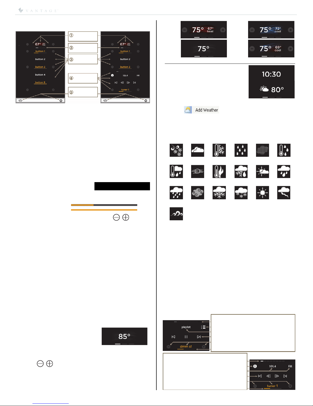
•Headers; select one of the following as a page header:
oempty – displays nothing in the header;
otemperature (only select one);
Internal temperature
External temperature
Heat set point
Cool set point
othermostat (select one thermostat only);
Displays internal temperature
Displays current mode setpoint – setpoint is
adjustable via minus / plus (-/+) buttons
Displays current mode – blue graphic for Cool,
red graphic for Heat, blue and red graphic for
Auto, and gray graphic for Off
Displays the word “heat” or “cool” and the
current mode graphic becomes more vivid when
system is actively heating or cooling
otime – HH:MM format;
twelve hour clock only
oweather;
Displays current outdoor temperature and a
graphic of current conditions.
•AV mode – selecting an AV zone replaces bottom two
scene buttons on all three pages with pre-designed
common AV interface controls.
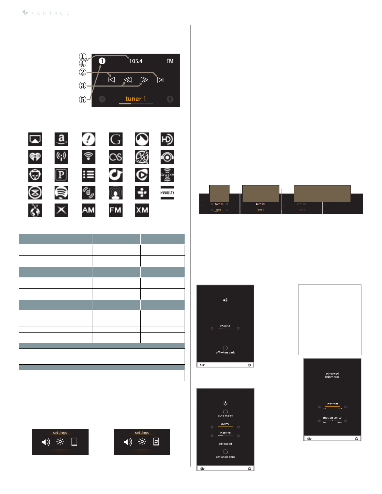
•Local settings (accessed by a press and hold of Home
button);
ovolume (touch interaction audio feedback)
minus / plus (-/+) touch interaction volume
off when dark checkbox
oSettings
Auto Mode option
Active & Inactive brightness settings
Advanced
•Low trim – sets minimum brightness
percentage for auto mode,
•Motion sense – sets proximity sensor’s
sensitivity.
Off When Dark option.
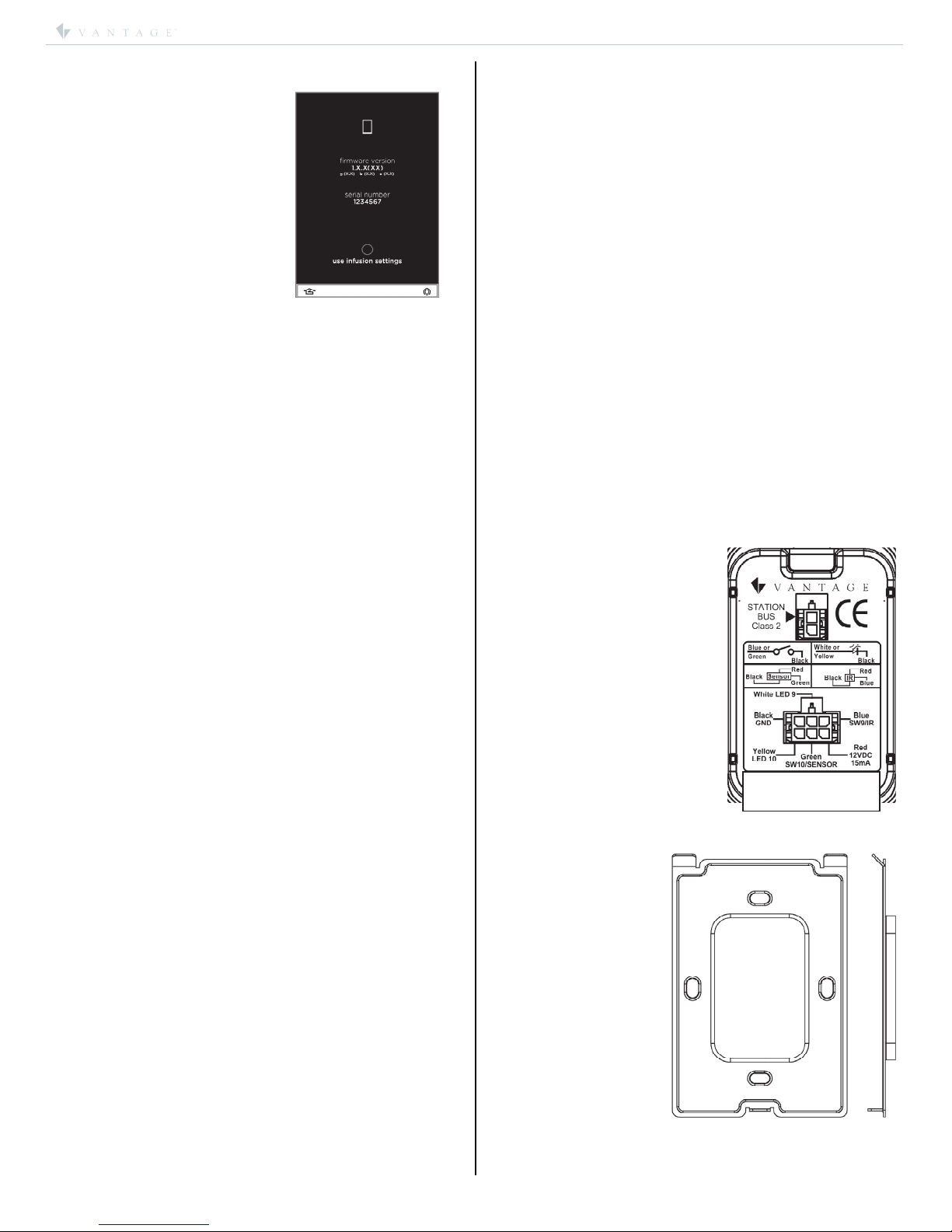
oStation information
Firmware, graphics, boot code & eprom versions
Serial number
use infusion settings,*(Design Center settings)
option.
*NOTE: to unselect use infusion settings change any
setting on the Sound or Brightness setup screens.
•Possible Screen Combinations:
1) Header, Scenes, Audio, 2) Header, Scenes,
3) Scenes, Audio, 4) Scenes only.
•Station Reset – simultaneously, press and hold both
mechanical buttons for one second. Do not touch the
screen when first powered or during the reboot process.
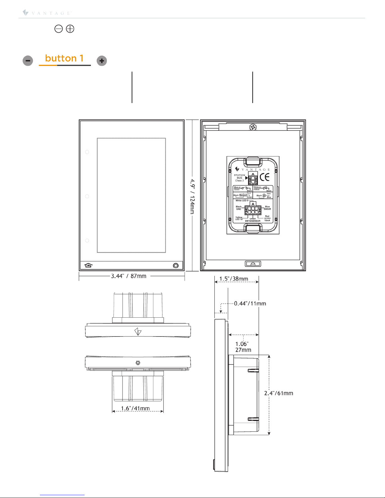
Specifications
Description Specification
Dimensions, HWD
(at wall surface)
4.9” x 3.44” x 0.44”
124mm x 87mm x 11mm
Dimensions, HWD
(overall)
4.9” x 3.44” x 1.5”
124mm x 87mm x 38mm
Finished Weight 11.2 oz. or 317.5g
Power 24V/36V via Station Bus
Surge Suppression Yes
Maximum LCD Control
Points (CP) including +/-
buttons (with 3 pages)
Scenes only – 45 CP max.
Scenes & Header – 47 CP max.
Scenes & AV – 37 CP max.
Scenes, AV, & Header – 39 CP max
Maximum Gangs Single Gang Only
LCD Button Status Automatic (white = off, ochre = on)
Sound Option
Independent volume for each sound:
1 – touch interaction
5 – programmable event sounds
Wiring Connections 2 Wire 600V pigtail (included)
6 wire aux. pigtail (order separate)
Power for Aux. External
Devices 15 mA @ 12V DC
Station Bus Polarity Auto-Switching
Station Wiring
configuration Daisy-chain/Star/Branch
Station Bus Specification
2C, 16AWG / 1.31mm2, twisted, non-
shielded, <30pF per foot. Separate a
minimum of 12" / 30.5cm from other
parallel communication and/or high
voltage runs.
Station Buss Power Draw 2.85W on IC-24 / 2.85W on IC-36
Addressing self addressing through software
Finish •TRIM - Titanium
•TOUCHSCREEN – Black Glass
Glass Surface Chemically Strengthened
Ambient Operating
Temperature 32-95°F -or- 0-35°C
Ambient Operating
Humidity 5-95% non-condensing
FreeRTOS™
Real-time scheduling provided by
FreeRTOS (www.freertos.org)
CE and RoHS Compliant Yes
Character / Font Support
Equinox can render the following Unicode Codepoints*
Range Typeface Unicode Codepages (blocks)
U+0000 -
U+00FF
Rendered in
Gotham Book Basic Latin, Latin-1 Supplement
U+0400 -
U+06FF
Rendered in Arial
Unicode MS
Cyrillic, Cyrillic Supplement,
Armenian, Hebrew, Arabic
U+2700 -
U+27FF
Rendered in Arial
Unicode MS Dingbats
U+3000 -
U+30FF
Rendered in Arial
Unicode MS
CJK Symbols and Punctuation,
Hiragana, Katakana
*NOTE: Proper computer/keyboard setup or copy/paste is
required to produce many international characters from the
above Unicode Codepoints.

I N S T A L L A T I O N
©Vantage, 7/23/2015 / IS-0541-A Equinox 40 LCD Keypad – MODEL: EQ40TB-TI-II page 2 of 6
Station Bus*
Enclosure
Equinox
Keypad
Equinox
Keypad
Six Wire Pigtail
for sensors, dry
contacts, etc.
Equinox 40
keypad
pigtail
mounting
plate
Equinox 40
LCD keypad
station bus
Screws*
*Use flat-head screws provided
US – 6-32 x 0.75″or
Metric – M3.5 x 20mm
Set 1/16” hex
screw in
station bottom
Press here on front,
bottom, center
System Requirements
Equinox 40 is compatible with InFusion Design Center version
3.1 software or higher. For new projects it is recommended
that firmware and software be kept to the most current
release.
Installation
Installation of Vantage products should be performed or
supervised by a Certified Vantage Installer. The Vantage
Equinox 40 keypad installs into US/European style, single
gang, wall boxes or low-voltage brackets. Connect to station
bus. See Troubleshooting, Expectations and Tips page 5. Do
not touch the screen when first powered or reset until it boots.
I. Installation Overview
*See Vantage Station Bus Specification – table, page 1.
Vantage Station Bus may be ordered separately.
Station Install Steps
1. Run station bus to boxes.
2. Install mounting plate with screws provided (see A in *Side
View Illustration). Do not bend mounting plate
3. Connect pigtail to station.
4. Install station by rotating (see B in *Side View Illustration)and
connecting the top first. Then press station in and hold on
bottom center while securing the hex screw with provided
allen wrench (see C in *Side View Illustration).
*Side View Illustration:
CAUTION: Do not over tighten the 1/16” hex screw in station
bottom. If screw will not go in, the mounting plate may need
slightly loosened and/or have a thin spacer inserted between
the wall and mounting plate. The wall must be repaired if
there is still a problem.
Auxiliary Connections
Auxiliary connections to the
station are wired to a six wire
pigtail, including motion
detectors, door contacts, light
sensors, etc. Each aux.
connection supplies a 15mA @
12V DC power source,
eliminating the need for an
external power supply. Aux.
powered devices using the
Black wire should not be earth
grounded unless isolated.
II. Configuration
1. Connect station bus and confirm it says ready.
2. Highlight station in Design Center; click Configure Stations.
3. Station displays tap to configure – tap station.
4. When configured station goes back to ready until
programmed.
-OR-
5. The station may also be configured by typing the serial
number in the project file, using this method the station will
automatically be configured when the system is
programmed.

I N S T A L L A T I O N
©Vantage, 7/23/2015 / IS-0541-A Equinox 40 LCD Keypad – MODEL: EQ40TB-TI-II page 3 of 6
33%
100%
Headers
Page
Indicators
Custom Scene
Buttons
AV
Controls
Mechanical
Buttons
spotsspots
Playlist Control &Status Icons
selected source dashes: – swipe left or right
source icon – press / release
playlist | ellipsis – press / release
skipprevious | pause/play | skipnext
volume — | source name/zone power | volume +
volume level indicator
Tuner Radio Control &Icons
selected source dashes: – swipe left or right
tuner presets (see Tuner Operation Detail):
frequency: - press / release | band icon
seek previous | tune up/down | seek next
volume — | source name/zone power | volume +
volume level indicato
r
III. Design Overview
Keypad Areas:
1. Headers – top portion of keypad, may be set to:
•Empty,
•Temperature,
•Thermostat,
•Time,
•Weather.
2. Page indicators 0, 2, or 3 dashes – beneath header:
•In Design Center, setup the Equinox keypad with 1, 2, or 3
pages. Dashes are added for two and three page layouts.
oUse a left or right swipe gesture to navigate the
pages.
3. Scene Buttons – middle portion of keypad:
•Button text uses a variable width font, allowing approx. 9 to
15 lower case characters & spaces that change color for
status. In Design Center, text turns red if text is to long.
oWhite = off and ochre = on.
•Dimmable load tasks, in addition to text, also display a
horizontal load level indicator.
oExample:
•Dimmable loads/tasks also display , –/+
(minus/plus) buttons that support press and hold for fading
or ramping and press and release for stepping down or up.
4. AV Zone – bottom portion of keypad:
•When enabled, the AV Zone replaces the bottom two scene
buttons on all three pages. Using a mini-widget, common
AV controls are automatically programmed.
oAV controls are dynamic and self-changing
depending on the AV Zone’s source equipment and
the Driver Designer, driver used.
oVantage’s 850D-DA and NūVō® or DMM-4S-(T) are
great examples using this integration. (See AV Zone
below)
5. Mechanical Buttons – bottom bar left/right buttons:
oPressing the home (mechanical) button on the
bottom left will return to page 1.
oPress and hold the home button for station setup.
oNote: The right button may have a task assigned to it.
IV. Equinox Headers and AV Zone Graphics Overview
Headers
•Empty – may be left blank.
•Temperature Header Widget
oSelect thermostat sensor or
setpoint property, (e.g., indoor
or outdoor temperature)
oDisplays sensor or setpoint value.
•Thermostat Header Widget:
oSelect one thermostat.
o, –/+ (minus/plus) buttons change the current
mode’s setpoint.
oThe text heat or cool appear under the setpoint when
the call for either is active.
Heat
Cool
Off
Auto
Time Header:
oDisplays current time in
hours and minutes.
•Weather Header Widget:
oSelect Header Data Weather.
oCreate Weather Data in
Design Center’s
programming view. To create
a location, right click and select the Add Weather
icon.
oWeather Location formats may be typed in as:
(1) City, State, (2) City, Country, or (3) U.S. Zip Code.
oWeather Icons and Descriptions
Current Condition icons are updated
automatically from Vantage’s weather service
provider.
blizzard cloudy cold day drizzle dust freezing
drizzle
freezing
rain
hazy hot day mixed partly
cloudy
rain
rain
showers
smoke snow snow
showers
sunny thunder-
storm
wind
AV Zone
•May be left blank:
oAllows for two additional scene buttons at the
bottom of all three pages.
•Select an AV Zone:
oIn Design Center, select a multi-room zone or filtered
zone; for example select Zone 1 from the 850D-DA
Amplifier. The sources available to that AV Zone and
the current source selected determine the controls
that will be available in the AV section of the keypad.
oVantage recommends naming sources with short
names using lower case letters. Equinox changes all
text to lower case characters in each source name.
Examples; dmm s1 or technics s2.
oSome AV Zone display icons are dynamic to include
appropriate information and/or interface controls
depending on the source selected.
Example: If the selected source is a DMM
playlist or an AM/FM tuner, the control buttons
and other metadata update automatically.

I N S T A L L A T I O N
©Vantage, 7/23/2015 / IS-0541-A Equinox 40 LCD Keypad – MODEL: EQ40TB-TI-II page 4 of 6
after 30s / no
plus/minus or
load levels
after another 30s,
(1 minute total) the
screen goes inactive or off
active
NOTE:
Play Sound Effects is
available through Design
Center programming. In
the Procedure Wizard,
Select Advanced | Stations
| Play Sound Effect. This
feature does not change
the Equinox interaction
sound when touching the
screen. Uses would be as
an alert triggered by a
motion sensor, etc.
Sound
(left)
touch interaction
configuration
s
creen
Brightness (below, left) –
(active / inactive)
configuration screen and advanced
A
dvanced Brightness (above, right)
Low trim – sets minimum brightness percentage
in auto mode,
Motion sense – proximity sensor’s sensitivity.
•Tuner Operation Detail
Each Equinox 40 station, on a project, supports six,
independent, learnable presets for each tuner/band source
available to the assigned AV Zone. Follow steps in order.
1. Press/Release on
frequency to
select presets 1–6.
2. |< or >|, seek
3. << or >>, tune to
station
4. Press and hold
frequency to
learn to selected
preset.
5. Preset selection turns white when learned.
oAV Source Icons and Descriptions
Icons are updated automatically from selected
source driver.
AirPlay Amazon Aupeo! GoogleMusic GrooveShark HDRadio
IHeartRadio InternetRadio2 InternetRadio LastFM MediaFly MOG
Napster Pandora PlayLists rdio Rhapsody SiriusXM
Slacker Spotify Stitcher StreamingMedia TuneIn
Wolfgang’s Vault
VTuner XBoxMusic AM FM XM
Binding Methods, Substitutions, and Driver Implementation
Play
Interface
Standard
Binding Method
Binding Method
Substitute 1
Binding Method
Substitute 2
|< SkipPrevious Rewind ScanPrevious
|| Pause — —
> Play — —
>| SkipNext Forward ScanNext
Tuner
Interface
Standard
Binding Method
Binding Method
Substitute 1
Binding Method
Substitute 2
|< SeekDown ScanDown —
<< TuneDown — —
>> TuneUp — —
>| SeekUp ScanUp —
Channel
Interface
Standard
Binding Method
Binding Method
Substitute 1
Binding Method
Substitute 2
|< ScanDown CategoryPrevious
(Tuner Interface) —
<< Down — —
>> Up — —
>| ScanUp CategoryNext
(Tuner Interface) —
Zone Switching Implementation
Drivers utilizing switching for the Equinox 40 must support the AVZone2
model with implementation of the AVZone2, AVSource, Power and
Volume2 interfaces.
Media Server Implementation
Media server support must implement the data provider interface using
the Equinox 40 data model.
V. Equinox 40 Configuration Pages
Setup – To enter the settings screens, press and hold the Home
button for about 2 seconds (mechanical button, bottom left).
Press and hold again to select a different settings page or
press and release to exit.
•Setup Screen – displays three choices
Using Local Settings Using Design Center settings
(notice icon on right)
Press and hold the home button to select one of the following
three categories:
•Sound Settings – touch interaction feedback
•Adjustable volume level
•off when dark check box
•Brightness Settings
•auto mode check box – auto sets active brightness to
ambient light
•active – sets active brightness level
•inactive – sets brightness to inactive level after 60
seconds of non-use
•advanced (advanced brightness)
Low trim – sets minimum brightness percentage
for auto mode,
Motion sense – sets proximity sensor’s
sensitivity level.
•off when dark – when checked turns LCD screen off, if
ambient light level is very low, when going to inactive
level.
Steps moving from active to inactive
•after 30 seconds the minus/plus buttons and load
levels dissappear.
•After another 30 seconds (1 minute total) the screen
dims to inactive level or off, if off when dark is
checked and ambient light is very low.
•Information Settings
Station firmware version
G(xx), B(xx), & E(xx) – graphics, boot, and eprom
versions
Station serial number
use infusion settings check box*
*Note: To uncheck the use infusion settings check box, make
changes to the Sound or Brightness settings.
Configuration Screens:

I N S T A L L A T I O N
©Vantage, 7/23/2015 / IS-0541-A Equinox 40 LCD Keypad – MODEL: EQ40TB-TI-II page 5 of 6
Information (right)
Firmware*
,
graphics, boot code, an
d
eprom versions & use infusion settings
configuration screen.
NOTE: Firmware may be update
d
from Design Center. Screen turns a
g
radient green color during a
firmware update.
Close-Up of Back
Label
(Configuration Screens continued)
Troubleshooting, Expectations and Tips
1. Header Widget Area - Comfort/Weather/Clock/Blank
Provides relevant thermostat, weather or clock information
•Thermostats Supported – Vantage CC-STAT and
Aprilaire 8870 or 8800, including internal and external
temperature sensors – thermostat in thermostat mode
only – no support for Humidistat.
•Weather Supported – Current outside temperature and
conditions.
Tips/Troubleshoot -
•Auto Mode – last known mode setpoint shown, +/-
buttons increment BOTH heat and cool modes at the
same time, unknown currently if it is heat or cool when
walked up to.
•Weather – check gateway and DNS on controller
•Time – may take up to one minute to synchronize with
system time if controller time is changed.
2. Middle Button Area – Scenes/Tasks
Provides standard button control and feedback for any scene
•Supported Button Count – Max three per page with
audio; Max five per page without audio
•Supported Page Count – Max three
•Supported Scenes – All Vantage tasks for lighting,
shades, a/v, pool/spa, drivers, conditional logic, etc.
Tips/Troubleshoot -
•+/- Buttons – Check conditional logic on tasks, confirm
power profile standard/dimmable (use of simple
conditional logic and dimmable loads).
Supported Cases –
1. Procedures and loads support adjust/dimmable.
2. All devices are same type (no mixed scenes).
3. Same objects in all branches of conditional logic.
4. Dimmable Loads required (for loads)
a. If all power profiles are relay, adjust/dim is
not supported
5. Make sure all objects support required methods
•LED Status – Status using fixed colors for ON and OFF.
•Character counts – based on non-proportional
characters used, typically 9-15. Turns red if too long.
•No Capital letters – not allowed based on Industrial
Design guides.
•Button allocation on Pages – only draws pages with
buttons assigned, Only draws buttons if text or task
assigned
3. Bottom AV Widget Area – Audio Zone/Sources
Provides single zone audio control for power, volume, source
selection, playlists, tuner presets and transport commands.
•Supported Multi-room Systems – Vantage 450, 850, and
Nuvo Grand Concerto.
•Sources Supported – Vantage DMM, Vantage IMS,
Autonomic Mirage MMS - playlists & Pandora, Mozaex
Solo (use DMM object renamed), Nuvo Music Port, Nuvo
T2, Nuvo iPod Dock, Russound ST2, Speakercraft STT2,
Elan DTNR, Onkyo T4555, Integra TUN 3.7, iPort FS/IW.
Tips/Troubleshoot -
•Initially tuner presets are empty; the initial project file
does not have tuner presets.
•Tuner presets are read back in from system every time
there is full program or firmware update once they exist.
Project file must be open for read back to work and
then saved.
•Tuner presets are lost if keypad is deleted from Design
Center project.
•Check to see if using supported drivers
•Check source parameters for drivers assigned
•Check AV zone or filtered AV zone selections
•Check firmware on 450/850
•Check to see if using unsupported drivers, IR (discrete
play/pause), interfaces implemented?
•Check source parameters, check zone parameters
•For unsupported systems use keypad/scene buttons
Firmware Update / Boot Code Operation Mode -
If station appears to be locked and will not accept a firmware
update from Design Center, place the station in boot code
operation mode.
•Press and hold both buttons until station resets.
•Release left button and a second later the right button.
•The screen will turn to gradient green and should now
accept a firmware update from Design Center.
•Firmware updates to EQ40 screens take just under
three minutes-approximately.
•When the firmware update is complete the station
should automatically boot to normal application mode.
Back Label (right)
Mounting Plate
Use flat-head screws
provided to mount the
Mounting Plate.
Pan-head screws will not
allow the station to fit
snugly to the wall and
may damage
electronics. Do not bend
mounting plate.
Use either type screw
supplied:
•2 Each – US:
o
US: VHC-01090–
SCREW, 6-32 X .750”
P-FH, ZINC
•2 Each – Metric:
o
VHC-01089–SCREW,
M3.5 X 20mm P-FH,
ZINC

I N S T A L L A T I O N
©Vantage, 7/23/2015 / IS-0541-A Equinox 40 LCD Keypad – MODEL: EQ40TB-TI-II page 6 of 6
Multi-View Line Drawing
Please see http://dealer.vantagecontrols.com
/
for latest installation instruction.
Equinox 40 –/+ (minus/plus) Adjust Buttons Descriptions For Press and Release or Press and Hold
The following task procedures will cause the Equinox 40 to display the –/+ (minus/plus) adjust buttons and status bar.
The percentage of change when tapping the minus/plus buttons is adjustable in Design Center by clicking on Settings | Procedure
Preferences | System Defaults and adjusting the Bump Percentage (default is 10%).
•Dim
•Dim Cycle
•Dim Scene
•Off with Lower
•On with Raise
•Default Dimmer Behavior
•Toggle
•Toggle With Auto Off
•Toggle With Auto Learn
•On
•On With Auto Off
•On With Auto Learn
•Standard Fan Control
•Set Blind Position
•Set Volume (Volume2)
Other Vantage Hearth Keypad manuals
Popular Keypad manuals by other brands

Carlon
Carlon HS4317D Instruction guide

Universal Remote Control
Universal Remote Control Total Control TKP-7000 owner's manual

Elite Suite
Elite Suite ELT-KLED installation manual

Magellan
Magellan MG32I User quick reference guide

Blink Marine
Blink Marine PKP2500SI manual

Russound
Russound DAN instruction manual

Manhattan
Manhattan 178846 instructions

Targus
Targus Numeric Keypad with 2 USB ports user guide

Bosch
Bosch D202A Series Technical specifications

Cooper
Cooper Scantronic 524 installation guide

Crestron
Crestron AirMedia ZUMMESH-KP10AMBATT quick start guide

GE
GE NX-148E - Security NetworX LCD Keypad user manual