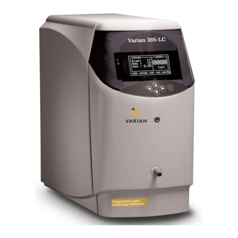
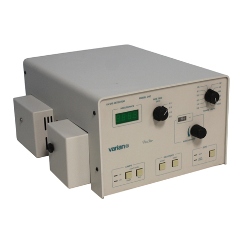
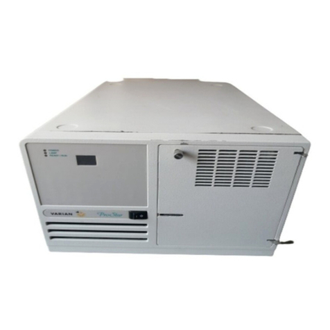
Varian ProStar 325 UV-Vis User manual

ProStar 325
UV-Vis Variable Wavelength Detector
Service Manual
Installation Category II
Pollution Degree 2
Safety Class 1 (EN 61010-1)
Publication Number
85 102009 00
StockCheck.com

ProStar325 Service Manual
2
Publication date 8 May 2003
This page is intentionally left blank.
StockCheck.com

ProStar325 Service Manual
Publication date 8 May 2003
3
Varian has offices in most countries. The major offices for optical
spectroscopy products are listed below:
Varian Australia Pty Ltd (Manufacturing site)
679 Springvale Road,
Mulgrave, Victoria 3170
Australia
International telephone: + 61 3 9560 7133
International fax: + 61 3 9560 7950
Varian Inc.
2700 Mitchell Drive,
Walnut Creek, CA 94598 USA
Phone: 1 800 926 3000
International telephone: +1 925 939 2400
International fax: +1 925 945 2102
Varian BV
Herculesweg 8,
4330 EA Middelburg
The Netherlands
International telephone: +31 (0) 118 671 000
International fax: + 31 (0) 118 633 118
Internet
The Varian Internet home page can be found at:
http://www.varianinc.com
Varian Australia Pty Ltd. is the owner of copyright on this
document and any associated software. Under law, the written
permission of Varian Australia Pty Ltd. must be obtained
before either the documentation or the software is copied,
reproduced, translated or converted to electronic or other
machine-readable form, in whole, or in part.
Comments about this manual should be directed to the
Marketing Communications Manager, Varian Australia at the
address above or by Email to webmaster@osi.varian.com.
Varian Australia is ISO9001 certified.
© 2002 Varian Australia Pty Ltd. (A.C.N. 004 559 540) All
rights reserved.
® Windows 98, Windows 2000and Windows NT are registered
trade marks of Microsoft Corporation.
StockCheck.com

ProStar325 Service Manual
4
Publication date 8 May 2003
Table of Contents
Section 1
1General Information ................................................9
1.1 How to use this manual 9
1.1.1 Finding Information 9
1.2 General Information 10
1.3 Design features 10
1.4 Fundamentals of the ProStar 325 detector 11
1.5 Detector performance testing 12
1.6 Safety practices and hazards 13
1.6.1 Electrical hazards 13
1.6.2 Lamp source 13
1.6.3 Panels and covers 14
1.6.4 Other precautions 14
1.7 Service philosophy 15
1.7.1 Varian customer support policies 15
1.7.2 Service policy 15
1.7.3 Spare parts policy 15
1.7.4 Warranty 15
1.7.5 OEM Warranty 16
1.7.6 Contract maintenance 16
2Pre-Installation......................................................17
2.1 Information symbols 17
2.1.1 Warnings and Cautions 17
2.2 Pre-installation checklist 21
2.2.1 Pre-installation complete 21
2.3 Weights and dimensions 22
2.4Environmental conditions 22
2.5 Workbench 24
2.6 Electrical specifications 24
2.6.1 Mains supply 24
2.7 Fuses 25
2.8 External connections 25
StockCheck.com

ProStar325 Service Manual
Publication date 8 May 2003
5
2.9 Equipment on-site 26
2.9.1 Insurance 26
2.9.2 Inspection for transit damage 26
2.10 Computer interface 27
2.10.1 Computer requirements 27
2.10.2 Ethernet 28
2.10.3 Recommended printer/plotter 28
2.11 Setting up your PC 28
2.11.1 ProStar 325 Verify software 28
2.12 Operator training 29
3Installation............................................................30
3.1 Introduction 30
3.2 Pre-installation 31
3.3 Installation times 32
3.4 Before you start 32
3.5 Installation 33
3.5.1 Installation guide 33
3.6 Installation of Door Cap 34
3.7 Installation and Removal of Door 35
3.8 Software Installation 36
3.9 Ethernet connection 37
3.9.1 Networks 37
3.9.2 Where to Begin 38
3.9.3 Installing and Configuring the Ethernet Card in Your
PC 39
3.9.4 Configuring TCP/IP Parameters with No Company
Network 41
3.9.5 Configuring TCP/IP Parameters for a Company
Network 43
3.10 Hand Held PC connection 45
3.11 Instrument setup 46
3.12 Synchronization Signals at P9 and J10 47
3.13 Rear Panel Accessory Interface PWB 49
3.14 Rear Panel Relay Interface PWB 49
3.15 Electrical connection 49
3.16 Fuses 50
3.17 Power Up 50
StockCheck.com

ProStar325 Service Manual
6
Publication date 8 May 2003
3.18 Front Panel LEDs 50
3.19 Detector States 51
3.20 Instrument performance tests 53
3.21 Flowcell 55
3.21.1 Tubing 56
3.21.2 Flowcell storage 58
3.21.3 Cleaning the flowcell 58
3.21.4 Flowcell types 59
3.22 Back pressure restrictor 60
3.23 Extended range 60
3.24 Source lamps 60
3.25 Cleaning 61
3.26 Excessive Noise and/or Drift 61
4Electronics ............................................................64
4.1 Introduction 64
4.2 OEM power supplies 64
4.2.1 Low voltage power supplies 64
4.2.2 Deuterium (D2) lamp power supply 65
4.2.3 Visible lamp power supply 66
4.3 Processor PWB 67
4.3.1 Processor PWB functions 67
4.3.2 Non Volatile Data Storage 70
4.3.3 Signal processing and A to D conversion 70
4.3.4 Relay Outputs 71
4.3.5 Peak Sensing 71
4.3.6 Analog Output 71
4.3.7 Calibration 73
4.3.8 Dual Wavelength 73
4.4 Initialization Sequence 74
4.5 LEDs and diagnostic display 74
4.5.1 Seven segment displays 74
4.6 Diagnostic select switch 75
4.7 Dual Photodiode pre-amp PWB 76
4.8 LED – IrDA display PWB 77
4.9 Removal & replacement procedures 77
4.9.1 Processor PWB 77
StockCheck.com

ProStar325 Service Manual
Publication date 8 May 2003
7
4.9.2 Dual Photodiode PWB 81
4.9.3 LED – IrDA PWB 81
4.9.4 Power Supplies 82
4.9.5 Fan replacement 83
4.9.6 Fuses 83
5Optics....................................................................85
5.1 Introduction 85
5.2 Optics module 85
5.2.1 UV lamp assembly 85
5.2.2 Visible lamp assembly 86
5.2.3 Monochromator 86
5.2.4 Optical path 87
5.3 Removal and replacement procedures 90
5.3.1 UV lamp source 90
5.3.2 Vis lamp source 92
5.3.3 Optics module 93
5.4 Installing Vis lamp option 96
5.4.1 Optimizing Vis lamp 99
5.5 Performance test 101
6Spare parts ..........................................................102
Location of major assemblies 102
6.1 Covers 102
6.2 Electronic spare parts 102
6.3 Optical spares parts 103
6.4 Upgrade kits 104
6.5 System cables 104
6.6 Miscellaneous 104
7Diagnostics..........................................................105
7.1 Introduction 105
7.2 Power On Self Test (POST) 105
7.3 Power up sequence 105
7.4 LED status indicators 106
7.5 PWB selector switch tests 106
7.6 Diagnostics CD 108
7.6.1 Introduction 108
7.6.2 Functions of Diagnostic.exe 108
StockCheck.com

ProStar325 Service Manual
8
Publication date 8 May 2003
7.6.3 Menu task bars 109
7.6.4 Status bar 109
7.7 Main Display 110
7.8 Method Development 111
7.8.1 Building a method 111
7.8.2 Modifying a method 112
7.8.3 Downloading a method 112
7.8.4 Saving a method 113
7.9 Detector Status 113
7.9.1 Main 113
7.9.2 Internal Method 114
7.9.3 Logs 115
7.9.4 Alarms 115
7.10 Diagnostic Functions 116
7.10.1 Input/Output 117
7.10.2 EEPROM 118
7.10.3 Mono Options 119
7.10.4 Gain and Dark Tables 121
7.10.5 Comms 123
7.11 Establishing communications 124
7.12 Calibration 125
7.12.1 Mono 125
7.12.2 0% Transmission 128
StockCheck.com

ProStar325 Service Manual
Publication date 8 May 2003
9
StockCheck.com

ProStar325 Service Manual
10
Publication date 8 May 2003
1General Information
This publication supplies information that allows a Varian-
trained, Varian-qualified or Varian-authorised Customer Service
Representatives to maintain and service the ProStar 325
detector. If the product is used in a manner not specified by
Varian, the safety protection that is inherent in the design may
be impaired.
The UV-Vis detector contains high voltages, and improper or
unskilled use of it can cause death, serious injury or damage to
equipment and property.
All users of the ProStar 325 detector must be familiar with the
correct operating procedures. Site preparation and guidelines are
described in the pre-installation section of this manual and in the
Hardware Operation Manual publication number 85-102016-00.
The detector and accessory covers must not be removed by the
operator under any circumstance.
1.1 How to use this manual
The safety practices and hazards section described below is
provided to help the user operate the detector safely. Read these
safety practices thoroughly before attempting to operate the
detector, and always operate the detector in accordance with
these safety practices.
The detector system uses interlocks and covers which are
designed to prevent inadvertent contact with any potential
hazards. It is good practice to develop safe working habits, which
do not depend upon the correct operation of the interlocks for safe
operation.
It is essential that interlocks are not bypassed, damaged or
removed and all covers are properly installed when operating the
detector.
All information contained in this publication is relevant to the
ProStar 325 detector.
1.1.1 Finding Information
There is a comprehensive Table of Contents in the front section of
the manual detailing each chapter.
Electronic and mechanical schematics including layouts and
assembly drawings are included in the Schematics section of the
manual.
Ordering information for spare parts is in the Spare Parts section
StockCheck.com

ProStar325 Service Manual
Publication date 8 May 2003
11
which lists a comprehensive list of spares and their part
numbers. Where possible, pictures are used to illustrate a part
for visual identification.
Service manual updates will be provided by Varian when
necessary and will come in the form of diskette README file,
Service Alerts or Service notes.
1.2 General Information
This section provides an overview of the ProStar 325 detector and
contains important information on;
•Design features
•Fundamentals of the ProStar 325
•Safety practices and hazards
•Service philosophy
1.3 Design features
Design features include:
High performance photodiode detectors
Quartz over-coated optics
Deuterium arc ultraviolet source
Tungsten halogen visible source with quartz window
Double-beam, ratio recording, Czery-Turner monochromator
Choice of four precision flowcell varieties
Stackable module
Simple lamp replacement performed by the user
Flowcells can be easily replaced by the operator
Ethernet TCP/IP network configuration
Remote access
Pocket PC compatible using infra-red link
Fully compatible with current ProStar modules
Model upgradeable through firmware
StockCheck.com

ProStar325 Service Manual
12
Publication date 8 May 2003
1.4 Fundamentals of the ProStar 325 detector
The ProStar 325 detector is a variable wavelength UV/Vis
detector that can be operated as a standalone HPLC detector
with a Pocket PC (PPC) as the Controller, or it can be controlled
remotely from a Star or Galaxy workstation. Using various
combinations of flowcells and lamps, the detector can be adapted
for applications from analytical to preparative levels. On the
front panel there are no controls apart from the power ON/OFF
switch and three LED indicators. The host computer is
responsible for sending and receiving data and for performing all
computations including the storage and display of results.
The detector measures the sample absorbance at the user
selected wavelength. The absorbance is output as an analog
signal to an external chart recorder and/or data collection system,
or as a digital signal to Star Workstation or Galaxie. Wavelength
absorbance parameters are time programmable on the
standalone unit. This manual instructs the user in the
installation and operation of the 325 detector for non-
Workstation operation, e.g. with the Pocket PC controller.
The detector’s advanced optical design, electronics, photo diode
detectors and range of precision dual-path flowcells, make the
ProStar 325 a versatile detector capable of operating in different
modes. The detector can come in four different configurations;
single-wavelength with deuterium lamp
single-wavelength with deuterium and quartz visible lamp
dual-wavelength with deuterium lamp
dual-wavelength with deuterium and quartz visible lamp
A single wavelength detector can be upgraded to dual wavelength
detector by a firmware download as an optional extra at any
time. This gives the detector its distinct advantage of having
StockCheck.com

ProStar325 Service Manual
Publication date 8 May 2003
13
variations of a common base model that can be configured for
each individual application.
If fitted with the optional Vis lamp, the detector operates across
the entire spectrum from 190nm to 900nm. Both lamps are
continuum lamps and only one should be selected at a time.
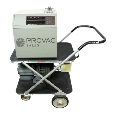
Wavelength selection is provided by a holographic grating driven
by a stepper motor drive mechanism.
A silica glass beam splitter provides double beam operation. The
two beams are individually passed through the optics system and
into the monochromator and then to their respective photodiode
detectors.
lll
Simplified Optical System
For increased performance the two channels are separated and
the photodiodes are connected to individual preamplifiers. The
preamplifier output voltages are directly proportional to the light
intensity hitting their active surfaces.
The outputs of the preamplifiers are digitised, processed, and
either sent to a pc, or re-converted to analog. The analog circuitry
produces a voltage directly proportional to the ratio of the sample
signal to the reference signal. This voltage is supplied to the rear
panel as the 1V/AU integrator output and as a recorder output.
For extra flexibility, the 325 detector can also be controlled via a
hand-held PPC. You can use the PPC to download, build and
store methods from the host computer, and have full functional
control of the detector via an infra-red communications link.
The detector is compatible with the current ProStar range of
products and operates under the control of the Star or Galaxie
software workstation software. Communication to the host PC is
via an Ethernet TCP/IP link operating up to 100Mbps. This high-
speed connection enables real time representation of the
spectrum displayed on the workstation. Further more, it also
allows the detector workstation to be integrated into a TCP/IP
protocol LAN to enable remote access to any detector over an
internet connection.
There are also four flowcell options for the detector at present;
Beam
splitter
lamp
sample
referenc
grating
sample reference
Photodiode
detectors
StockCheck.com

ProStar325 Service Manual
14
Publication date 8 May 2003
9x0 Analytical
9x1 Preparative
4x0.15 Super Preparative
4x0 Semi Micro
The flowcell bodies are constructed from titanium and are
provided with quartz optics windows. Tubing connections are
PEEK except for the Super Prep flowcell which uses TEFZEL
TUBE 0.125 x 0.062.
Each flowcell is easily interchangeable by the user.
1.5 Detector performance testing
Detector performance tests are provided in the Verify software
application. The set of tests available include;
Short and long term signal-to-noise
Short term dual wavelength signal-to-noise
Stability
Wavelength accuracy
Wavelength repeatability
Detector linearity (stray light)
Refractive index sensitivity
Spectral bandwidth
Autozero precision
Cell length ratio
Cell precision
The results of all tests performed using the Verify package are
automatically stored by the system in the software directory.
1.6 Safety practices and hazards
Information on safety practices appears throughout the
documentation provided with your detector. Before using the
detector you must thoroughly read these safety practices.
If the equipment is used in a manner not specified by the
manufacturer, the protection provided by the equipment may be
impaired.
Observe all relevant safety practices at all times.
1.6.1 Electrical hazards
The ProStar 325 detectors contain electrical circuits, devices, and
components operating at dangerous voltages. Contact with these
circuits, devices and components can cause death, serious injury
or painful electrical shock.
StockCheck.com

ProStar325 Service Manual
Publication date 8 May 2003
15
ONLY Varian-trained, Varian-qualified, or Varian-approved
Customer Service Representative (CSR) may open panels or
covers, which are retained by screws on the detector. Consult the
manuals or product labels supplied with the PC, monitor and
printer/plotter to determine which parts are operator-accessible.
Operators and other unauthorized personnel are permitted access
ONLY to the lamp sources for replacement. ALWAYS switch off
the detector before changing a lamp.
Good grounding is essential to avoid a potentially serious electric
shock hazard. Ensure that there is an integral ground connection
between the metal base of the detector and the 3 pin earth-
grounded receptacle.
Note that the safety classification is given as Class 1 (EN 61010-
1). The PC must comply with IEC 60950.
Application of the wrong supply voltage can create a fire hazard
and a potentially serious shock hazard and could seriously
damage the ProStar 325 system and any attached ancillary
equipment.
Replace blown fuses with fuses of the size and rating as
stipulated in the text adjacent to the fuse holder at the rear of the
detector or, as specified in the manual.
Never use power cords with faulty or frayed insulation.
1.6.2 Lamp source
The UV and Vis lamps are enclosed in self-contained modules.
Both operate at high temperatures and touching either of these
may result in burns. Before replacing a lamp that has been lit,
switch the detector off and ensure that you either wait for the
lamp to cool, or protect your fingers from burns. The UV lamp
module operates at high voltages.
When operating, these lamp sources emit high intensity UV and
Visible light that can cause serious damage to eyes. To avoid eye
damage, never operate a lamp outside the detector.
NEVER look directly at the UV source lamp. ALWAYS wear safety glasses
manufactured to an approved standard and which are certified or otherwise warranted to
protect the eyes from UV radiation when the UV lamp is operating.
1.6.3 Panels and covers
Only the panel that provides access to the lamp compartments
and flowcell may be removed by the operator. All other panels or
covers that are retained by screws on the detector may be opened
only by Varian-trained, Varian-qualified or Varian-approved
StockCheck.com

ProStar325 Service Manual
16
Publication date 8 May 2003
Customer Service Representatives (CSR’s). Consult the manuals
or product labels supplied with your PC, monitor and
printer/plotter to determine which parts are accessible.
Operators and other unauthorised personnel are permitted access
only to the lamp compartments and Flowcell assembly.
Always switch off the detector before changing a lamp.
1.6.4 Other precautions
Do not block the rear ventilation grills on the ProStar 325. Make
sure you provide adequate space behind the detector for air
circulation, electrical, and communications cables.
Warning: The use of the ProStar 325 system may involve materials,
solvents and solutions that are flammable, corrosive, toxic or otherwise hazardous.
Careless, improper, or unskilled use of such materials, solvents and solutions can create
explosion hazards, fire hazards, toxicity and other hazards which can result in death,
serious personal injury, and damage to equipment and property.
ALWAYS ensure that laboratory safety practices governing the use, handling and
disposal of such materials are strictly observed. These safety practices should include the
wearing of appropriate safety clothing and safety glasses.
1.7 Service philosophy
1.7.1 Varian customer support policies
Warranty 12 months, though this may vary according to
location.
Hardware
support period 5 years from date of last unit manufacture. After
this time, parts will be provided if available.
StockCheck.com

ProStar325 Service Manual
Publication date 8 May 2003
17
1.7.2 Service policy
In the normal course of field servicing, it is Varian’s policy to
troubleshoot and repair to a modular level at the detector’s
location.
Software diagnostic routines are available to aid in fault
isolation. These are to be used in conjunction with conventional
test equipment to effect on-site repairs.
In situations where minimizing downtime is the prime
consideration board or module exchange should be considered,
but only after preliminary attempts to repair have proven
unsuccessful. Component level repair should not be attempted
outside a designated service repair centre. Electronic assemblies
such as the source lamp module and electronic boards with
surface mount components are not field repairable.
1.7.3 Spare parts policy
Operational spare parts for all Varian detectors and major
accessories will be held in stock for a period of five years after
shipment of the final production unit. Spare parts may be
provided after this five-year period, but only on an “as available”
basis. Operational spare parts are defined as those individual
electrical or mechanical parts that are susceptible to failure
through fair wear-and-tear during their normal operation.
Examples include resistors, inductors, capacitors, semi-conductor
devices, relays, lamps, temperature probes, detectors elements,
motors, wiring board assemblies and the like.
General hardware (for example, sheet metal parts, structural
members, assemblies and castings) will normally outlast the
useful life of the detector and therefore will only be supplied on
an availability basis after the final production unit is
manufactured.
Proprietary items and components that are unique to the Varian
equipment should be sourced from the Varian Service Centre.
Other components may be sourced locally unless otherwise
specified in this manual.
1.7.4 Warranty
All Varian products are warranted against defects in materials
and workmanship, but not against consequential damages. Full
details relating to the terms of warranty are available from any
Varian Sales and Service Office or Agency. No other warranty is
expressed or implied. Consumable items such as (but not limited
to) light sources, temperature probes and other glassware items
are subject to a limited or pro-rated warranty. The Varian
warranty provides for specific legal rights. There may also be
other rights that vary from country to country, or region to
region.
The warranty applies only to the installed Varian equipment, and
cannot be extended to cover the associated miscellaneous
StockCheck.com

ProStar325 Service Manual
18
Publication date 8 May 2003
installations that remain the customer’s responsibility. By the
same reason, the warranty does not cover problems that may be
caused by misuse of the equipment, wrong applications,
operator’s inexperience etc. Standard Warranty will cover 12
months, though this may vary according to location.
1.7.5 OEM Warranty
Personal Computers (PC’s), printers, modems other PC
accessories and OEM accessories used with the ProStar 325 are
not covered by the Varian detector warranty. Generally this type
of equipment is sourced locally and therefore local supplier or
vendor warrantees will apply.
1.7.6 Contract maintenance
After expiry of the warranty time, service and/or repair of Varian
detectors and accessories are handled on a time and materials
basis, in accordance with the Varian standard service or contract
maintenance arrangements. Quotations for contract maintenance
may be obtained from any Varian Sales Office or Service Centre.
StockCheck.com

ProStar325 Service Manual
Publication date 8 May 2003
19
StockCheck.com

ProStar325 Service Manual
20
Publication date 8 May 2003
2Pre-Installation
The ProStar 325 UV-Vis detector has been fully tested and
proven to specification before dispatch from the manufacturing
plant.
This chapter contains general information that is relevant to the
preparation of an installation site and details the facilities which
must be provided to ensure that the system can be effective.
Detailed operating procedures are provided in the operation
manual that is supplied with the detector.
For installations that are to be done by Varian personnel, you
should complete the Pre-installation Checklist contained in this
section. Strike out any entries not appropriate to your system,
and then send a copy of the checklist to the Varian Sales and
Service Office or local Varian agent dealing with the supply of the
equipment. On receipt of this document, the Varian Sales and
Service Office or local Varian agent will contact you and arrange
a convenient time for installation.
2.1 Information symbols
2.1.1 Warnings and Cautions
Specific warnings and cautions appear in this manual which
detail the hazard, describe how to avoid it, and specify the
possible consequences of not heeding the warning or caution.
Warning A ‘Warning’ message appears in the manual or on the
detector when failure to observe instructions or
precautions could result in death or injury. Symbols
depicting the nature of the specific hazard are also
placed alongside warnings.
Caution
A ‘Caution’ message is used when failure to observe
instructions could result in damage to equipment
(Varian supplied and/or associated equipment).
StockCheck.com
Other manuals for ProStar 325 UV-Vis
1
Table of contents
Other Varian Security Sensor manuals

Varian
Varian 990 CLD Autoline User manual

Varian
Varian ProStar 325 UV-Vis Release note

Varian
Varian Turbo-V60 User manual

Varian
Varian 380-LC User manual

Varian
Varian ProStar 340 User manual

Varian
Varian 948 Operation manual

Varian
Varian ProStar 363 Release note

Varian
Varian ProStar 335 Release note

Varian
Varian 959D User manual

Varian
Varian 979 Series User manual