Varimixer Flexlift INOX mini User manual

INSTRUCTION MANUAL
SERIAL NUMBER: ____________________
Varimixer A/S
Kirkebjerg Søpark 6
DK-2605 Brøndby
Denmark
P: +45 4344 2288
www.varimixer.com
SAP nr. 20060-1710
Version 1.1 UK
Original language "English"

EC- DECLARATION OF CONFORMITY
MachineryDirective2006/42/ECAnnexII A
Manufacturer and party responsible for compiling technical documentation:
Companyname:
Address:
Postal code:
Phone number:
Hovmand A/S
Sandvadsvej 15
DK-4600Køge, Denmark
+45 57 8333 00
www.hovmand.com
- herebydeclare that the machine:
Designation:
Type identification number:
Serial number:
Mobile battery-powered lifter
Flexlift INOXmini
_______________________
- is manufactured in accordance with the Machinery Directive 2006/42/EC Annex II A.
The following directives and standards as well as technical reports have been applied, insofar as theyhave
been found to be whollyor partlyrelevant in relation to the construction and design of the machine:
Directives: 2014/30/EC
2014/35/EC
2011/65/EC
Standards: EN/ISO12100: 2011
EN/ISO/TR14121-2: 2012
EN 60204-1: 2016
EN/IEC63000: 2018
EN/ISO3691-5: 2015
DS/EN ISO20607: 2019
Authorisation of HOVMAND A/S, to prepare technical documentation and communicate information about the
device, in response to anysufficientlymotivated request from state authorities:
Køge 15/12-2021
Søren Hovmand
Managing Director
Hovmand A/S

DECLARATION OF CONFORMITY
Supplyof MachinerySafetyRegulations 2008
Manufacturer and party responsible for compiling technical documentation:
Companyname:
Address:
Postal code:
Phone number:
Hovmand A/S
Sandvadsvej 15
DK-4600Køge, Denmark
+45 57 8333 00
www.hovmand.com
- herebydeclare that the machine:
Designation:
Type identification number:
Serial number:
Mobile battery-powered lifter
Flexlift INOXmini
_______________________
- is manufactured in accordance with the Supplyof MachinerySafetyRegulations 2008.
The following directives and standards as well as technical reports have been applied, insofar as theyhave
been found to be whollyor partlyrelevant in relation to the construction and design of the machine:
Directives: Electromagnetic CompatibilityRegulations 2016
Electrical Equipment SafetyRegulations 2016
RoHSRegulations 2012:GB
Standards: BS/EN/ISO12100: 2011
ISO/TR14121-2: 2012
BS/EN 60204-1: 2016
BS/EN/IEC63000: 2018
BS/EN/ISO3691-5: 2015
BS/EN ISO20607: 2019
Authorisation of HOVMAND A/S, to prepare technical documentation and communicate information about the
device, in response to anysufficientlymotivated request from state authorities:
Køge 15/12-2021
Søren Hovmand
Managing Director
Hovmand A/S

Table of content
1 Typographic convention 5
2 Specifications 6
3 General safety precautions during use 7
4 Exception of liability 8
5 Residual risks 8
6 Operating the lifter 9
6.1 Remote control - QC3 - 8 buttons 9
6.2 Shipping 9
6.3 Safety areas and distance 10
7 Construction and Materials 11
8 Batteries and chargers 12
9 Lifting equipment 13
9.1 Quick Clamp with turning unit - QC3 13
9.2 Light Indicator 14
9.3 Adjustments 14
9.4 Adjusting speed and Amps for gripping unit 14
10 Maintenance and Inspection 15
11 Disposal 15
12 Cleaning instructions 16
13 Resolving faults 17
14 Electrical chart 18
15 Spare parts 19
15.1 Flexlift INOX mini - Complete 19
15.2 Mast - Complete 20
15.3 Mast 21
15.4 Control box: 22
15.5 Turning unit 23
15.6 Tool 24
15.7 leg set 25
16 Dimensions 26
16.1 Lifter dimension 26
16.2 Tool dimensions 27
17 Annual inspection 28

5
1 Typographic convention
The following cautionary symbols may be used in the manual and / or on the lift.
Warning!
This pictogram draws attention to the risk of personal injury.
Warning!
This pictogram draws attention to the risk of personal injury.
lThere is a risk of getting your fingers crushed.
Warning!
This pictogram draws attention to the risk of personal injury.
lThe lifter must not be used for lifting persons.
Warning!
This pictogram draws attention to the risk of personal injury.
lThere should be no body parts below or near the lifting tool when
operated up or down.
Warning!
This pictogram draws attention to the risk of personal injury.
lThere should be no body parts on top of the front legs steel profile,
when the lift is elevated or operated.

6
2 Specifications
Flexlift INOX mini
Weight (kg) 83
Height (mm) 1524
Max load (kg) 50kg
Lifting speed (normal speed) 100 - 125 mm/s
Protection class IP66
Batteries 24V,18AH
Charger 90 - 264V 47/63Hz – 2,5 Amps
Charging time 6 hours (80%) 8 hours (100%)
Sound pressure level ≤ 70 Db(A)
Vibration strength ≤ 2,5 m/s²

7
3 General safety precautions during use
The following guidelines must be observed and followed when using a lift, to prevent personal injury:
lUnder no circumstances should the lift elevate more than specified on the label.
lIt is of most importance, due to personal safety, that the specified weight, load position,
and height are respected and that the lift is not overloaded.
lThe lift must not be used for lifting persons or live animals.
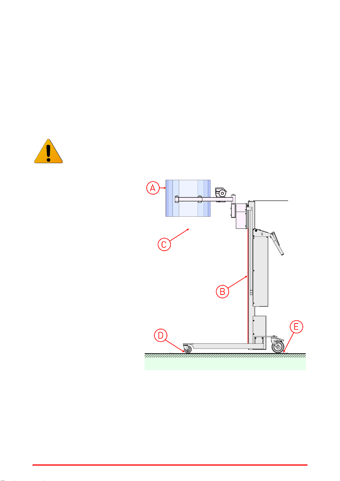
lNo body parts near the sledge or tool at the mast or other lifting equipment when operated
up/down.
lSecure that there is no person below the load, tool and lift when operated.
lThere should be no body parts on top of the front legs steel profile, when the lift is elevated
or operated.
lOnly one person must operate the lift at a time.
lThe user must read and understand these instructions or must have them explained to
them before using the lifter.
lOnly use the lift when operated on a hard-levelled surface during lifting or transporting
loads.
lWhen transporting a cargo, the load should be lowered to the lowest possible position and
secured in order to ensure that the cargo cannot slide.
lAlways secure the cargo on the lift when moving.
lNot in use or storing, always ensure that the sledge is lowered to the lowest possible pos-
ition and is free of any items or cargo.
lOperate and store in a clean, dry location with temperature from +5 °C to +40 °C.
lMake sure that the tool is firmly attached to the sledge and no slack occurs in the bolt con-
nection.
lThe lifter is to be controlled at least once a year or according to laws, regulations, dir-
ectives, working conditions and experience. The control shall be performed by the man-
ufacturer or a skilled technician. Please check your local requirements.
lDo not lift or handle open containers containing corrosive fluids, harmful to people if
spilled.
lIndustrial or commercial use only.
lIndoor use only.
lDo not use the lifter in explosive or flammable hazard environment.
lDo not use or store in a corrosive environment.

8
4 Exception of liability
lHovmand cannot be held responsible for any modifications on the lift or attached equipment, not author-
ized by Hovmand.
lDo only use original spare parts, otherwise Hovmand cannot be held liable for the function and safety of
the lift.
lThe lifter must only be serviced by a qualified technician, otherwise Hovmand cannot be held liable for
the function and safety of the lift.
5 Residual risks
There are residual risks for extraordinary wear, material or product failure due to great impact from col-
lision, misuse, obstacle interference, blockade of driveways, etc.; e.g. a faulty wheel bearing, as a result of
a heavy collision.
Residual risk for personnel working with or around the lifter
A: Do not use the lifter or tool with unstable, unbalanced load.
B: No persons or body parts must be put under or near the tool.
C: Do not put objects or limbs (feet, hands, fingers etc.) into any opening of the lifter or the
tool.
D: Do not put limbs (feet, hands, fingers etc.) in the front wheel.
E: Do not put limbs (feet, hands, fingers etc.) in the back wheel.
Example:
nLoad
nTool
nLifter
nGround

9
6 Operating the lifter
6.1 Remote control - QC3 - 8 buttons
The remote control has 8 buttons, which operate as follows:
The remote control symbols
Button no. / Function Description Symbol Comments
1Lifting The lifter will lift while the button is
pressed ⇧Normal
speed
2Lowering The lifter will lower while the button is
pressed ⇩Normal
speed
3Turning left (counter clockwise) ⟲
4Turning right (clockwise) ⟳
5+6 Manipulator reduces / grips 2 buttons must be pressed at the same
time 1
7+8 Manipulator expands / eases grip-
ping
2 buttons must be pressed at the same
time 2
6.2 Shipping
When shipping the lifter:
lThe sledge must be lowered to the lowest possible position and be free of any items or
cargo.
lFasten the lifter securely during transport.

10
6.3 Safety areas and distance
Safety when operating the tool
The operator must ensure that the tool is clear of obstacles before lifting, lowering or rotating.
The operator must warn other personnel before lifting, lowering, rotating or using the tool.
When lifting, lowering, rotating or using the tool, the operator must:
- stand behind the wheels of the lifter as illustrated below (nA).
- ensure that all other personnel are out of the danger zone as illustrated below(nB).
nLifter
nTool
nSafety area for operator
ASafety distance = 1500 mm
nSafety area for other personnel
Bsafety distance = 3000 mm

11
7 Construction and Materials
All materials are suitable for use in pharma and food industry.
Part Material
Mast Electro polished stainless steel (1.4301 / AISI 304)
Handle Electro polished stainless steel (1.4301 / AISI 304)
Sledge Electro polished stainless steel (1.4301 / AISI 304)
Front cover for mast Electro polished stainless steel (1.4301 / AISI 304)
Remote Polyamide 6
Wheel frame Electro polished stainless steel (1.4301 / AISI 304)
Front wheels Polyurethane
Back wheels Polyamide and Polyurethane

12
8 Batteries and chargers
Before using the batteries
New batteries should always be fully charged prior to using.
Charge the battery pack daily
The battery pack must be charged daily as total discharge can damage the batteries or shorten
their lifespan.
To charge the batteries:
1: Connect the charger to the lifter and the wall-plug.
The indicator changes to green after 1 to 6 hours, which corresponds to 80%
charge.
The battery pack is fit for use as soon as the green light is on.
However, it is recommended to do a full charge, which takes approximately 8
hours.
The charger automatically charges the batteries and switches to maintenance char-
ging when the batteries are fully charged.
Safety when charging
Use only original charger. Check that the wires are in good condition, connect properly and cor-
rect before applying power. Make sure there are no dirt or water in the plug.
The battery status indicator
The lifter is equipped with a battery status indicator, which indicates the battery
status when the lift button is activated.
nRed indicator: Batteries must be recharged immediately.
nOrange indicator: The batteries are functionally charged.
nGreen indicator: The batteries are fully charged.
Safety when discharged
Using discharged batteries means an extreme stress for the battery and should be avoided.

13
9 Lifting equipment
9.1 Quick Clamp with turning unit - QC3
The QC3 consist of a “scissor type” gripping unit and a turning unit.
The QC3 is used to handle items up to 50 kg, which needs to be lifted and turned sideways.
The gripping unit can grip a load and hold it while it is lifted, moved and rotated.
The turning unit can rotate the tool sideways.
QC3 - Quick Clamp with turning unit
Safety
Due to the risk of dropping the load through unintentional pushing a button on the remote con-
trol, the opening and closing functions are operated with two buttons; i.e. both buttons must
be activated simultaneously, in order to perform the desired operation.
There are risks of entrapment hazards, if the safety regulations for using the tools are not
upheld.
The tool, pressure adjustment and grippers, needs to be suitable for handling the specific item.
Do not handle items which you have not specifically made adjustments for, or settings to suit.
Before the turning unit is activated, control that the load is correctly held between the arms of
the tool. This is done by ensuring that all contact areas of the tool are indeed in contact with
the load. Make sure that the load is lifted high enough, so that no collision between the legs,
the floor or other obstacles and the load itself, can occur.
LED indicator
The LED indicator lights up red when the gripping/closing function is activated, and once the tool is gripping
the item with the pre-set holding pressure, the LED indicator turns green.
Adjustments
The gripping pressure needs to be preset in the PLC settings, to suit the item that is handled.
The rotational speed can be adjusted in the PLC settings.
Extra equipment
Different grippers can be mounted on the gripping arms depending on which equipment needs to be
handled; see the separate section on grippers.

14
9.2 Light Indicator
The LED indicator lights red during the Gripping / closing function, when the tool has gripped to the preset
holding pressure, the LED indicator lights green.
9.3 Adjustments
The gripping pressure needs to be preset in the PLC settings, to suit the item that is handled.
The rotational speed can be adjusted in the PLC settings.
9.4 Adjusting speed and Amps for gripping unit
Parameters should only be adjusted by skilled technicians, as
improper procedures may lead to insufficient clamping power
and/or irreversible motor damage.
The following parameters may be adjusted in the control box:
P3: Used for adjusting amps on gripping (clamping force)
P4: Gripping speed
P6: Turning speed

15
10 Maintenance and Inspection
All Hovmand products are designed for minimum maintenance, however some safety checks and pro-
cedures are required.
Hovmand strongly recommends the following checks be carried out on a daily basis and before using the lift.
Ensure that the lift is functioning as intended. If in doubt, do not use.
lThe lifter must be free of dirt or debris which could affect safe operation
lEnsure all labels are present, without damage and are readable.
lEnsure no sign of wear, miss sounds or visual defects.
lEnsure bolts, nuts and rivets should not be loose.
lEnsure correct operation of the brakes.
lEnsure the lifter moves freely on its wheel and the castors.
lEnsure control unit are in working order.
The yearly maintenance must be performed by a qualified technician.
The critical components listed below, must be replaced with the intervals stated, to make sure that the lifter
is in safe, operational condition.
Critical components:
Please contact Hovmand for instruction on how to replace critical components.
Cam belt
lReplace when / if any of the below points occur:
lAny sign of wear, visual cracks, or miscolour.
lUnder normal use (Use < 20 lifts per day, in average over a year), replace after 8 years.
lUnder intensive use (Use > 20 lifts per day, in average over a year), replace after 4 years.
One way bearing
lReplace when / if any of the below points occur:
lAny sign of wear, miss sounds or visual defects.
lUnder normal use (Use < 20 lifts per day in average over a year), replace after 8 years.
lUnder intensive use (Use > 20 lifts per day, in average over a year), replace after 4 years.
11 Disposal
When disposing the lifter, make sure to sort the different materials by category, metal, elec-
tronic waste, batteries etc.. Make sure to follow the local environmental legislations, and hand
over the materials to the local recycling station.
lNote: The batteries contain lead and must be disposed accordingly!

16
12 Cleaning instructions
lSwap batteries
The external battery swap unit must be removed from the lifter, prior to cleaning.
Ingress protection marking (IP)
Model-approved IP code: IP 66 IP code description
Solid particle protection IP 6X Dusttight No ingress of dust; complete protection
against contact (dust tight). A vacuum
must be applied. Test duration of up to 8
hours based on air flow.
Liquid ingress protection IP X6Powerful water
jets
Water projected in powerful jets (12.5mm
nozzle, at a pressure of 100 kPa. at a dis-
tance of 3 m) against the enclosure from
any direction shall have no harmful effects.
Special instructions/Precautions
lAlways wear the correct / appropriate safety equipment.
lLower the lifting tool, so that you don´t risk a head injury when cleaning near the floor.
Detergent application
Use a standard PH neutral
cleaning detergent.
Do not use Acid, Alkaline or harsh chemical
products, these might weaken the drive
belt and other sensitive components or
leave marks on the surfaces.
Work process
lThe outer surfaces can be
cleaned using a wet brush
or a damp cloth.
lThe outer surfaces can be
cleaned using a standard
water hose.
lThe outer surfaces can be
cleaned using a high pres-
sure cleaner; Please note
that the max. allowable
pressure is 100 kPa. at a
distance of 3 m.
lThe lifter must dry for min.
2 hours after cleaning.
Do not use a higher pressure than 100 kPa.
at a distance of 3 m.
Key inspection points
lMake sure the lifter has dried after cleaning.
lThe power connection plug must be completely dry, before mounting the battery unit.
lTest that all functions are working properly before the lifter is taken back into service.

17
13 Resolving faults
Fault type Check the following Solve
The timing belt jumps on
the belt wheel (the belt is
making crackling noises)
Is the belt slack? Tighten the belt using the screws at the
top of the mast.
Is the belt worn? Replace the belt.
The belt is skewed
(the belt squeaks) Is the belt running skewed in the
track on the top cam wheel?
Adjust the screw at the top of the
mast, on the side to which the belt is
skewed.
Is the belt worn? Replace the belt.
The sledge jerks Is there dirt in the mast on which
the sledge runs? Remove the dirt and wipe with alcohol.
Is there dirt on the sledge wheels? Remove the dirt or replace the wheels.
The lifter does not respond Check whether the item being lifted
is heavier than the lift's capacity Remove the item.
Check the main fuse or the on/off
button
Replace the main fuse or press the but-
ton.
Check that the batteries are
charged Connect the charger.
The lift works very slowly Check the voltage of the batteries Connect the charger.
Check the charging frequency. Does
the light quickly change to green
when connected?
If the charger quickly changes to
green, it could indicate that the bat-
teries should be replaced or the fuse on
the charger is broken or the main
switch is off.

18
14 Electrical chart

19
15 Spare parts
15.1 Flexlift INOX mini - Complete
6
14
513
4
11
12
3
10
7
1
2
8
9
ITEM NO.
PART NUMBER
DESCRIPTION
QTY.
1 40010494
Mast INOX 90-3L complete
1
2 30016234
Leg-Box-650x465-75s
1
3 30012062
Adapter plate QC3/-INOX 130
1
4 40010447
Turning Unit max 60kg.
1
5 30012063
Bracket for energy chain QC3
1
6 30012064
Energy belt Impact 130-3L+M
1
7 84290031
Remote control INOX 200 3 function
1
8 30010004
Charger 100-240VAC-24V 1,8A INOX
1
9 30017457
QuickClamp 30-60L
1
10 81010194
Screw M6x16 CS A2 DIN 7991
8
11 81030025
Washer M8 A2 DIN 125 A
4
12 81010233
Screw M8x20 CH A2 DIN 912
4
13 81010315
Screw M4x10 BH A2 ISO 7380
2
14 81010343
Screw M3x6 BH A2 ISO 7380
4
MATERIAL:
Revision: 2
INOX 90-3L Box-650-75ds QC3-Kitchen
6101011277
6101011277
DRAWN BY: LL
WEIGHT: 82.87 Kg
EP
SHEET 2 OF 3
DWG NO.
TITLE:
FINISH:
INOX
30-60L
Date[yy.mm.dd]:
SS
Dimensions:
+/- 5 mm
18.12.04

20
15.2 Mast - Complete
1
10
11
2
12
3
9
6
5
7
8
4
11
ITEM NO.
PART NUMBER
DESCRIPTION
Bom/QTY.
1 40010599
Mast INOX 90-3L
1
284252030
Styring INOX 90-3-QC3A
1
3 84010068
Battery 12V 9AH
4
4 30012922
Handle INOX 90-3
1
5 84040054
Cable Gland M16
1
6 84040055
Nut M16 for Cable Gland
1
7 84030055
Protection cover for charger plug
1
8 84170046
LED Indicator
1
9 30006518
Mounting collar for remote plug
1
10 30006516
Control box cover - INOX 200
1
11 81010466
Screw M5x6 BH A2 ISO 7380
12
12 81010455
Screw M4x8 CH A4 DIN 912
4
13 84020072
Mascot Charger
1
REVISIONS
ZONE
REV.
DESCRIPTION
DATE
APPROVED
- -
See Sheet1
- -
A
B
C
D
E
F
G
H
12345678
A
B
C
D
E
F
G
12345
A2
MATERIAL:
Revision: 2
Mast INOX 90-3L complete
40010494
40010494
DRAWN BY: LL
WEIGHT: 46.93 Kg
EP
SS
SHEET 2 OF 2
1:10
DWG NO.
TITLE:
DO NOT SCALE DRAWING
DEBUR AND
BREAK SHARP
EDGES
FINISH:
UNLESS OTHERWISE SPECIFIED:
DIMENSIONS ARE IN MILLIMETERS
AND WITH TOLERENCES AFTER
DS/ISO 2768-1 MIDDEL
INOX 90
15.06.01
Date[yy.mm.dd]:
Table of contents
Other Varimixer Lifting System manuals
Popular Lifting System manuals by other brands

Genie
Genie CE Series Operator's manual supplement

Haklift
Haklift VAKH6 Translation of the original instructions

REID LIFTING
REID LIFTING PGRS20 Assembly & Operation guide

Reese Explore
Reese Explore 7452700 manual

Bend-Pak
Bend-Pak XPR-10 Series Installation and operation manual

Dino lift
Dino lift 135T operating instructions