manuals.online logo
Brands
  1. Home
  2. •
  3. Brands
  4. •
  5. Vaxcel
  6. •
  7. Lighting Equipment
  8. •
  9. Vaxcel T0478 Instruction manual

Vaxcel T0478 Instruction manual

Other Vaxcel Lighting Equipment manuals

Vaxcel ProLine T0435 Instruction manual

Vaxcel

Vaxcel ProLine T0435 Instruction manual

Vaxcel ProLine T0434 Instruction manual

Vaxcel

Vaxcel ProLine T0434 Instruction manual

Vaxcel T0632 Instruction manual

Vaxcel

Vaxcel T0632 Instruction manual

Vaxcel T0636 Instruction manual

Vaxcel

Vaxcel T0636 Instruction manual

Vaxcel C0213 Instruction manual

Vaxcel

Vaxcel C0213 Instruction manual

Vaxcel T0369 Instruction manual

Vaxcel

Vaxcel T0369 Instruction manual

Vaxcel X0029 Instruction manual

Vaxcel

Vaxcel X0029 Instruction manual

Popular Lighting Equipment manuals by other brands

Life 39.9F70020C quick start guide

Life

Life 39.9F70020C quick start guide

EuroLite LED ML-20 user manual

EuroLite

EuroLite LED ML-20 user manual

LIGMAN OD-50141 installation manual

LIGMAN

LIGMAN OD-50141 installation manual

Home Accents Holiday 1002461144 instructions

Home Accents Holiday

Home Accents Holiday 1002461144 instructions

Experia IRiS Ripple Light instruction manual

Experia

Experia IRiS Ripple Light instruction manual

Erco Gecko Mounting instructions

Erco

Erco Gecko Mounting instructions

Inter-lux ZTA.100.Surface Installation and maintenance instructions

Inter-lux

Inter-lux ZTA.100.Surface Installation and maintenance instructions

Whelen Engineering Company TN Series installation guide

Whelen Engineering Company

Whelen Engineering Company TN Series installation guide

IKEA BJÖRKSPIREA manual

IKEA

IKEA BJÖRKSPIREA manual

Toolland PM 6640 instruction manual

Toolland

Toolland PM 6640 instruction manual

GTD GTD-LP200 user manual

GTD

GTD GTD-LP200 user manual

LIVARNO home 1105-W-UK manual

LIVARNO home

LIVARNO home 1105-W-UK manual

ProLights EclPar IPMFC user manual

ProLights

ProLights EclPar IPMFC user manual

Velvet EVO Series user manual

Velvet

Velvet EVO Series user manual

IDTOLIGHT GENT installation instructions

IDTOLIGHT

IDTOLIGHT GENT installation instructions

MAYTONI S35 installation manual

MAYTONI

MAYTONI S35 installation manual

MaxLite MLFP14DP4535 user manual

MaxLite

MaxLite MLFP14DP4535 user manual

SLV Elektronik 550621 instruction manual

SLV Elektronik

SLV Elektronik 550621 instruction manual

manuals.online logo
manuals.online logoBrands
  • About & Mission
  • Contact us
  • Privacy Policy
  • Terms and Conditions

Copyright 2025 Manuals.Online. All Rights Reserved.

WARNING:
TO AVOID RISK OF ELECTRICAL SHOCK, BE SURE TO SHUT OFF
POWER BEFORE INSTALLING OR SERVICING THIS FIXTURE.
NOTES: 1. Before installing, consult local electrical codes for wiring and grounding requirements.
2. READ AND SAVE THESE INSTRUCTIONS.
ASSEMBLY AND INSTALLATION
INSTRUCTIONS
T0478
Photocell Ball Nut (G)
Fixture
Back Plate
Turn off the power at fuse or circuit box.
Installation Steps
181204
T
IMPORTANT:
The sensor has an excellent photocell function
to enable the light to turn on at dusk and off at
dawn automatically.
Rubber Pad (H)
Bulb Type A
Max.60W
(not include)
Glass Panel
Hardware Package (included):
1. Thread two headless screws (D) through the cross bar (A), and then secure them with four lock nuts (F) (two on each
side of the cross bar (A).) Adjust the length of the headless screws (D) if necessary.
Note: Make sure the headless screws are lined up horizontally to make the fixture level.
Green Grounding Screw (E)
Headless screw (D)
Mounting Screw (B) Wire Connector (C)
Lock Nut (F)
Ball Nut (G) Rubber Pad (H)
Cross Bar (A)
Wire Connector (F)
Outlet Box
Lock Nut (E)
Mounting Screw (B)
Green Grounding Screw (C)
Cross Bar (A)
Fixture
Wire
Fixture Grounding Wire
Headless Screw (D)
Metal Frame
Turn on the power at fuse or circuit box.
181204
1. Turn off the power at the fuse or circuit box before starting installation.
2. Loosen the wire connector connected with the wires from photocell. (See Fig.2)
Note: Do not move the photocell to prevent water from seeping into the outlet box.
3. Take a white pigtail and black pigtail and make wire connections using wire connector (C): (See Fig.3)
a. The black wire from the fixture to one end of the black pigtail.
b. The white wire from the fixture to one end of the white pigtail.
c. The other end of the black pigtail to the black wire from the power source.
d. The other end of the white pigtail to the white wire from the power source.
Put all wires back into the back plate of the fixture.
Operation the Unit Without Photocell
Photocell
White Wires From Photocell
Wire Connector
Wires From Fixture White Pigtail
Red Wires From Photocell
Black wires From Photocell
Fig.2
Wires From Fixture
Wires From
Main Power
Wire Connector (C)
Pigtail
Fig.3
2. Attach the
cross bar
(A) to the outlet box by using two mounting screws (B).
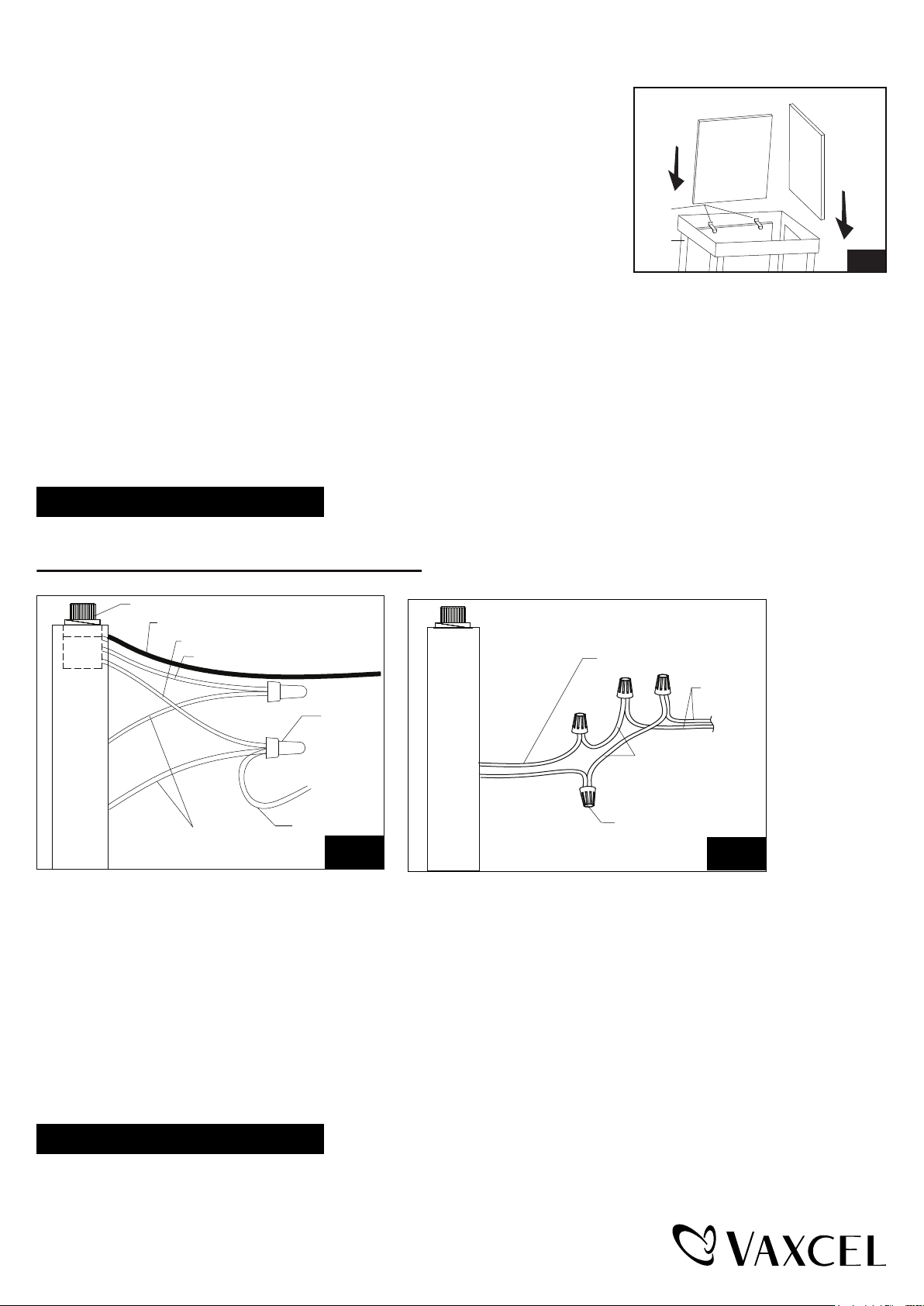
3. Make the bottom of the fixture upward, gently place four glass panels into the metal
frame, then press the clips to secure the glass panels.(Fig.1)
4. Pull out the source wires from the outlet box. Make wire connections using wire
connectors (C) as follows:
---Connect the hot wire (usually black insulation) from the fixture to the black wire
from the power source.
---Connect the neutral wire (usually white insulation) from the fixture to the white
wire from the power source.
---Attach the fixture grounding wire (usually green insulation or bare wire) to the
cross bar
(A) with the green grounding screw (E), and then connect it to the
house grounding wire with the wire connector (C).
Carefully put the wires back into the outlet box.
5. Attach the fixture to the
cross bar
(A) by inserting headless screws (D) into holes on back plate, and then secure it with
two rubber pads (H) and two ball nuts (G).
NOTE: With silicone caulking compound,caulk complete around the back plate meets with the wall surface to
prevent water from seeping into the outlet box.
6. Install a bulb (not included). See relamping label at socket area or packaging for maximum allowed wattage.
Glass Panel
Clip
Metal
Frame Fig.1
181204
The following parts are available for re-order if damaged or missing.
Spare Parts List:
Mounting Hardware
6045MM (1SET)
A
C
B
A: 6-1/4"
B:11-3/4"
C: 7-1/4"
Glass Shade
10065RG (4PCS)
Green Grounding Screw (E)
Headless screw (D)
Mounting Screw (B) Wire Connector (C)
Lock Nut (F)
Ball Nut (G) Rubber Pad (H)
Cross Bar (A)