manuals.online logo
Brands
  1. Home
  2. •
  3. Brands
  4. •
  5. Vaxcel
  6. •
  7. Outdoor Light
  8. •
  9. Vaxcel T0193 Instruction manual

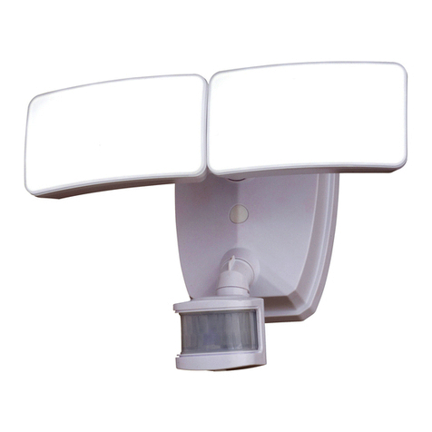
Vaxcel T0193 Instruction manual

Fig.1
Bulb Type A Max.60W
(not included)
Headless
Screw (D)
Side Glass
Panel
Clip Frame
160425
Page 1 / 4
ASSEMBLY AND INSTALLATION
INSTRUCTIONS
T0193 / T0194 / T0195 / T0196
NOTES: 1. Before installing, consult local electrical codes for wiring and grounding requirements.
2. Read and save these instructions.
Features
1. Energy saving fixture.
2. Use the dim-to-bright illumination option where
you want some minimum illumination through out
the night, such as at your front entrance or
garage door. Use the dark-to-bright illumination
option where you do not need minimum
brightness, such as the backyard or back porch.
3. When in manual override mode, use wall switch
to keep the light ON till dawn.
Important to Know
1. Read all instructions carefully before installation and
operation.
2. If you are not familiar with state and local electrical codes,
it is recommended that you consult with a qualified
electrician.
3. Before installation, shut off power at the main fuse or
circuit breaker box. Be aware that simply turning off the
wall switch is not sufficient to prevent an electrical shock.
4. This fixture requires a 120V AC, 60 Hz power source.
5. Do not attempt to take the lantern apart; there are no
serviceable parts inside.
6. To avoid sensor damage by lightning or electrical surge,
make sure the grounding wire is securely connected.
7. For general safety and to avoid any possible damage to
the sensor, be sure the power is switched "off" before
replacing the bulb.
Maximum Wattage: 60W
Work Temperature: -4ºF ~ 104ºF
Hardware Package (included):
Mounting
Screw (B)
Green Grounding
Screw (C)
Lock Nut (F)
Wire Nut (E) Rubber Pad (G) Bolt Nut (H)
WARNING:
TO AVOID RISK OF ELECTRICAL SHOCK, BE SURE TO SHUT OFF
POWER BEFORE INSTALLING OR SERVICING THIS FIXTURE.
T
Cross Bar(A)
Green Grounding Screw (E)
Outlet Box
Wire Nut (F)
Headless Screw (C)
Cross Bar (A)
Mounting Screw (B)
Lock Nut (D)
House Grounding Wire
Fixture Grounding Wire Fixture Wire
Lens
Front Glass
Panel
Side Glass Panel
Socket
Frame
Curve Arm
Finial
Metal Pad
Fixture
Back Plate
Rubber Pad(G)
Bolt Nut(H)
Washer
Set Screw
Hex Nut
160425
Page 2 / 4
1. Thread two headless screws through the cross bar, and then secure them with four lock nuts (two on each side of
the cross bar). Adjust the length of the headless screws if necessary.
Note: Make sure that the headless screws are lined up horizontally to make the fixture level.
2. Attach cross bar to the outlet box using two mounting screws.
3. Make the bottom of the fixture upward, gently place glass panels into the frame, then press the clips to secure the
glass panels. (See Fig.1)
NOTE: The width of the front glass panel is wider than the width of side glass panel .
4. Secure the curved arm to the fixture with metal pad and the finial, and then attach the curved arm to the back plate,
thread the set screw through the holes of curve arm and the back plate, secure them with a washer and a hex nut.
5. Pull out the source wires from the outlet box. Make wire connections using wire nuts as follows:
---Connect the hot wire (usually black insulation) from the power source to the black wire from the fixture.
---Connect the neutral wire (usually white insulation) from the power source to the white wire from the fixture.
---Attach the fixture grounding wire (usually green insulation or bare wire) to the cross bar with the green grounding
screw, or connect to the source grounding wire if available.
Carefully put the wires back into the outlet box.
6. Attach the back plate to the cross bar by inserting the headless screws, and then secure it with two rubber pads and
two bolt nuts.
NOTE: With silicone caulking compound, caulk completely around where the back plate meets with the wall
surface to prevent water from seeping into the outlet box.
7. Install a bulb (not included). Check relamping label at socket area or packaging for maximum allowed wattage.
Installation Steps
Function and Operation
MODES OF OPERATION
Choose a mode by sliding the switch on the bottom of the back plate of the fixture. (See Fig.4 ).
When power is first applied, the light will turn to high level brightness, wait for 15 seconds to allow the sensor to warm up.
1. TEST MODE (daytime and nighttime operation)
● The light will turn to low-level brightness (0%~50% brightness). The light will turn to high-level brightness (100%
brightness) when motion is detected, and stay on as long as the motion is continuing. The light will revert to
low-level brightness about 5 seconds after motion is no longer detected.
2. 3H MODE (nighttime operation only)
●At dusk, the light will turn to high-level brightness (100% brightness). The light will turn to low-level brightness (0%
~50% brightness) automatically after 3 hours. The light will turn to high-level brightness (100% brightness) when
motion is detected, and stay on as long as the motion is continuing. When motion is no longer detected, the light
will remain on for the predetermined time you set (5~180 seconds), and then revert to low-level brightness you set.
● Light will turn off automatically at dawn, and return to 3 H mode at dusk.
3. 6H MODE (nighttime operation only)
●At dusk, the light will turn to high-level brightness (100% brightness). The light will turn to low-level brightness (0%
~50% brightness) automatically after 6 hours. The light will turn to high-level brightness (100% brightness) when
motion is detected, and stay on as long as the motion is continuing. When motion is no longer detected, the light
will remain on for the predetermined time you set (5~180 seconds), and then revert to low-level brightness you set
● Light will turn off automatically at dawn, and return to 6 H mode at dusk.
4. 0 MODE (nighttime operation only)
● The light will turn to low level brightness (0%~50% brightness) at dusk. The light will turn to high-level brightness
(100% brightness) when motion is detected, and stay on as long as the motion is continuing. When motion is no
longer detected, the light will remain on for the predetermined time you set (5~180 seconds), and then revert to
low level brightness you set.
● Light will turn off automatically at dawn, and return to 0 H mode at dusk.
Turn off the power at fuse or circuit box.
Turn on the power at fuse or circuit box.
160425
Page 3 / 4
CUSTOMIZATION OPTIONS:
Shut-off Delay
The Shut-off delay is the length of time the light will stay at high-
level brightness after motion has ceased to be detected. This
Shut-off delay can be set when operation is in 3, 6 or 0 Mode by
using the “TIME” knob located on the left side of the panel at the
bottom of the back plate (See Fig.4) . To increase the shut-off
delay, turn the knob clockwise. To decrease shut off delay, turn
the knob counterclockwise. The delay may be adjusted from a minimum of 5 seconds to a maximum of 3 minutes. The
light will stay on as long as motion is detected continuously and will automatically turn to low-level brightness when no
more motion is detected after the delay time has passed.
Sensitivity of Motion Sensor
The sensitivity of the motion sensor can be adjusted by using the “SENSITIVITY” knob located on the right side of the
panel at the bottom of the back plate (See Fig.4). To increase sensitivity, turn the knob clockwise. To decrease
sensitivity, turn the knob counterclockwise. The sensitivity may be adjusted from a minimum of 5 feet to a maximum of
35 feet.
NOTE:
1. The sensitivity of the motion sensor will increase as the
environmental temperature gets cooler. For best
performance, gently clean the lens with a soft cloth every
1 or 2 months to assure maximum sensitivity.
2. For best performance, install fixture at least 6 feet above
the ground. At such a height, the fixture will provide a
detection distance of up to 35 feet at 77 degrees
Fahrenheit. (See Fig.5)
3. The sensor detects across a detection range of 120 degrees.
(See Fig.6)
4. The sensor will be more sensitive to motion across its
detection path than motion directly towards it. (See Fig.7)
5. To reduce possible nuisances, do not mount the fixture
near a heat source like an air conditioner, vent or furnace
exhaust, or in a direction facing any reflecting object or
other light source.
Motion
Least sensitive
Motion
Most sensitive
Sensor
(Adjustable low level)
(View from one side of Back plate)
Fig.3
Fig.6
Fig.5
Fig.7
“3H Mode”
“6H Mode”
“0 Mode”
Manual
Override
Mode
Turn wall switch OFF-ON
in 3 Seconds
Turn wall switch OFF-ON
in 3 Seconds again
Fig.2
Manual Override Operation Diagram
(View from Bottom of Back plate)
(Exterior Wall)
TIME SENSITIVITY
TEST 0
3 6
Fig.4
5.Manual Override MODE (nighttime operation only; on at dusk,off at dawn)
● In 3, 6 or 0 mode, to shift to manual override mode, turn off the wall switch in 3 seconds and then turn it on
again, the light will turn to high-level brightness at dusk, and turn off automatically at dawn. To return to the
previous settings, turn off the wall switch in 3 seconds and then turn it on again. (See Fig.2)
● The lights will turn off automatically at dawn.
Note:You can adjust the low level brightness (0~50%) by using the slide switch on the side of back plate.
(See Fig.3)
5'
8.0'
6.5'
35'
Where you install your lantern is important:
Be sure the light is mounted straight on the wall;
otherwise, the detection distance may be limited.
120°
Page 4 / 4
160425
Troubleshooting
---If the light does not work at all:
1. Make sure the wall switch and circuit breaker are on.
2. Make sure the wiring connection is correct.
3. Make sure the bulb is not burned out.
4. Cover the sensor with your palm to verify that the ambient light level is not too high.
----In Test Mode, if the light stays on full brightness after 5 seconds:
1. Check whether the motion is detected at all time.
----After performing 3H or 6H mode, or in 0 H mode. If the light stays on full brightness after 3 minutes.
1. Make sure no motion could be picked up by the sensor.
2. Make sure that mode entry is not in manual override.
----In PC / Manual override Mode, if the light stays on after dawn:
1. Whether the ambient light level is too low.
----If the light blinks:
1. Make sure the light is not mounted near a barbecue, air conditioner or other heat source.
2. Make sure of using incandescent bulb or dimmable LED bulb.
The following parts are available for re-order if damaged or missing.
Spare Parts List:
Assembly Kit
5551MM (1 SET) FOR T0193, T0195
5552MM (1 SET) FOR T0194, T0196
Mounting
Screw (B)
Glass Panel
9813CS (1 SET) FOR T0193, T0194
Glass Panel
9814CS (1 SET) FOR T0195, T0196
Green Grounding
Screw (C)
Lock Nut (F)
Wire Nut (E) Rubber Pad (G)
Headless
Screw (D)
Bolt Nut (H)
T0193 T0194
A: 10" B: 19" C: 11"
T0195 T0196
A: 7" B: 14-1/2" C: 7-5/8"
5-YEAR LIMITED WARRANTY:
All products are warranted to be free of defects in material and workmanship for five (5) years from date of
purchase. This warranty is limited to the correction of any such defect, or the replacement of any such defective
item(s), provided that: (a) we are properly notified and consent to return of the item(s) in question:(b) the item(s)
is / are returned with proof of purchase date; and (c) it is found upon inspection by us that the item(s) is / are defective
as noted above. This warranty does not cover labor costs, consequential damages, nor does it apply to any item(s) that
have been improperly installed, overloaded, altered, or otherwise abused by the customer, its agent(s) or employee(s).
Finishes are specially excluded from the terms of this warranty since they are subject to environmental maintenance
deemed beyond our control. Other than the described obligation, we assume no further liability with respect to the sale
or use of our products.We make no warranty, express or implied, and disclaim any warranty of merchantability or fitness
for a particular purpose.
Cross Bar(A)

This manual suits for next models

3

Other Vaxcel Outdoor Light manuals

Vaxcel T0395 Instruction manual

Vaxcel

Vaxcel T0395 Instruction manual

Vaxcel T0626 Instruction manual

Vaxcel

Vaxcel T0626 Instruction manual

Vaxcel T0365 Instruction manual

Vaxcel

Vaxcel T0365 Instruction manual

Vaxcel T0568 Instruction manual

Vaxcel

Vaxcel T0568 Instruction manual

Vaxcel Theta T0612 Instruction manual

Vaxcel

Vaxcel Theta T0612 Instruction manual

Vaxcel T0294 Instruction manual

Vaxcel

Vaxcel T0294 Instruction manual

Vaxcel T0698 Instruction manual

Vaxcel

Vaxcel T0698 Instruction manual

Vaxcel T0199 Instruction manual

Vaxcel

Vaxcel T0199 Instruction manual

Vaxcel T0362 Instruction manual

Vaxcel

Vaxcel T0362 Instruction manual

Vaxcel T0616 Instruction manual

Vaxcel

Vaxcel T0616 Instruction manual

Vaxcel T0717 Instruction manual

Vaxcel

Vaxcel T0717 Instruction manual

Vaxcel T0244 Instruction manual

Vaxcel

Vaxcel T0244 Instruction manual

Vaxcel T0696 Instruction manual

Vaxcel

Vaxcel T0696 Instruction manual

Vaxcel T0366 Instruction manual

Vaxcel

Vaxcel T0366 Instruction manual

Vaxcel T0435 Instruction manual

Vaxcel

Vaxcel T0435 Instruction manual

Vaxcel T0414 Instruction manual

Vaxcel

Vaxcel T0414 Instruction manual

Vaxcel T0080 Instruction manual

Vaxcel

Vaxcel T0080 Instruction manual

Vaxcel T0274 Instruction manual

Vaxcel

Vaxcel T0274 Instruction manual

Vaxcel T0396 Instruction manual

Vaxcel

Vaxcel T0396 Instruction manual

Vaxcel T0451 Instruction manual

Vaxcel

Vaxcel T0451 Instruction manual

Vaxcel T0696 Instruction manual

Vaxcel

Vaxcel T0696 Instruction manual

Vaxcel T0701 Instruction manual

Vaxcel

Vaxcel T0701 Instruction manual

Vaxcel T0321 Instruction manual

Vaxcel

Vaxcel T0321 Instruction manual

Vaxcel T0595 Instruction manual

Vaxcel

Vaxcel T0595 Instruction manual

Popular Outdoor Light manuals by other brands

ring Spotlight manual

ring

ring Spotlight manual

HEPER NORMA LB6055.510-US Installation & maintenance instructions

HEPER

HEPER NORMA LB6055.510-US Installation & maintenance instructions

LIGMAN GA-31911 installation manual

LIGMAN

LIGMAN GA-31911 installation manual

Clas Ohlson ZK8054 instruction manual

Clas Ohlson

Clas Ohlson ZK8054 instruction manual

LIGMAN OD-50001 installation manual

LIGMAN

LIGMAN OD-50001 installation manual

Sistemalux MEGAZIP S8500 instruction sheet

Sistemalux

Sistemalux MEGAZIP S8500 instruction sheet

Modern Forms WS-W68618 Installation instruction

Modern Forms

Modern Forms WS-W68618 Installation instruction

Hubbardton Forge Edge 302560 Assembly/installation instructions

Hubbardton Forge

Hubbardton Forge Edge 302560 Assembly/installation instructions

IKEA SOLVINDEN manual

IKEA

IKEA SOLVINDEN manual

Konyks Antalya Easy E27 quick start

Konyks

Konyks Antalya Easy E27 quick start

Paradise Datacom U000-0880 instructions

Paradise Datacom

Paradise Datacom U000-0880 instructions

RAB Lighting WP4 Series installation instructions

RAB Lighting

RAB Lighting WP4 Series installation instructions

Cameo F2 D IP user manual

Cameo

Cameo F2 D IP user manual

Pilz PIT si1.2 operating instructions

Pilz

Pilz PIT si1.2 operating instructions

Endon Burford instruction manual

Endon

Endon Burford instruction manual

Ingo Maurer The MaMo Nouchies Samurai Mounting instructions

Ingo Maurer

Ingo Maurer The MaMo Nouchies Samurai Mounting instructions

Quoizel PRV8408K Assembly instruction

Quoizel

Quoizel PRV8408K Assembly instruction

Maxim 3044RPOLB installation instructions

Maxim

Maxim 3044RPOLB installation instructions

manuals.online logo
manuals.online logoBrands
  • About & Mission
  • Contact us
  • Privacy Policy
  • Terms and Conditions

Copyright 2025 Manuals.Online. All Rights Reserved.