manuals.online logo
Brands
  1. Home
  2. •
  3. Brands
  4. •
  5. Vaxcel
  6. •
  7. Outdoor Light
  8. •
  9. Vaxcel T0626 Instruction manual

Vaxcel T0626 Instruction manual

Page 1 / 4
211221
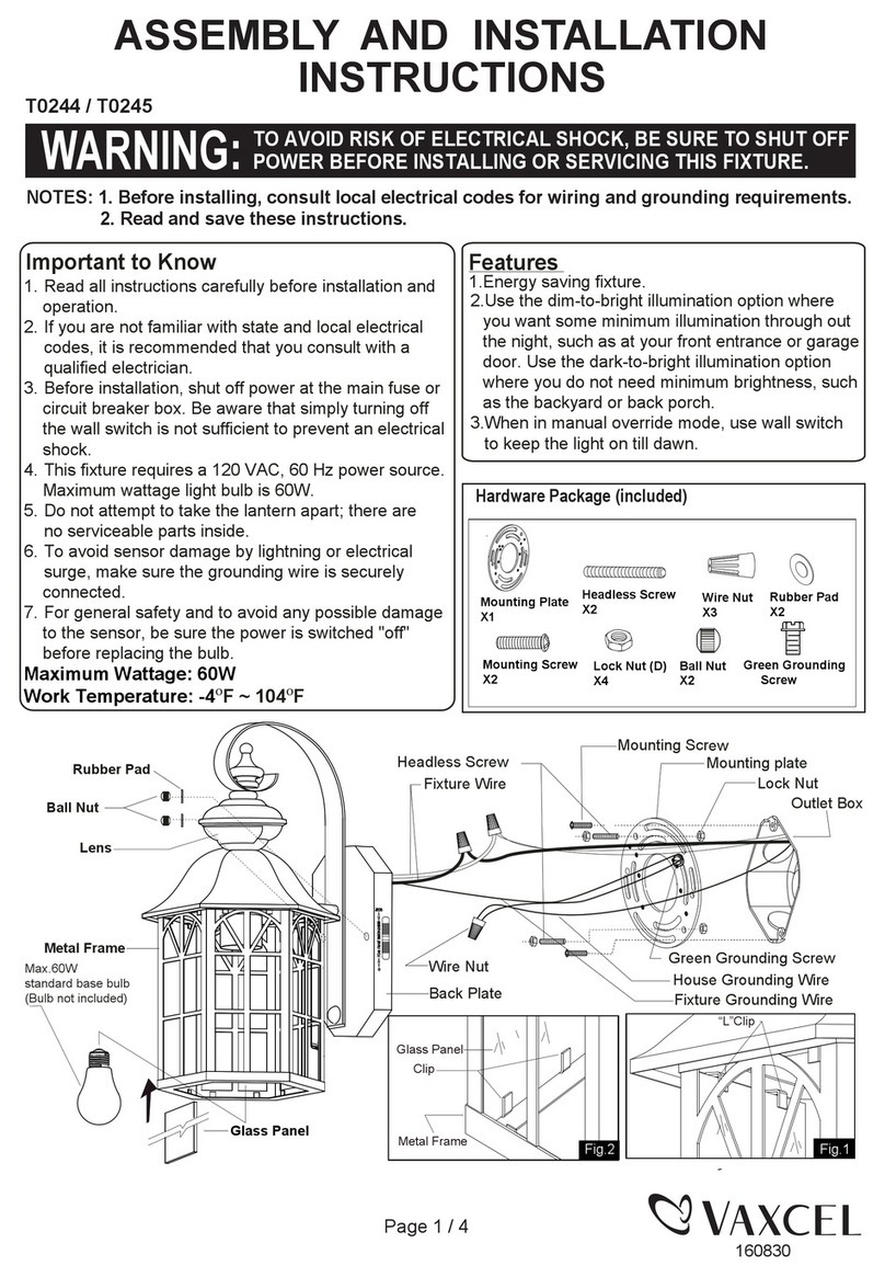
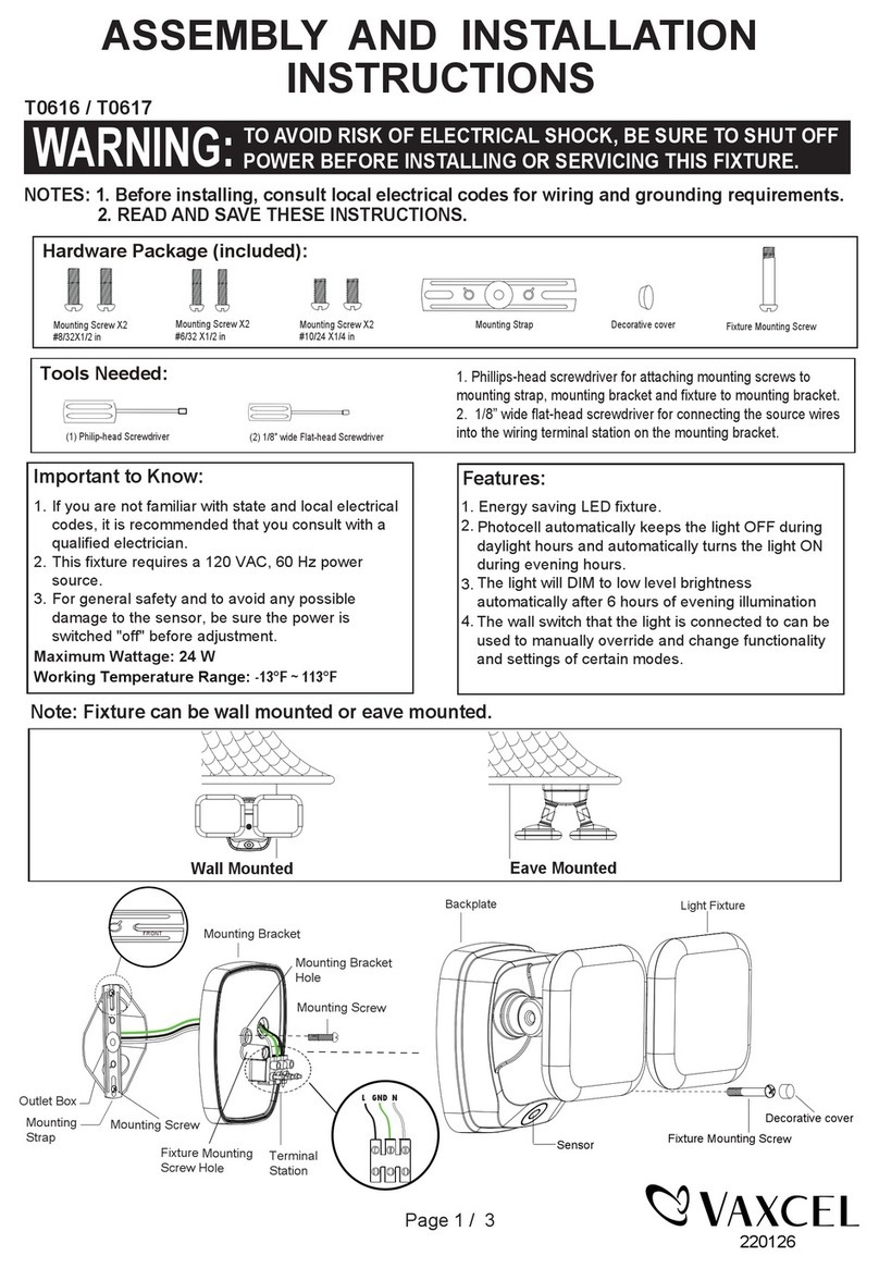
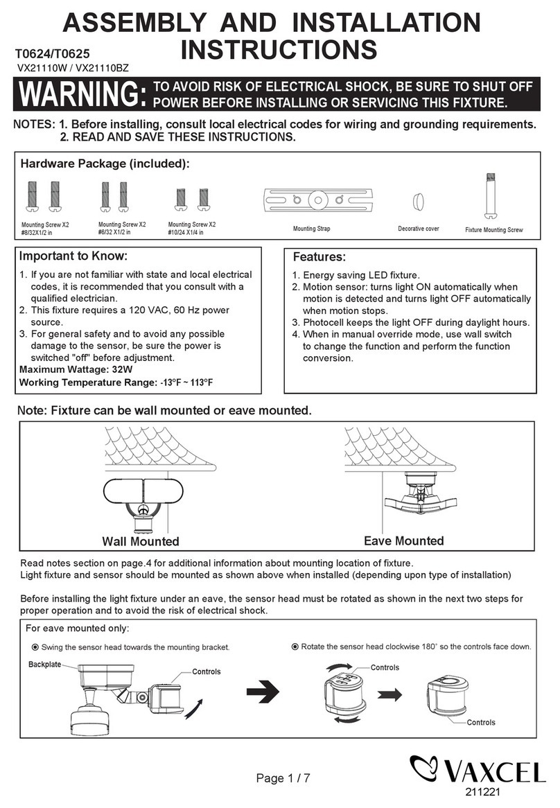
Important to Know:
1. If you are not familiar with state and local electrical
codes, it is recommended that you consult with a
qualified electrician.
2. This fixture requires a 120 VAC, 60 Hz power
source.
3. For general safety and to avoid any possible
damage to the sensor, be sure the power is
switched "off" before adjustment.
Maximum Wattage: 32 W
Working Temperature Range: -13°F ~ 113°F
ASSEMBLY AND INSTALLATION
INSTRUCTIONS
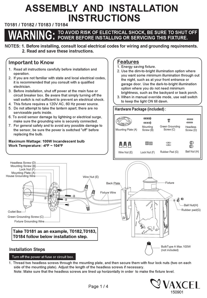
NOTES: 1. Before installing, consult local electrical codes for wiring and grounding requirements.
2. READ AND SAVE THESE INSTRUCTIONS.
T0626/T0627
Features:
WARNING:
TO AVOID RISK OF ELECTRICAL SHOCK, BE SURE TO SHUT OFF
POWER BEFORE INSTALLING OR SERVICING THIS FIXTURE.
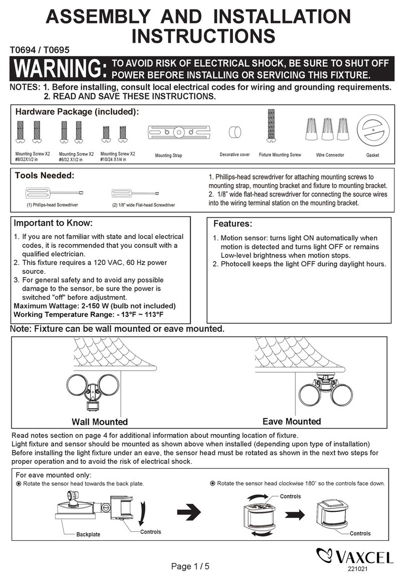
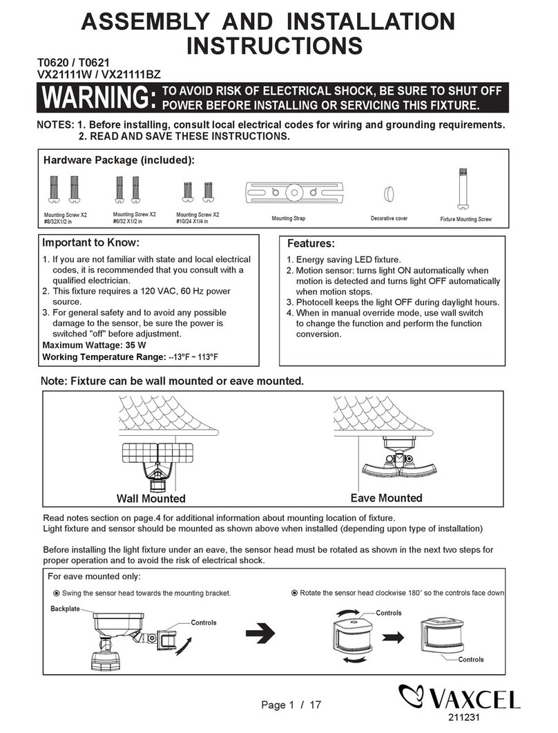
Note: Fixture can be wall mounted or eave mounted.
Wall Mounted Eave Mounted
1. Energy saving LED fixture.
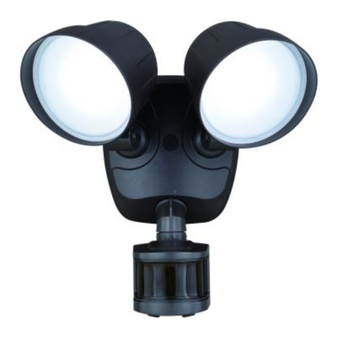
2. Motion sensor: turns light ON automatically when
motion is detected and turns light OFF automatically
when motion stops.
3. Photocell keeps the light OFF during daylight hours.
4. When in manual override mode, use wall switch
to change the function and perform the function
conversion.
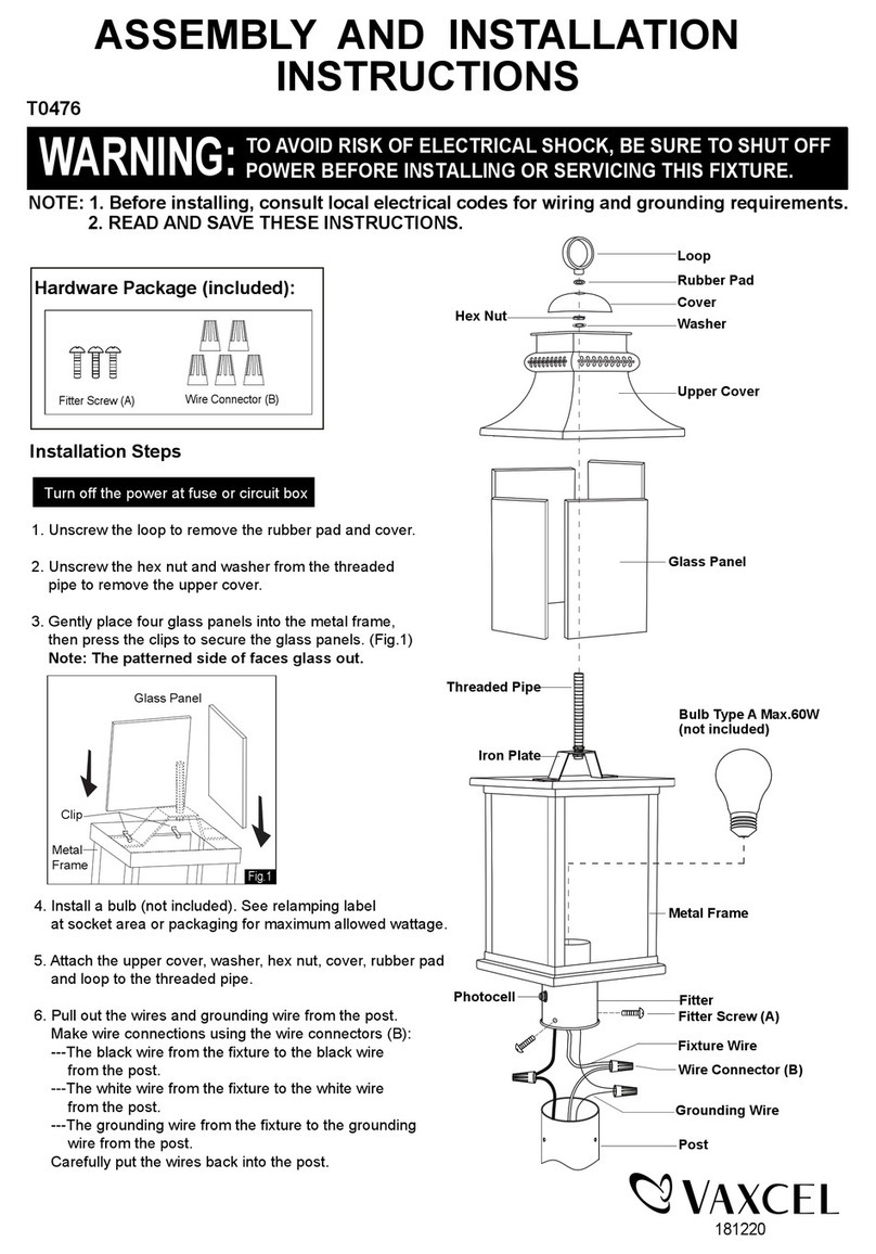
Hardware Package (included):
Mounting Screw X2
#8/32X1/2 in Fixture Mounting Screw
Mounting Strap Wire Connector X3
Mounting Screw X2
#6/32 X1/2 in
Mounting Screw X2
#10/24 X1/4 in Decorative cover
Sensor
Backplate Light Fixture
Fixture Mounting Screw
Decorative cover
Mounting Bracket
Mounting Strap
Outlet Box
Mounting Screw
FRONT
VX21301W / VX21301BZ
Choose a mode by rotating the switch on the bottom of the sensor of the fixture. (See Fig.4)
Note: When power is first applied, the light will be on and warm up lasts 30 seconds.
1. Switch Control Mode (No network,No Linkage)
● In "Switch Control"Mode,the light turn on 100% brightness and pre-selected CCT color(2700K~5000K).
● In "Switch Control"Mode,turn the wall switch “OFF" then turn it "ON" twice within 3 seconds,the light switch 100%
brightness to 30% brightness and pre-selected CCT color(2700k~5000k).To shift back 100% brightness ,turn on
"OFF" and "ON" within 3 seconds again.
● Power off for 5 seconds,then turn on the light,which will return to 100% brightness.
2. Motion Link Mode
● In "Motion Link" Mode,the light will be on 30% brightness and 2700k CCT color.
When the light receive the motion signal: In daytine,the Motion light will turn off due to the Photo sensor, and also
send a signal to motion link mode light for turning off.
Dusk Early Evening: Receive Motion Light signal and turn on the light (Low Level 30% 2700K CCT).
Motion Detection: Receive Motion Light signal and turn on the light (High Levek 100% 5000K CCT).
Dawn Morning: Receive Motion Light signal and turn off the light (perform same as motion light).
3. Not Link
● Press and hold the Link button on the body of light for 3 seconds,the light will flash 3 times to exit linkage.
● In RF Link State,shift the switch from Motion Link Mode to Switch Control Mode,the light will return to Switch
Control function.
Page 2 / 4
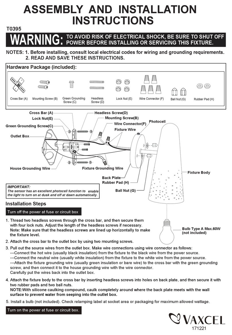
Installation Steps
Turn off the power at fuse or circuit box.
Turn on the power at the main fuse or circuit breaker box.
Adjusting the Light Head:
1. Gently grasp the light heads and tilt them up or down, left or right to
adjust the light coverage area. Keep the light heads at least 1˝ (25mm)
away from the sensor.(See Fig. 4)
2. Keep the light heads 30˚ below horizontal to avoid water damage and
electrical shock.
Fig. 4
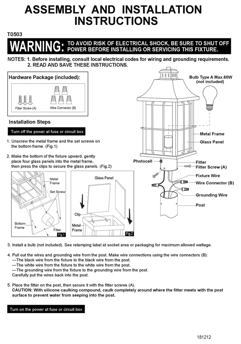
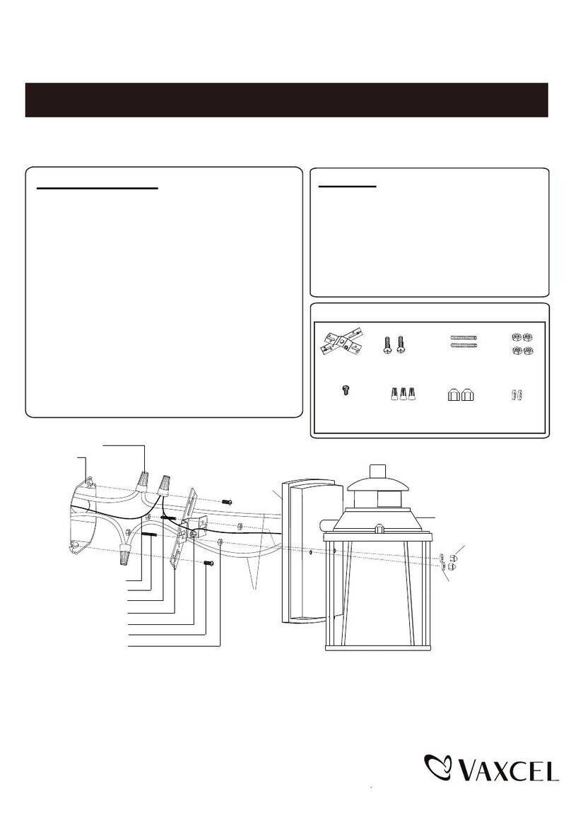
1. The fixture mounting bracket is pre-assembled on the light fixture. Unscrew both the decorative cover and the fixture
mounting screw in order to remove the mounting bracket.
2. Install the mounting strap to the outlet box with the stamped word “FRONT” facing away from the outlet box, using two
mounting screws that best fit the outlet box. Mounting bracket should sit flush against wall surface when secured.
(Choose one matching pair of suitable mounting screws from the 3 pairs provided).
3. Pull out the source wires from the outlet box.Connect the black wire from the outlet box to the "L" interface of the
terminal station on the mounting bracket. Connect the white wire from the outlet box to the "N" interface of the terminal
station on the mounting bracket. Carefully tuck the wires back into the outlet box.
4. Place mounting bracket against the outlet box, insert the mounting bracket screw through the mounting bracket hole,
thread mounting bracket screw into the center hole of the mounting strap. Tighten the mounting bracket screw securely.
5. Attach the backplate of the light fixture to the mounting fixture mounting screw. Then push the decorative cover firmly
into the fixture mounting screw hole on the light fixture.
6. With silicone caulking compound, caulk completely around where the back plate meets the wall surface.
CAUTION: Be sure to caulk completely where the back plate meets the wall surface to prevent water from
seeping into the outlet box.
211221
4. RF Linking Network Setup
From all the light units, select one as the main unit and the others as the sub-units;
First to setup all the sub-units by press the Link button twice within 3 seconds, the sub-units will flash once every 1
second meaning it is waiting to receive matching signal from the main light.
Then to setup the main unit by press and hold the Link button for 5 seconds, the main unit will flash slowly
(once every 3 seconds), and when the sub-units have paired with the signal, the sub-units will stop flashing
confirming it have paired with the main unit. (if pairing not successful, the sub-unit will keep flashing).
When all the sub-units have stop flashing, press the Link button on the main unit once to complete the pairing process.
(the main unit will stop flashing)
After complete the pairing process, any light within the Link group range can send or receive the photo sensor or
motion sensor signal from the other light and response accordingly.
Note: Maximum link up to 10 units per link group, each light can link within 120ft apart.
5. Unlink the unit from the Link Group
Press and hold the Link button on the sensor head for 3 seconds, the light will flash 3 times to confirm reset and remove
from the Link Group.
All lights will need to be reset before setup the Link Group. Strongly recommended to set all the linked lights to the
same MODE to avoid any confusion of function error.
Manual Override
6. Switch Control Mode
● In"Swich Control"Mode,turn the wall switch “OFF" then turn it "ON" twice
within 3 seconds,the light switch 100% brightness to 30% brightness and
pre-selected CCT color(2700k~5000k).To shift back 100% brightness,
turn on"OFF" and "ON" within 3 seconds again.
Power off for 5 seconds,then turn on the light,which will return to 100%
brightness and pre-selected CCT color.
7. Motion Link Mode
● In "Motion Link Mode"and Linkage state, turn the wall switch "OFF",then turn it “ON" twice within 3 seconds,the light
will stop to receive sensor signal and photo senosr signal of other lights and be on 100% brightness and pre-selected
CCT color(2700K~5000K).Turn off and on the lgiht by ON/OFF switch.
● To shift back the linkage state,turn the wall switch "OFF" and "ON" twice within 3 seconds again,the light will be on
30% brightness and 2700K CCT color. Before RF Linkage,turn the wall switch "OFF" and "ON" twice within 3 seconds,
the light will be on 100% brightness and pre-selected CCT color(2700K~5000K).
Page 3 / 4
211221
Troubleshooting
---The light does not come on at all:
1. Make sure the wall switch and circuit breaker are on.
2. Make sure the wiring is correct.
3. Cover the sensor with dark color cloth to verify that the ambient light level is not too high.
---The light comes on for no apparent reason
1. Re-aim the motion sensor.
2. Decrease the sensitivity setting.
3. Do not use a dimmer or timer to control the light fixture. Replace the dimmer or timer with a standard on/off wall.
---The light flashes on and off:
1. Reposition the bulb away from the motion sensor.
2. Reposition the motion sensor.
3. The motion sensor is in “TEST” mode and warm up.
Mounting Screw X2
#8/32X1/2 in Fixture Mounting Screw
Mounting Strap
Mounting Screw X2
#6/32 X1/2 in
Mounting Screw X2
#10/24 X1/4 in Decorative cover
Assembly Kit
6466MM (1 SET)
The following parts are available for re-order if damaged or missing. Call our toll free at 1-800-887-6326.
Fig.5
2700K 5000K
Motion
Link
Switch
Control
CCT MODE
211221
Page 4 / 4
5-YEAR LIMITED WARRANTY:
All products are warranted to be free of defects in material and workmanship for five (5) years from date of purchase.
This warranty is limited to the correction of any such defect, or the replacement of any such defective item(s), provided
that: (a) we are properly notified and consent to return of the item(s) in question:(b) the item(s) is / are returned with proof
of purchase date; and (c) it is found upon inspection by us that the item(s) is / are defective as noted above. This warranty
does not cover labor costs, consequential damages, nor does it apply to any item(s) that have been improperly installed,
overloaded, altered, or otherwise abused by the customer, its agent(s) or employee(s). Finishes are specially excluded
from the terms of this warranty since they are subject to environmental maintenance deemed beyond our control. Other
than the described obligation, we assume no further liability with respect to the sale or use of our products.We make no
warranty, express or implied, and disclaim any warranty of merchantability or fitness for a particular purpose.
B
A
C
A: 5-1/4"
B:10-1/4"
C: 6"
FCC Statement
This device complies with Part 15of the FCC Rules. Operation is subject to the following two conditions:
(1) this device may not cause harmful interference, and (2) this device must accept any interference received,
including interference that may cause undesired operation.
Changes or modifications to this unit not expressly approved by the party responsible for compliance could void
the user’s authority to operate the equipment.
NOTE: This equipment has been tested and found to comply with the limits for a Class B digital device, pursuant to
Part 15 of the FCC Rules. These limits are designed to provide reasonable protection against harmful interference
in a residential installation. This equipment generates uses and can radiate radio frequency energy and, if not
installed and used in accordance with the instructions, may cause harmful interference to radio communications.
However, there is no guarantee that interference will not occur in a particular installation. If this equipment does
cause harmful interference to radio or television reception, which can be determined by turning the equipment off
and on, the user is encouraged to try to correct the interference by one or more of the following measures:
Reorient or relocate the receiving antenna.
Increase the separation between the equipment and receiver.
Connect the equipment into an outlet on a circuit different from that to which the receiver is connected.
Consult the dealer or an experienced radio/TV technician for help.

This manual suits for next models

3

Other Vaxcel Outdoor Light manuals

Vaxcel T0238 Instruction manual

Vaxcel

Vaxcel T0238 Instruction manual

Vaxcel T0142 Instruction manual

Vaxcel

Vaxcel T0142 Instruction manual

Vaxcel T0366 Instruction manual

Vaxcel

Vaxcel T0366 Instruction manual

Vaxcel T0414 Instruction manual

Vaxcel

Vaxcel T0414 Instruction manual

Vaxcel T0103 Instruction manual

Vaxcel

Vaxcel T0103 Instruction manual

Vaxcel T0396 Instruction manual

Vaxcel

Vaxcel T0396 Instruction manual

Vaxcel T0449 Instruction manual

Vaxcel

Vaxcel T0449 Instruction manual

Vaxcel T0451 Instruction manual

Vaxcel

Vaxcel T0451 Instruction manual

Vaxcel T0165 Instruction manual

Vaxcel

Vaxcel T0165 Instruction manual

Vaxcel T0698 Instruction manual

Vaxcel

Vaxcel T0698 Instruction manual

Vaxcel T0389 Instruction manual

Vaxcel

Vaxcel T0389 Instruction manual

Vaxcel T0040 Instruction manual

Vaxcel

Vaxcel T0040 Instruction manual

Vaxcel Proline T0429 Instruction manual

Vaxcel

Vaxcel Proline T0429 Instruction manual

Vaxcel T0551 Instruction manual

Vaxcel

Vaxcel T0551 Instruction manual

Vaxcel T0694 Instruction manual

Vaxcel

Vaxcel T0694 Instruction manual

Vaxcel T0694 Instruction manual

Vaxcel

Vaxcel T0694 Instruction manual

Vaxcel Chatham Instruction manual

Vaxcel

Vaxcel Chatham Instruction manual

Vaxcel T0503 Instruction manual

Vaxcel

Vaxcel T0503 Instruction manual

Vaxcel T0076 Instruction manual

Vaxcel

Vaxcel T0076 Instruction manual

Vaxcel T0062 Instruction manual

Vaxcel

Vaxcel T0062 Instruction manual

Vaxcel T0541 Instruction manual

Vaxcel

Vaxcel T0541 Instruction manual

Vaxcel T0517 Instruction manual

Vaxcel

Vaxcel T0517 Instruction manual

Vaxcel T0099 Instruction manual

Vaxcel

Vaxcel T0099 Instruction manual

Vaxcel T0297 Instruction manual

Vaxcel

Vaxcel T0297 Instruction manual

Popular Outdoor Light manuals by other brands

LIGMAN LA-60014 installation manual

LIGMAN

LIGMAN LA-60014 installation manual

SUN AMEX STELLAR Instructions for use

SUN AMEX

SUN AMEX STELLAR Instructions for use

ANSMANN WORKLIGHT WL250B SLIM manual

ANSMANN

ANSMANN WORKLIGHT WL250B SLIM manual

Timberlab Punto manual

Timberlab

Timberlab Punto manual

LIGMAN NORDSTROM 3 NOD-50021 installation manual

LIGMAN

LIGMAN NORDSTROM 3 NOD-50021 installation manual

Lunux HELLUX 162-5 DB instruction manual

Lunux

Lunux HELLUX 162-5 DB instruction manual

STEINEL XLED home 2 SL Information

STEINEL

STEINEL XLED home 2 SL Information

Ecco EW2015R Installation and operation instructions

Ecco

Ecco EW2015R Installation and operation instructions

B-K lighting EC Safety and installation instructions

B-K lighting

B-K lighting EC Safety and installation instructions

Saxby Lighting Severus Instruction leaflet

Saxby Lighting

Saxby Lighting Severus Instruction leaflet

Faro Barcelona BOLETUS instructions

Faro Barcelona

Faro Barcelona BOLETUS instructions

Silverwood CPLF1267E Assembly instructions

Silverwood

Silverwood CPLF1267E Assembly instructions

MOOD AYANA Installation Notice

MOOD

MOOD AYANA Installation Notice

MELINERA 327429-1904 Operation and safety notes

MELINERA

MELINERA 327429-1904 Operation and safety notes

GEV FRIEDA 2432 manual

GEV

GEV FRIEDA 2432 manual

Viso Systems REF800 user manual

Viso Systems

Viso Systems REF800 user manual

JONATHAN Y JYL6104A manual

JONATHAN Y

JONATHAN Y JYL6104A manual

LIGMAN FUN-50032 installation manual

LIGMAN

LIGMAN FUN-50032 installation manual

manuals.online logo
manuals.online logoBrands
  • About & Mission
  • Contact us
  • Privacy Policy
  • Terms and Conditions

Copyright 2025 Manuals.Online. All Rights Reserved.