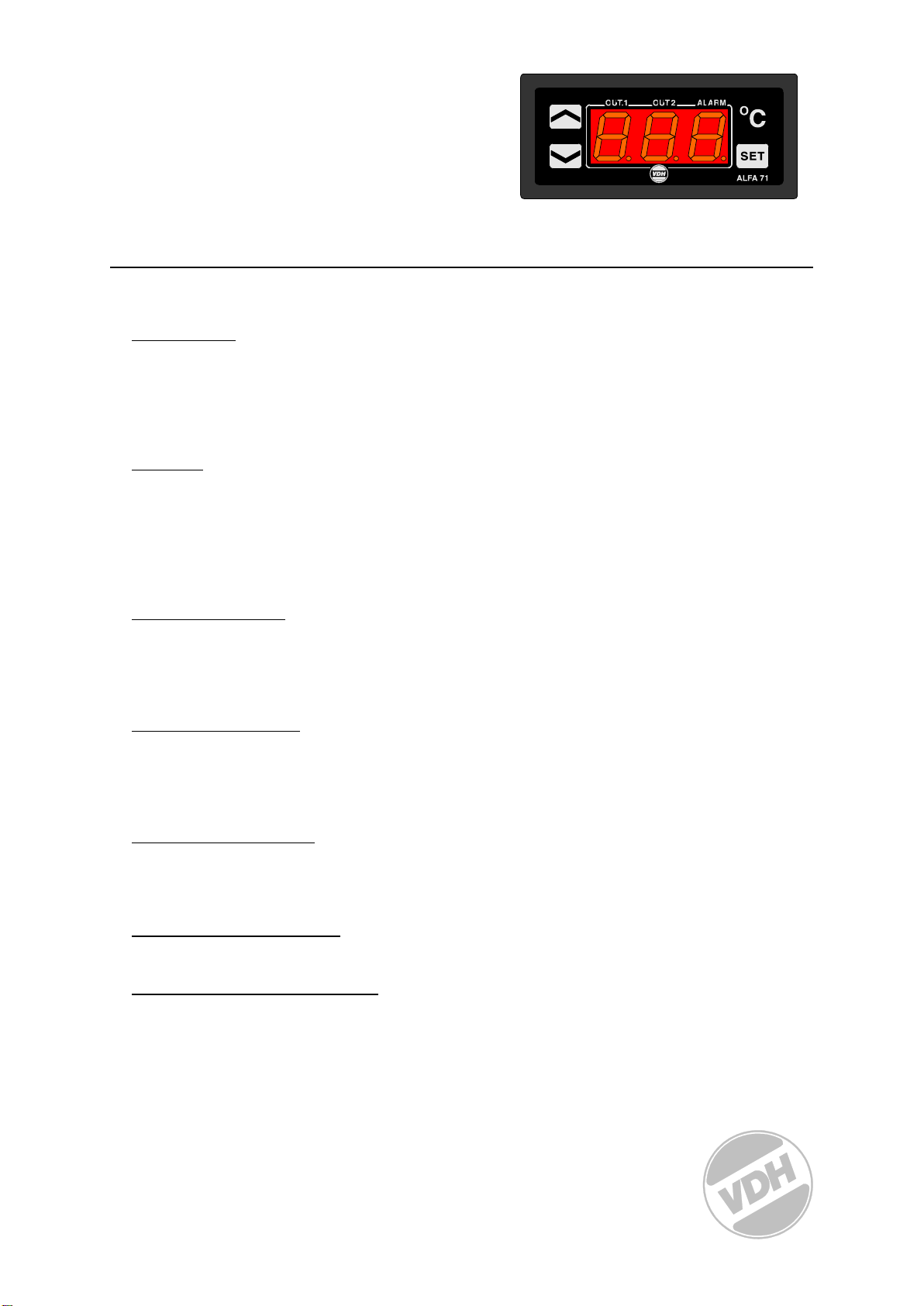
manuals.online logo
Brands
  1. Home
  2. •
  3. Brands
  4. •
  5. VDH
  6. •
  7. Thermostat
  8. •
  9. VDH ALFA 71 MOD User manual

VDH ALFA 71 MOD User manual

1
User manual
ALFA 71 MODulation
Thermostat.
VDH doc. 052939 Version: v1.0 Date: 03-10-2005
Software: ALFA71MOD File: DO052939.WPD Range: -50/+50,0C
*Installation.
On the top side of the ALFA 71 MOD is shown how the sensors, power supply, relays and 0..10Vdc
PI output has to be connected.
After connecting the ALFA 71 MOD to the power supply, a self test function is started. As this test is
finished the measured temperature appears in the display.
*Control.
The ALFA 71 MOD thermostat can be controlled by four pushbuttons on the front. These keys are:
SET - view / change the setpoint.
UP - increase the setpoint.
DOWN - decrease the setpoint.
C- hidden push button above the SET key and behind Csymbol.
*Viewing setpoint.
By pushing the SET key the setpoint appears in the display. The decimal point of the last display
starts blinking. A few seconds after releasing the SET key the setpoint disappears and the
measured temperature is shown again in the display.
*Changing setpoint.
Push the SET key and the setpoint appears in the display. Release the SET key. Now push the SET
keyagain together with the UP or DOWN keys to change the setpoint. A few seconds after
releasing the keys the measured temperature shows again in the display.
*Status of the Relays.
By pushing the hidden Ckey the display shows the status of the relays. Each display segment
shows the status of the relay output, showing 0=off and 1=on. The code 110 means relay 1 and 2
are on and relay 3 is off.
*Readout valve position.
By pushing the UP key the display shows the current valve position.
*Setting internal parameters.
Next to the adjustment of the setpoint, internal settings can be made like differential, sensor-offset,
setpoint range and the functions of the thermostat.
Push the DOWN key more than 10 seconds, to enter the 'Internal Programming Menu'. In the left
display the upper and lower segment are blinking. Over the UP and DOWN keys the required
parameter can be selected (see table for the parameters).
If the required parameter is selected, the value can be read-out by pushing the SET key. Pushing
the UP or DOWN key to change the value of this parameter.
If after 20 seconds no key is pushed, the ALFA 71 MOD changes to the normal operation mode.
2
*Adjustment sensors.
The temperature sensor can be adjusted by using the Sensor Offset parameter 05.
Indicates the Sensor e.g. 2C to much, the Sensor Offset has to be decreased with 2C.
*Error messages.
In the display of the ALFA 71 MOD the following error messages can appear:
LO - Minimum alarm. Solution E1:
HI - Maximum alarm. - Check if the sensor is connected correctly.
E1 - Sensor-1 failure. - Check sensor (1000at 25C).
- Replace sensor.
EEE - Settings are lost. Solution EEE:
- Reprogram the settings.
-L- - In case of sensor short-circuit the display alternates between error-code E.. and -L-,
as indication for a short-circuit sensor.
-H- - In case of open-circuit sensor the display alternates between error-code E.. and -H-,
as indication for a open circuit sensor.
Reset Alarm. When a error-messages appears it can be resetted by pushing theSET key.
The function of this key depends on parameter P37.
* Technical details.
Type : ALFA 71 MOD Thermostat
Range : -50/+50,0C, above -10C display per 0,1C
Supply : 12Vac 50/60Hz (-5/+10%)
Display : 3-digit 7-segment display
Relays : Ry1= Open SPST(NO)250V/8A (cos =1) of 250V/5A (cos =0.4)
Ry2= Close SPST(NO)250V/8A (cos =1) of 250V/5A (cos =0.4)
Ry3= Alarm SPDT(NO/NC)250V/8A (cos =1) of 250V/5A (cos =0.4)
Relays have one common (C).
Control : By push buttons on front.
Front : Polycarbonate IP65
Sensor : SM 811/2m (PTC 1000/25C).
Analog output : 0..10 Vdc PI output (cool or heat)
Dimensions : 35 x 77 x 71,5mm (HWD)
Panel cutout : 28 x 70mm (HW)
Accuracy : ± 0,5% of the range.
- Provided with memory protection during power failure.
- Connections with screw terminals on the back side.
- Equipped with sensor failure detection.
- Special versions on request available.
3
*Parameters ALFA 71 MOD
Para-
meter Description Parameter Range Default
01 Function thermostat 1=Cool
2=Heat 1
02 Offset temperature sensor-1 -15.0..+15.0C 0.0
10
11
12
13
14
P-band
I-time
Runtime valve
Reset time
Reset to minimum or maximum valve
position
0,0..+15,0C
0..99 Minutes
0..999 Seconds
0..999 Minutes
0 = mimimum
1 = maximum
5,0
0
120
60
0
20
21
22
Minimum setpoint
Maximum setpoint
Read-out above -10C per 1C
-50,0..+50,0
-50,0..+50,0
0= no, 1= yes
-50,0
+50,0
0
30
31
32
33
34
35
36
37
Alarm type
Minimum alarm setpoint
Maximum alarm setpoint
Time delay minimum alarm
Time delay maximum alarm
Relay function alarm relay
Reset alarm relay after recovering
alarm
Reset alarm relay after manual reset
0= None
1= Absolute
2= Relative
-50.0..+50.0C
-50.0..+50.0C
0..99 min.
0..99 min.
0= Watch alarm
1= Control alarm
0= No, 1= Yes
0= No, 1= Yes
1
-50
+50
0
0
0
0
0
40
41 Start up delay after power failure
Forced relay function at sensor failure 0..99 Minutes
0= None
1= Min.
2= Max.
0
0
52 Time correction (at realtimeclock /
network) -99..99 Minutes 0
90 Network number (at network version) 1..31 1
95
96
97
98
99
Software version
Production year
Production week
Serial number (x1000)
Serial number (units)
0..255
00..99
1..52
0..255
0..999
0
0
1
0
0
4
*Dimensions.
*Connections.
*Address.
VDH Products BV Tel: +31 (0)50 30 28 900
Produktieweg 1 Fax: +31 (0)50 30 28 980
9301 ZS Roden Email: info@vdhproducts.nl
The Netherlands Internet: www.vdhproducts.nl

Other VDH Thermostat manuals

VDH ALFANET 33 User manual

VDH

VDH ALFANET 33 User manual

VDH MC 785-DF KLIMA User manual

VDH

VDH MC 785-DF KLIMA User manual

VDH ALFA(NET) 31 User manual

VDH

VDH ALFA(NET) 31 User manual

VDH ALFA(NET) 71 PI User manual

VDH

VDH ALFA(NET) 71 PI User manual

VDH ALFA(NET) 33 User manual

VDH

VDH ALFA(NET) 33 User manual

VDH ALFANET 53 User manual

VDH

VDH ALFANET 53 User manual

VDH ALFA 30 User manual

VDH

VDH ALFA 30 User manual

VDH ALFA 75 RTDF User manual

VDH

VDH ALFA 75 RTDF User manual

VDH ALFA D1-DP User manual

VDH

VDH ALFA D1-DP User manual

VDH ALFA 23 DP User manual

VDH

VDH ALFA 23 DP User manual

VDH ALFA 29 User manual

VDH

VDH ALFA 29 User manual

VDH ALFA 33DP User manual

VDH

VDH ALFA 33DP User manual

VDH ALFA 71 User manual

VDH

VDH ALFA 71 User manual

VDH ALFA 35 DP User manual

VDH

VDH ALFA 35 DP User manual

VDH ALFA 72-VS User manual

VDH

VDH ALFA 72-VS User manual

VDH ALFA 71 S PI User manual

VDH

VDH ALFA 71 S PI User manual

VDH ALFANET 95 User manual

VDH

VDH ALFANET 95 User manual

VDH ALFANET 71-2SP User manual

VDH

VDH ALFANET 71-2SP User manual

VDH ALFA 71 PI User manual

VDH

VDH ALFA 71 PI User manual

VDH ALFA 31 DP User manual

VDH

VDH ALFA 31 DP User manual

VDH ALFA 25 DP User manual

VDH

VDH ALFA 25 DP User manual

VDH ALFA 75 RTDF User manual

VDH

VDH ALFA 75 RTDF User manual

VDH ALFA 23 User manual

VDH

VDH ALFA 23 User manual

VDH ALFA(NET) 51 User manual

VDH

VDH ALFA(NET) 51 User manual

Popular Thermostat manuals by other brands

Lennox icomfort quick start guide

Lennox

Lennox icomfort quick start guide

ABB 6134/10 Technical manual

ABB

ABB 6134/10 Technical manual

CAME BPT TA/600 Installation and use manual

CAME

CAME BPT TA/600 Installation and use manual

Pego Expert nano 200NANO4CK1 Series Use and maintenance manual

Pego

Pego Expert nano 200NANO4CK1 Series Use and maintenance manual

ETI SST-2 Installation and operation manual

ETI

ETI SST-2 Installation and operation manual

DEVI devireg 316 Installation instruction

DEVI

DEVI devireg 316 Installation instruction

Robertshaw RS2110C Series Installation and user manual

Robertshaw

Robertshaw RS2110C Series Installation and user manual

Pro1 Technologies T805 installation manual

Pro1 Technologies

Pro1 Technologies T805 installation manual

Honeywell RCT8100 Quick installation guide

Honeywell

Honeywell RCT8100 Quick installation guide

Flextherm LS120N instruction manual

Flextherm

Flextherm LS120N instruction manual

Daikin ENVi installation manual

Daikin

Daikin ENVi installation manual

Danfoss Icon Master installation guide

Danfoss

Danfoss Icon Master installation guide

Menred RT5 manual

Menred

Menred RT5 manual

Toptech TT-P-421 instructions

Toptech

Toptech TT-P-421 instructions

Aube Technologies TH109 user guide

Aube Technologies

Aube Technologies TH109 user guide

Comfort Sync A97USMV Setup guide

Comfort Sync

Comfort Sync A97USMV Setup guide

Hunter 40170 Installation and operation manual

Hunter

Hunter 40170 Installation and operation manual

Ecobee ecobee3 lite quick start guide

Ecobee

Ecobee ecobee3 lite quick start guide

manuals.online logo
manuals.online logoBrands
  • About & Mission
  • Contact us
  • Privacy Policy
  • Terms and Conditions

Copyright 2025 Manuals.Online. All Rights Reserved.