manuals.online logo
Brands
  1. Home
  2. •
  3. Brands
  4. •
  5. VDH
  6. •
  7. Thermostat
  8. •
  9. VDH ALFA(NET) 33 User manual

VDH ALFA(NET) 33 User manual

1
User Manual
ALFA(NET) 33 (0-400OC)
Min./Max. Alarm thermostat.
VDH doc. 072382 Version: v1.0 Date: 16-10-2007
Software: ALFA(NET) 13/33 0-400CFile: Do072382.WPD Range: 0/+400C, readout per 1C
* Function.
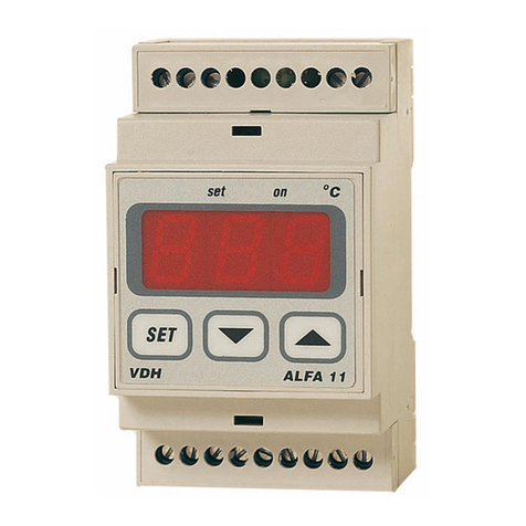
The ALFA(NET) 33 is a digital alarm thermostat for panel mounting. The thermostat watches the
minimum and maximum temperature. The ALFA(NET) 33 has one relay for both alarms.
TheALFANET 33 has a RS 485 network connectionso it canbe readout and adjusted on the Alfanet.
*Installation.
On the topside of the ALFA(NET) 33 you can see how the sensor, power supply and relay has to be
connected.
After connecting the ALFA(NET) 33 to the power supply, a self test function is started. As this test is
finished, the measured temperature appears in the display.
The relay is normally activated. As an alarm appears it will be deactivated and the led 'on' will light-up
in the display.
*Control.
The ALFA(NET) 33 alarm thermostat can be controlled by three pushbuttons on the front;
SET - view / change set points and reset of alarm.
UP - increase a value.
DOWN - decrease a value.
*Viewing setpoints.
Viewing set point of maximum alarm:
By pushing the SET key first and then the UP key simultaneously the maximum alarm set point
appears in the display. The led 'set high' starts blinking.
Viewing set point of minimum alarm:
Bypushing the SET keyfirstand then the DOWN keysimultaneouslythe maximum alarm set point
appears in the display. The led 'set low' starts blinking.
A few seconds after releasing the keys the set point disappears and the measured temperature is
shown in the display again.
*Changing set points.
Push the SET key together with the UP or DOWN keyand the maximum alarm set point or minimum
alarm setpoint appears in the display. Release both keys.
Now push the SET key again and with the UP or DOWN keys the set point can be changed. A few
seconds after releasing the keys the measured temperature shows again in the display.
2
*Actions of the alarm functions.
TheALFA(NET) 33 alarm thermostathasaminimumalarm andamaximumalarmboth with thereown
set point. It is possible to adjust two different kinds of alarms (PARAMETER 27) namely:
Fail safe alarm relay normally activated, with alarm it falls off and the led 'alarm' is on. So on
power failure the alarm relay also falls off. or a
Control alarm relay normally not activated, with alarm the relay will be activated and the led
'alarm' will be on.
PARAMETER 28 can be used to adjust an auto reset alarm or a hold alarm, after temperature
recovers.
It is also possible to give both set points their own offset and differential (see function diagram). For
each alarm an alarm-delaytime (PARAMETER 23 and 24) canbe set. Whenan alarm occurs, the led
'alarm' first starts to blink. If the temperature will recover within the delay time, no alarm occurs. If an
alarm will comethroughafterthe delaytimetheled 'alarm'is oncontinuouslyandthedisplayalternates
between the temperature and 'H' for high-alarm (max.) or 'L' for low-alarm (min.) to indicate the alarm.
To reset an alarm, press the SET key.
*Setting internal parameters.
Next to the adjustment of the set point, some internal settings are possible like differential, sensor-
offset, setpoint range.
By pushing the DOWN key for more than 10 seconds, you enter the 'internal programming menu'. In
the left display the upper- and lower-segment are blinking. Withthe UP and DOWN keys the required
parameter can be selected (see the parameter table). If the required parameter is selected, the value
can be read-out by pushing the SET key. Pushing the UP or DOWN keys, allows you to change the
value of this parameter. If no keyis pushed for 20 seconds, the ALFA(NET) 33 changes to it's normal
operation mode.
*Sensor adjustment.
The sensor can be adjusted by using the Sensor Offset (parameter 04). Indicates the ALFA(NET) 33
e.g. 2C too much, the Sensor Offset has to de decreased by 2C.
*Error messages.
In the display of the ALFA(NET) 33 the following error messages can appear:
E1 - Sensor broken. Solution:
- Check if the sensor is connected correctly.
- Check the sensor (1000at 0C).
- Replace the sensor.
EE - Settings are lost. Solution:
- Re programme the settings.
-L- - In case of sensor short-circuit the display alternates between error-code E1
and -L-, as indication for a short-circuit sensor.
-H- - In case of open-circuit sensor the display alternates between error-code E1
and -H-, as indication for a open circuit sensor.
3
* Technical data.
Type : ALFA(NET) 33 alarm thermostat
Range : 0/+400C, readout per 1C
Supply : 230 Vac (or else see product sticker)
Relay : SPDT 250V/16A(C-NO), 8A(C-NC) (cos phi=1)
Communication : RS 485 Network (2xtwisted pair shielded) only at ALFANET model.
Control : through pushbuttons on the front.
Front : Polycarbonate IP65
Sensor : Pt1000/2-wire.
Dimensions : 35 x 77 x 71,5mm (hwd)
Panel cut-out : 28 x 70mm (hw)
- Provided with memory protection during power failure.
- Connection with screw terminals on the backside.
- Equipped with self test function and sensor failure detection.
- Special version are available upon request.
*Parameters ALFA(NET) 33.
PARA-
METER DESCRIPTION PARAMETER RANGE DEFAULT
VALUE
02
03
04
10
11
21
22
23
24
25
26
27
28
Minimum set point
Maximum set point
Offset temperature sensor
Startup delay after power failure
Relay on at sensor failure
Differential maximum alarm
Differential minimum alarm
Time delay maximum alarm
Time delay minimum alarm
Offset set point High (Max.)
Offset set point Low (Min.)
Relay alarm function
(0=fail safe 1=control)
Auto reset alarm after temp.
recovering (0=hold)
0..+400C
0..+400C
-15..+15C
0..99 min.
0 = No
1 = Yes
1..15C
1..15C
0..99 min.
0..99 min.
0..+20C
-20..0C
0 = No
1 = Yes
0 = No
1 = Yes
0
+400
0
0
0
1
1
0
0
+1
-1
0
0
90
95
96
97
98
99
Network number
Software version
Production year
Production week
Serial number (x1000)
Serial number (units)
1..250
0..255
00..99
1..52
0..255
0..999
1
-
-
-
-
-
* Function diagram.
4
If applicable
*Dimensions.
*Connection diagram.
*Address.
VDH Products BV Tel: +31 (0)50 - 30 28 900
Produktieweg 1 Fax: +31 (0)50 - 30 28 980
9301 ZS Roden Email: info@vdhproducts.nl
The Netherlands Internet: www.vdhproducts.nl

Other VDH Thermostat manuals

VDH ALFANET 72 User manual

VDH

VDH ALFANET 72 User manual

VDH ALFA 23 DP User manual

VDH

VDH ALFA 23 DP User manual

VDH ALFA 51 PI User manual

VDH

VDH ALFA 51 PI User manual

VDH ALFA 72-VS User manual

VDH

VDH ALFA 72-VS User manual

VDH ALFA(NET) 51 User manual

VDH

VDH ALFA(NET) 51 User manual

VDH ALFA 13 DP Pt100 User manual

VDH

VDH ALFA 13 DP Pt100 User manual

VDH Alfanet 95 User manual

VDH

VDH Alfanet 95 User manual

VDH MC 785D User manual

VDH

VDH MC 785D User manual

VDH ALFA(NET) 71 PI User manual

VDH

VDH ALFA(NET) 71 PI User manual

VDH ALFA 71 MOD User manual

VDH

VDH ALFA 71 MOD User manual

VDH ALFA 71 PI User manual

VDH

VDH ALFA 71 PI User manual

VDH ALFA 33 DP User manual

VDH

VDH ALFA 33 DP User manual

VDH ALFA 75-MTT User manual

VDH

VDH ALFA 75-MTT User manual

VDH ALFANET 31 User manual

VDH

VDH ALFANET 31 User manual

VDH ALFA 13 User manual

VDH

VDH ALFA 13 User manual

VDH ALFANET 71 User manual

VDH

VDH ALFANET 71 User manual

VDH ALFA 71 PI User manual

VDH

VDH ALFA 71 PI User manual

VDH ALFA-45 User manual

VDH

VDH ALFA-45 User manual

VDH ALFANET 85 User manual

VDH

VDH ALFANET 85 User manual

VDH ALFA 71 User manual

VDH

VDH ALFA 71 User manual

VDH ALFA 51 User manual

VDH

VDH ALFA 51 User manual

VDH ALFA 13 DP User manual

VDH

VDH ALFA 13 DP User manual

VDH ALFANET 33 User manual

VDH

VDH ALFANET 33 User manual

VDH PROBA 5 Compact User manual

VDH

VDH PROBA 5 Compact User manual

Popular Thermostat manuals by other brands

Nanjing Acmelec Electric AE-Y310 User manual and installation instructions

Nanjing Acmelec Electric

Nanjing Acmelec Electric AE-Y310 User manual and installation instructions

White Rodgers 1F80-361 Installation and operation instructions

White Rodgers

White Rodgers 1F80-361 Installation and operation instructions

Ferro GT10 user manual

Ferro

Ferro GT10 user manual

White Rodgers 1F85ST-0422 Installation and operating instructions

White Rodgers

White Rodgers 1F85ST-0422 Installation and operating instructions

Siemens Acvatix RTN81 Mounting instructions

Siemens

Siemens Acvatix RTN81 Mounting instructions

Genebre 3931K manual

Genebre

Genebre 3931K manual

McQuay MT 168 0-10 VDC/4-20mA Installation and maintenance manual

McQuay

McQuay MT 168 0-10 VDC/4-20mA Installation and maintenance manual

thermotouch 4.3dC Installation & user guide

thermotouch

thermotouch 4.3dC Installation & user guide

wodtke FT 1 operating manual

wodtke

wodtke FT 1 operating manual

Landis & Gyr Chronogyr operating instructions

Landis & Gyr

Landis & Gyr Chronogyr operating instructions

Lennox ComfortSense L5732U installation instructions

Lennox

Lennox ComfortSense L5732U installation instructions

BECA BAC-2000 Series user guide

BECA

BECA BAC-2000 Series user guide

Radio Thermostat CT100 Operation guide

Radio Thermostat

Radio Thermostat CT100 Operation guide

Heltun HE-HT01 quick start guide

Heltun

Heltun HE-HT01 quick start guide

White Rodgers 1F60-22 Installation & operating manual

White Rodgers

White Rodgers 1F60-22 Installation & operating manual

Honeywell RTH6300B operating manual

Honeywell

Honeywell RTH6300B operating manual

Baxi 720644701 Installation & user's instructions

Baxi

Baxi 720644701 Installation & user's instructions

RBM 386.00.22 user manual

RBM

RBM 386.00.22 user manual

manuals.online logo
manuals.online logoBrands
  • About & Mission
  • Contact us
  • Privacy Policy
  • Terms and Conditions

Copyright 2025 Manuals.Online. All Rights Reserved.