VDH ALFA 75 RTDF User manual

Description: Alfa(net) 75 RTDF -50/+50°C Pages: 8 Doc.no: 150014
Type: Manual By: BVDB Version: 1.0
File: Do150014 ALFANET 75 RTDF -50+50°C
V10 EN.docx
Signed: Date: 19-01-2015
VDH Products BV
Manual ALFA(NET) 75 RTDF
-50/+50°C
1Function
The ALFA(NET) 75 RTDF is a panel mount real-time defrost thermostat with various defrost- and
fan-control settings. The thermostat has three relays outputs for function cooling, fan and defrost.
The room- and defrost-temperature are being measured by two SM811 2-wire temperature
sensors.
The ALFANET 75 RTDF is provided with an RS-485 network connection and can be readout or set by
an PC with the ALFANET program connected thru an ALFANET PC-Interface.
2Installation
On the connection diagram of the ALFA(NET) 75 RTDF is shown how the sensors, power supply,
relays and optional network are to be connected. After connecting the ALFA(NET) 75 RTDF to the
power supply, a self-test function is started. As this test is finished, the measured room
temperature of the temperature sensor (control) appears in the display.
3Control
The ALFA(NET) 75 RTDF thermostat can be controlled by four pushbutton on the front.
These keys are;
SET - view / change set value and reset alarm.
∏ UP - increase set value.
π DOWN - decrease set value.
°C - hidden push button above SET key and behind °C symbol.
4Viewing/changing setpoint
By pushing the SET key the setpoint appears in the display. The decimal point of the last display starts
blinking, to indicate this readout. A few seconds after releasing the SET key the setpoint disappears and the
measured temperature is shown again in the display.
To change the setpoint push the SET key, release the SET key. Now push the SET key again together with the
UP or DOWN keys to change the setpoint. A few seconds after releasing the keys the measured temperature
(control) shows again in the display.

ALFA(NET) 75 RTDF -50/+50°C Doc.no.: 150014
version 1.0
Page 2of 8
5Status of the relays
By pushing the hidden °C key the display shows the status of the relays. Each display segment
shows the status of the relay output, showing =off, =on and on last segment=natural defrost
active. The code means relay 1(compr.) and 2(fan) are on and relay 3(defr.) is off.
6View defrost sensor (if present)
By pushing the UP key the defrost temperature appears in the display. A few seconds after
releasing the UP key the defrost temperature disappears and the measured temperature (control)
is shown again.
7Manual starting/stopping of defrost
The defrost cycle is automatic started and stopped. These defrost settings thru internal
parameters.
Stop defrost: If there is a defrost cycle active, the defrost can be manually stopped by pushing
the UP and the DOWN keys simultaneously.
Start deforst: If there is no defrost cycle active, the defrost can be manually startet by pushing
the UP and the DOWN keys simultaneously.
8Fan control
The ALFANET 75 RTDF has several parameters for fan-control. Normally the fan is always active.
Accept for one of the following parameters to be set to 1, the fan can be stopped;
Parameter 20 = 1: Fan switch differential active
The fan is only active when the defrost temperature is “parameter 21” lower than the
measured control temperature. Fan on: Tdefr. < (Tcontrol-Tfandiff.(P21)) As there are no
other conditions to switch the fan off.
Parameter 25,26: Fan on-delay after defrost
The fan is switched off during defrost and to prevent blowing in hot-air in the room after
defrost and the dripping-off time (P27), there are two conditions which can be set;
a: The fan is blocked until the defrost sensor measures a temperature lower than the
temperature setting of parameter 25.
b: The fan is blocked until the defrost-delay-time of parameter 26 has stopped. Unless the
defrost sensor has reached the temperature setting of parameter 25.
Parameter 22 = 1: Compressor off than fan off
The fan deactivates as the compressor deactivates, with a delay of “parameter 23” minutes.
Provided that there is no other conditions to deactivates the fan.

ALFA(NET) 75 RTDF -50/+50°C Doc.no.: 150014
version 1.0
Page 3of 8
9Defrost control
The automatic defrost is started by the defrost cycle-time (P30) and stopped by the maximum
defrost-time (P31) or sooner by reaching the maximum defrost-temperature (P32). Further has
the ALFA(NET) 75 RTDF additional parameters to control defrost;
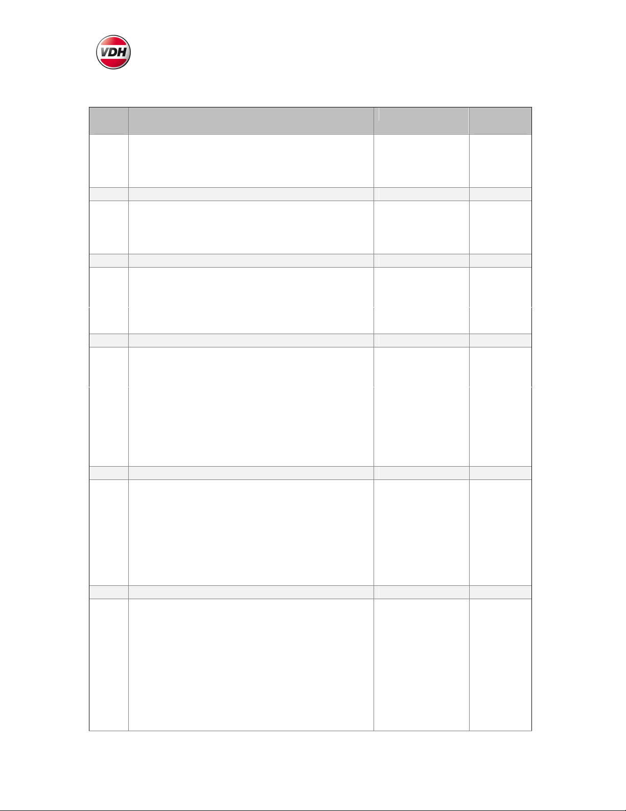
Parameter 24: Defrost mode
The ALFA(NET) 75 RTDF has two defrost modes;
P24 = 0 While defrosting only the fan activates. (Natural defrost)
P24 = 1 While defrosting the relay DEFR. Activates. (Hotgas / Electrical defrost)
Parameter 34: Defrosting on compressor-time (if P60 = 0)
P34 = 0 In this case parameter 30 is the chosen defrost interval-time.
P34 = 1 In this case the defrost is started as the compressor has been active for
“parameter 30”hours.
Parameter 60 = 1: Defrost based on real-time clock
In this case the defrost is started at fixed times, set with parameters P61 until P72.
Parameter 36 = 1: The ALFA(NET) 75 RTDF starts with defrost on power-up
After power-up the ALFA(NET) 75 RTDF first starts with a delay of “parameter 37” minutes
before starting defrost, while in delay the ALFA(NET) 75 RTDF works normally.
Parameter 33 = 1: Compressor active at defrost. (if P24 = 1)
For hot-gas defrost systems the compressor needs to be activated while defrosting. After
defrost the drip-off-time (P27) starts. During this time the defrost-relay and the compressor
are not active, so the cool-unit can drip-off.
Remark: The defrost-sensor is default not active (parameter P08=0) and
the defrost-mode is default set to natural-defrost (parameter P24=0) means
defrost-relay not active.
10 Alarm
As a failure or alarm occurs, an error messages is shown in the display. The ALFA(NET) 75 RTDF
remembers it’s error message, although it is already solved. The error message is resettable with
the SET key. As if after pressing the SET key (= reset alarm) the alarm still is not solved than the
ALFA(NET) 75 RTDF displays the temperature and the error message alternated. Is the alarm
solved, then the error message disappears and the temperature is displayed normally.
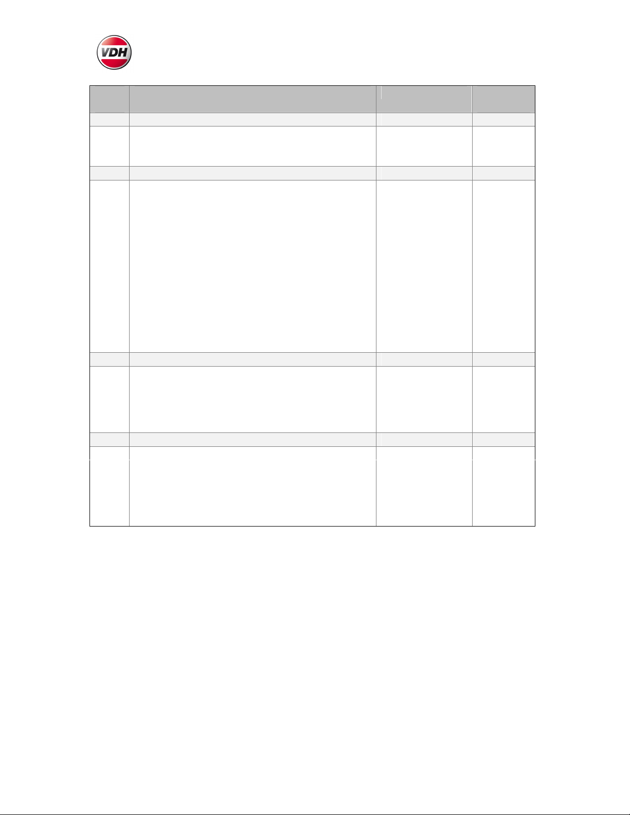
11 Error messages
In the display of the ALFA(NET) 51 PI the following error messages can appear:
Lo1 - Minimum alarm. Solution E1:
Hi1 - Maximum alarm. - Check if the sensor is connected correctly.
E 1 - Control Sensor failure. - Check sensor (1000Ω/25°C).
E 2 - Defrost Sensor failure - Replace sensor.
Reset Alarm. When a error-messages appears it can be resetted by pushing the SET key.

ALFA(NET) 75 RTDF -50/+50°C Doc.no.: 150014
version 1.0
Page 4of 8
12 Adjustment sensors
The temperature sensor (control) can be adjusted by using the Sensor Offset parameter 05.
The defrost sensor can be adjusted by using the Sensor Offset parameter 07.
Indicates a Sensor e.g. 2°C too much, then the according Sensor Offset has to be decreased with
2°C.
13 Technical data
Type
ALFA
7
5
RTDF
o
r
ALFANET 75 RTDF
Range
-
5
0
,0/+5
0
.0
°C
R
eadout
per 0,1°C
Supply
1
2 V
a
c
/ 16,5 Vdc
(
-
5/+10%
)
Or else see sticker
Display
3
-
digit
7
-
segment
LED display
Status LED’s
COMPR., FAN and DEFR.
On display thru hidden
°C
key
Sensor
SM
811 2
-
Wire
PTC 1000
Ω
/25°C
Rela
y
s
Ry1
Cool
= SPST (NO)
250V/8A cos
n
=1 o
r
250V/5A cos
n
=0.4
Ry2 Fan = SPST (NO) 250V/8A cosn=1 or 250V/5A cosn=0.4
Ry3 Defrost = SPDT (NO/NC) 250V/8A cosn=1 or 250V/5A cosn=0.4
Relays have one common (C)
Communicati
on
RS
-
485 Netw
o
rk
Twisted
-
pair
shielded
, min. 0,5mm
2
only at ALFANET A, B, 0V (Twist A and B)
Control
By four push buttons
O
n
t
h
e
front
Front
Polycarbonat
e
Dimensions
35
x 7
7
x
71,5
mm
(
H x W x D
)
Panel
cut out
29
x 7
0
mm
(
H x W
)
Accuracy
+/
-
0,5%
of the range
- Provided with memory protection during power failure.
- Connection with screw terminals.
- Equipped with senor failure detection.
- Special versions are on request available.
14 Setting internal parameters
Next to the adjustment of the setpoint, internal settings can be made like differential, sensor
adjustments, setpoint-range, compressor-, fan-, defrost- and alarm-settings.
Push the DOWN key for more than 10 seconds, to enter the 'Internal Programming Menu'. In the
left display the upper- and lower-segment are blinking . With the UP and DOWN keys the
required parameter can be selected (see the parameter table).
If the required parameter is selected, the value can be read-out by pushing the SET key. Pushing
the UP or DOWN key together with the SET key to change the value of this parameter.
If after 20 seconds no key is pushed, the ALFA(NET) 75 RTDF changes to the normal operation
mode.

ALFA(NET) 75 RTDF -50/+50°C Doc.no.: 150014
version 1.0
Page 5of 8
14.1 Parameters ALFA(NET) 75 RTDF
Para
-
meter
D
es
c
ri
ption
P
arameter
Range
Default
value
01
Switching differential
0.1 ... 15.0°C
0.5
02
Minimum setpoint setting
-
50.0 … +50.0°C
-
50
03
Maximum setpoint setting
-
50.0 … +50.0°C
+50
04
Read out above
-
10°C per 1°C
0 = No, 1 = Yes
0
Sensor
-
settings
05
Offset Control
-
sensor
(room)
-
15.0 …
+15.0°C
0.0
06
Read out Defrost
-
sensor
-
-
07
Offset Defrost
-
sensor
-
15.0 … +15.0°C
0.0
08
Defrost
-
sensor present
0 = No, 1 = Yes
0
Cooling
-
settings
10
Start
-
up delay cooling
0 … 99
0
1
1
Switch
-
off delay cooling
0 … 99
0
1
2
Parameter 10/11 in
seconds or minutes
0 = Sec., 1 = Min.
0
1
3
Minimum on
-
time cooling
0 … 99 Minutes
0
1
4
Minimum off
-
time cooling
0 … 99 Minutes
0
Fan
-
settings
20
Switching differential fan active
0 = No, 1 = Yes
0
21
Switching differential fan
0 … +50.0°C
2.0
22
Fan off as compressor is off
0 = No, 1 = Yes
0
23
Switch
-
off delay fan
0 … 99 Minutes
0
24
Defrost mode
0 = only fan
-
relay,
1 = only defrost-relay
0 = Natural
1 = Hotgas / Elec.
0
25
Switch
-
on delay
-
temperature fan after defrost
-
50.0 … +50.0°C
2.0
26
Switch
-
on delay
-
time fan after defrost
0 … 99 Minutes
0
27
Dripoff
-
time
0 … 99 Minutes
0
Defrost
-
settings
30
Defrost
-
interval
-
time
1 …99 Hours
12
31
Maximum defrost
-
time
0 … 99 Minutes
15
32
End of defrost temperature
-
50.0 … +50.0°C
2.0
33
Compressor on while defrosting
0 = No, 1 = Yes
0
34
D
efrosting on compressor
-
time
0 = No, 1 = Yes
0
35
Temperature display locked during defrost cycle
0 = No, 1 = Yes
0
36
Start with defrost after power
-
up
0 = No, 1 = Yes
0
37
Defrost on
-
delay after
power
-
up
0 … 99 Minutes
0
Alarm
-
settings
40
Alarm mode
0 = None
1 = Absolute
2 = Relative
1
41
Minimum alarm setpoint
-
50.0 … +50.0°C
-
50.0
41
Maximum alarm setpoint
-
50.0 …+50.0°C
+50.0
43
Time
-
delay minimum alarm
0 … 99 Minutes
0
44
Time
-
delay
maximum alarm
0 … 99 Minutes
0
45
Control
-
delay after power
-
failure
0 … 99 Minutes
0
46
Compressor on at control
-
sensor failure
0 = No, 1 = Yes
0
47
Compressor off at minimum alarm
0 = No, 1 = Yes
1

ALFA(NET) 75 RTDF -50/+50°C Doc.no.: 150014
version 1.0
Page 6of 8
Para
-
meter
D
es
c
ri
ption
P
arameter
Range
Default
value
Real
-
time settings
50
Real
-
time hours
0 … 23
Hours
-
51
Real
-
time minutes
0 … 59 Minutes
-
52
Time correction (at real
-
time clock)
in Minutes/Year
-
99 … +99
Min.
/Yr
0
Real
-
time defrost settings
60
Real
-
time defrost active
0 = No, 1 = Yes
61
Defrost
-
time 1 (Hours)
0 … 23 / Off Hours
Off
62
Defrost
-
time 1 (Minutes) steps 10 Min.
0 … 50 / Off Min.
Off
63
Defrost
-
time 2 (Hours)
0 … 23 / Off Hours
Off
64
Defrost
-
time 2 (Minutes) steps 10 Min.
0 … 50 / Off Min.
Off
65
Defrost
-
time 3 (Hours)
0 … 23 / Off Hours
Off
66
Defrost
-
time 3 (Minutes)
steps 10 Min.
0 … 50 / Off Min.
Off
67
Defrost
-
time 4 (Hours)
0 … 23 / Off Hours
Off
68
Defrost
-
time 4 (Minutes) steps 10 Min.
0 … 50 / Off Min.
Off
69
Defrost
-
time 5 (Hours)
0 … 23 / Off Hours
Off
70
Defrost
-
time 5 (Minutes) steps 10 Min.
0 … 50 / Off
Min.
Off
71
Defrost
-
time 6 (Hours)
0 … 23 / Off Hours
Off
72
Defrost
-
time 6 (Minutes) steps 10 Min.
0 … 50 / Off Min.
Off
Day/night settings
80
Night
-
shift (offset) of setpoint
-
20.0 … +20.0°C
0.0
81
Start day (Hours)
0 … 23 / Off Hours
Off
82
Start day (Minutes) steps 10 Min.
0 … 50 / Off Min.
Off
83
Start night (Hours)
0 … 23 / Off Hours
Off
84
Start night (Minutes
)
steps 10 Min.
0 … 50 / Off Min.
Off
General
90
Netw
o
rk
-
num
b
er
(
only
at
ALFANET)
1
..
.
250
1
95
Software versi
on
-
-
96
Producti
on
yea
r
-
-
97
Producti
on
week
-
-
98
Seri
al
num
b
er (x1000)
-
-
99
Seri
al
num
b
er (
units
)
-
-

ALFA(NET) 75 RTDF -50/+50°C Doc.no.: 150014
version 1.0
Page 7of 8
15 Connections
Transformer needed at 230Vac
power supply.
This manual suits for next models
1
Table of contents
Other VDH Thermostat manuals
Popular Thermostat manuals by other brands

Airzone
Airzone ACUAZONE IBPRO32 user manual

PSG
PSG HS-4024U Installation and operating instructions

ELEKTRA
ELEKTRA MWD5-1999 user manual

meitav-tec
meitav-tec SUPER-SI Series User's manual & installation instructions

Honeywell
Honeywell INNCOM e7w troubleshooting guide

Honeywell Home
Honeywell Home TH8110R1008/U manual