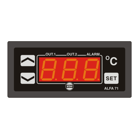
VDH ALFANET 85 User manual

1
User manual
ALFANET 85
Cool thermostat with fan
and defrost control
VDH doc. 080645 Version: v1.0 Date: 19-05-2008
Software: ALFANET85 File: Do080645.WPD Range -40/+50°C
*Installation.
On the side of the ALFANET 85 and on the connection diagram is shown how to connect sensors,
power supply and the relays.
After connecting the ALFANET 85 to the power supply a self-test function is started. Next the
measured temperature of the control sensor is shown in the display (normal operation mode).
*Control.
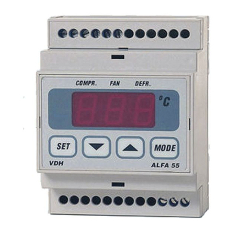
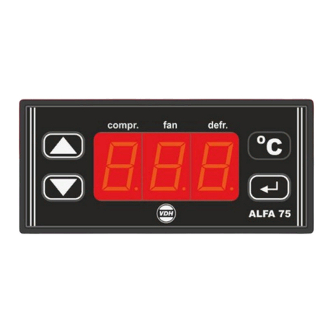
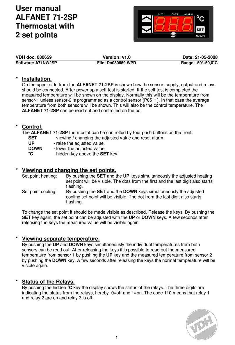
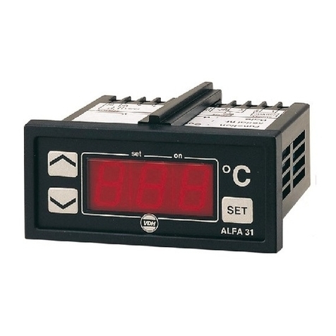
The ALFANET 85 thermostat can be controlled by four push buttons on the front.
These keys are:
SET : view/change the set point
UP : increase the set point
DOWN : decrease the set point
DEFROST : manual start/stop the defrost
*View set point.
By pushing the SET key, the set point is shown. Also the decimal point of the most right display
starts flashing. A few seconds after releasing the SET key, the set point disappears and the
measured value is shown again.
*Changing set point.
Push the SET key to show the set point. Release the set key. By pushing the SET key
simultaneously with the UP or DOWN keys the set point can be changed. A few seconds after
releasing the set key the measured value is shown on the display.
*Read-out defrost sensor.
Push the UP key to show the value of the defrost temperature sensor.

2
*View clock time.
Push the UP and DOWN keys simultaneously. The display will show the present time. The decimal
point between hours and minutes starts flashing.
*Changing time.
Push the UP and DOWN key simultaneously to show the time. By pressing the SET key
simultaneously with the UP or DOWN key the time can be set. A few seconds after releasing the
keys, the measured value is shown in the display.
*Start/stop defrost cycle.
The defrost cycle is automatically started and stopped. Settings by via the Internal Parameters.
The defrost can be changed manually:
STOP : If defrost is on, the defrost can be stopped manually by pushing the DEFROST
key.
START : If no defrost is on, the defrost can be started manually by pressing the DEFROST
key.
*Setting internal parameters.
Next to the adjustment of the set point a number of internal settings are possible, like differentials,
sensor offsets, set point range, cooling settings, fan settings and defrost settings.
By pushing the DOWN key for more than 10 seconds, the 'Internal Parameter Menu' is entered.
The display shows P01. By the UP and DOWN keys the required parameter can be selected (see
table for parameters).
When the required parameter is selected, press the SET key to show the value of thisparameter.
By pushing the UP or DOWN keys the parameter value can be changed.
If for 30 seconds no key is pressed, the ALFANET 85 will return to its normal operation mode and
the changes are stored.
*Adjustment of sensors.
The control sensor can be adjusted withe the 'offset control sensor' (parameter 05). Indicates the
control sensor e.g. 1,2°C too much, the sensor offset should be reduced with 1,2°C. The defrost
sensor is adjusted with the 'offset defrost sensor' (parameter 07).
*Reset of alarm.
During alarm the alarm relay and the internal buzzer are activated. By pressing the SET key the
buzzer will stop and the alarm relay, depending on the internal settings, will drop. The error
message remains flashing in the display, until the cause of the failure is solved.

3
*Fan control options.
The ALFANET 85 has various settings for the evaporator fan. Normally the fan runs continuously,
except if one the the parameters mentioned below is set to 1.
Parameter 20 = 1 Fan switch differential active
The fan only runs if the temperature of the defrost sensor is lower than the temperature of the
control sensor minus the fan switch differential (P 21)
Parameter 24 = 1 Fan off during defrost.
To prevent that after the defrost and drip-off time the fan starts to run and warm air is blown
into the cold room, two conditions can be set:
a. The fan is blocked until the defrost sensor reaches a temperature lower than the
temperature set with parameter 25.
b. The fan is blocked until the defrost delay of parameter 26 has passed, unless the defrost
sensor reaches the switch-on temperature of parameter 25. If the defrost sensor is broken,
the ALFANET 85 will run he time of parameter 26 before the fan is started.
Parameter 22 = 1 Fan off if cooling off.
The fan is stopped if the cooling is stopped. This is done through the delay of parameter 23.
*Defrost control options.
The automatic defrost is started by the defrost interval time and stooped after the maximum
defrost time or sooner is the defrost sensor reaches the set end-of-defrost temperature. The
ALFANET 85 has various automatic defrost options that can be set with the following parameters.
Parameter 34 = 0 Defrost with fixed defrost intervals.
Hereby parameter 30 is always the selected interval time.
Parameter 34 = 1 Defrost based on the total cooling run time.
Hereby the defrost is started if the cooling has run the time set with parameter 30.
Parameter 38 = 1 The ALFANET 85 start with defrost when switched on.
The ALFANET 85 starts with a defrost cycle if the ALFANET 85 is switched on, whereby first
the defrost-swtich-on-delay (parameter 39) is passed. During this delay the cooling can be on,
after which the defrost is started.
Parameter 33 = 1 For hot-gas-defrost systems the cooling is switched on during defrost.
After the defrost the drip-off time (parameter 37) is started. During this time the defrost relay is
not active and the evaporator can drip off. During this time the cooling will not run.

4
*Parameters ALFANET 85.
Para-
meter Description Range Default
Value
P 01
P 02
P 03
P 04
P 05
Switch differential cooling
Minimum set point setting
Maximum set point setting
Offset control sensor
Offset defrost sensor
0.1..15.0C
-40.0..50.0C
-40.0..50.0C
-10.0..10.0C
-10.0..10.0C
0.5
-40.0
50.0
0.0
0.0
P 10
P 11
P 12
P 13
P 14
Switch on delay cooling
Switch off delay cooling
Parameter 10/11 in seconds or
minutes
Minimum on time cooling
Minimum off time cooling
0..99
0..99
0 = sec 1 = min
0..99 minutes
0..99 minutes
0
0
0
0
0
P 20
P 21
P 22
P 23
P 24
P 25
P 26
Fan switch differential active
Switch differential fan
Fan off if cooling off
Switch off delay fan
Fan off during defrost
Switch on temperature fan after
defrost
Switch on delay after defrost
0 = No 1 = Yes
0.1..50.0C
0 = No 1 = Yes
0..99 minutes
0 = No 1 = Yes
-50.0..50.0C
0..99 minutes
0
2.0
0
0
0
2.0
0
P 30
P 31
P 32
P 33
P 34
P 35
P 36
P 37
P 38
P 39
Defrost interval time
Maximum defrost time
End-of-defrost temperature
Cooling on during defrost
Defrost on compressor run time
Display fixed during defrost
Maximum display fixed time
after defrost
Drip-off time
Start with defrost after power
failure
Defrost delay after start-up
1..99 hours.
0..99 minutes
-40.0..50.0C
0 = No 1 = Yes
0 = No 1 = Yes
0 = No 1 = Yes
0..99 minutes
0..99 minutes
0 = No 1 = Yes
0..99 minutes
12
15
2.0
0
0
0
10
0
0
0
P 40
P 41
P 42
P 43
P 44
P 45
P 46
P 47
P 48
Defrost on real time bases
Start defrost 1
Start defrost 2
Start defrost 3
Start defrost 4
Start defrost 5
Start defrost 6
Start defrost 7
Start defrost 8
0 = No 1 = Yes
00:00..23:59,OFF
00:00..23:59,OFF
00:00..23:59,OFF
00:00..23:59,OFF
00:00..23:59,OFF
00:00..23:59,OFF
00:00..23:59,OFF
00:00..23:59,OFF
0
00:00
04:00
08:00
12:00
16:00
20:00
OFF
OFF
P 50
P 51
P 52
P 53
P 54
P 55
P 56
Type alarm
Minimum alarm set point
Maximum alarm set point
Time delay minimum alarm
Time delay maximum alarm
Reset alarm when alarm
disappears
Alarm relay off after manual
reset of alarm
0 = none
1 = absolute
2 = relative
-40.0..50.0C
-40.0..50.0C
0..99 minutes
0..99 minutes
0 = No 1 = Yes
0 = No 1 = Yes
1
-40.0
50.0
0
0
0
0

Para-
meter Description Range Default
Value
5
P 80
P 81
P 82
P 83
Cooling and fan off when door open
Maximum cooling and fan off time
when door open
Control delay after power failure
Cooling on at sensor failure
0 = No 1 = Yes
0..99 min.
0..99 min
0 = No 1 = Yes
1
30
0
0
P 90
P 91
P 95
P 96
P 97
RS 485 network number
Log interval
Software version
Production date
Serial number
1..255
1..60 min
-
-
-
1
10
-
-
-
*Error messages.
In the display of the ALFANET 85 the following alarm messages can be shown.
Lo 1 : minimum alarm control sensor
Hi 1 : maximum alarm control sensor
E 1*: control sensor broken
E 2*: defrost sensor broken
EE1/EE2 : settings are lost
Solution E1/E2 : Check if sensor is connected correctly
Check the sensor (1000/25C)
Replace sensor
Solution EE1/EE2 : Program settings again
*)
-L- In case of a short in the sensor the display will alternate between the error code E.. and -L-
to indicate a short of the sensor
-H- In case op an open sensor circuit the display will alternate between the error code E.. and -
H- to indicate and open sensor circuit.
*Technical data.
Type : ALFANET 85 thermostat
Range : -40/+50C with read-out per 0,1C
Supply : 12 Vdc/ac 50/60Hz (-5/-10%)
Read-out : 4 number 7 segment display
Status LED : cool, fan, defrost, alarm
Relay cooling : SPST 250V/8A (cos phi=1)
Relay defrost : SPST 250V/8A (cos phi=1)
Relay fan : SPST 250V/8A (cos phi=1)
Relay alarm : SPST 250V/8A (cos phi=1)
Control : by four push buttons on the front
Front : polycarbonate
Sensor : 2x SM 811/2m (PTC 1000/25C)
Digital input : door contact (potential free)
Communication : RS 485 (2x twisted pair shielded min. 0.8mm2)
Dimensions : 106x90x58mm (whd)
Accuracy : ± 0,5% of the range
- Provided with memory protection during power failure.
- DIN-rail mounting.
- Provided with self test function and sensor failure detection.
- Special models available upon request.

6
*Connections.

7
*Dimensions.
Table of contents
Other VDH Thermostat manuals