Vdwall LVP605S User manual
LVP605
LED HD Video Processor
USER’S MANUAL

LVP605 User’s Manual http://www.cnledsourcing.com
---------------------------------------------------------------------------------------------------
LED VIDEO PROCESSOR
2
TABLE OF CONTENTS
I. S fety prec utions
3
II. P cking list 4
III. Connections of h rdw re
1. Re r view
5
2. Port description
5
3. Connection di gr m
6
IV. Front l p nel oper tions
1. Di gr m of front l p nel
7
2. Button instructions (oper tion mode)
8
V. Setup
(I) User p r meter setup
12
1. Enter setup of LVP605
12
2. Select l ngu ge
13
3. Output im ge setup
14
4. Text Overl y Setup
15
5. Brightness / contr st / color / Sh rpness
16
6. Audio configur tions
17
7. Hot Sp re setup
17
8. F ctory district setup
18
(II) PIP/POP setup
19
(III) Mos ic setup
21
VI. Specific tions
26
VII.
Copyright info………………………………………………………….28

LVP605 User’s Manual http://www.cnledsourcing.com
---------------------------------------------------------------------------------------------------
LED VIDEO PROCESSOR
3
I. S fety Prec utions
D nger!
There is high voltage in the processor, to prevent any unexpected
hazard, unless you are maintenance, please do not open the cover of the
device.
W rning!
1. This device shall not encounter water sprinkle or splash, please do not
place anything containing water on this device.
2. To prevent fire, keep this device far from any fire source.
3. If this device gives out any strange noise, smoke or smell, please
immediately unplug the power cord from receptacle, and contact local
dealer.
4. Ple se do not plug or unplug DVI sign l c ble if the device is
powered on.
C ution!
1. lease thoroughly read this manual before using this device, and keep
it well for future reference.
2. In the event of lighting or when you are not going to use the device for
a long time, please pull the power plug out of receptacle.
3. Nobody other than professional technicians can operate the device,
unless they have been appropriately trained or under guidance of
technicians.
4. To prevent equipment damage or electric shock, please don’t fill in
anything in the vent of the device.
5. Do not place the device near any water source or anywhere damp.
6. Do not place the device near any radiator or anywhere under high
temperature.
7. To prevent rupture or damage of power cords, please handle and keep
them properly.
8. lease immediately unplug power cord and have the device repaired,
when
1) Liquid splashes to the device.
2) The device is dropped down or cabinet is damaged.
3) Obvious malpractice is found or performance degrades.
LVP605 User’s Manual http://www.cnledsourcing.com
---------------------------------------------------------------------------------------------------
LED VIDEO PROCESSOR
4
II. P cking list
lease unpack the product with care, then check whether all the following
things are included in the package. If anything is found missing, please contact
the dealer.
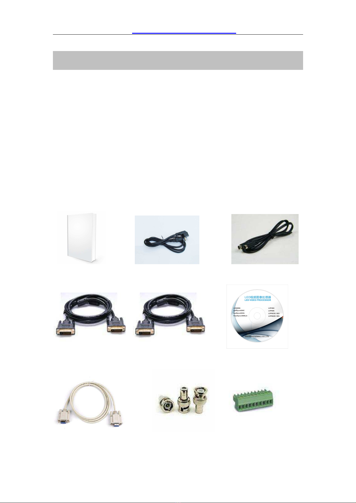
St nd rd ccessories
The accessories supplied with this LED Video rocessor may differ from the
figures contained in the User’s Manual, but they are applicable for the regions
where you live.
DVI cable (150cm), 1pcs
BNC-RCA adapter: 2 pcs, Cabinet stator: 2 pcs, Screws: 6 pcs
User’s Manual ower cord (1.5m)1pcs S-VIDEO cable (1.5m)
,
DVI cable (1.5m), 1pcs DVI cable (0.5m), 1pcs Disk
Rs232 cable (1.5m) BNC-RCA adapter: 3 pcs CB Connector (Audio)

LVP605 User’s Manual http://www.cnledsourcing.com
---------------------------------------------------------------------------------------------------
LED VIDEO PROCESSOR
5
III. Connections of h rdw re
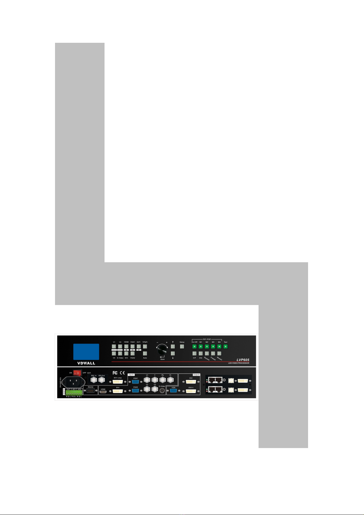
1. Re r view
Figure 1
2. Port description
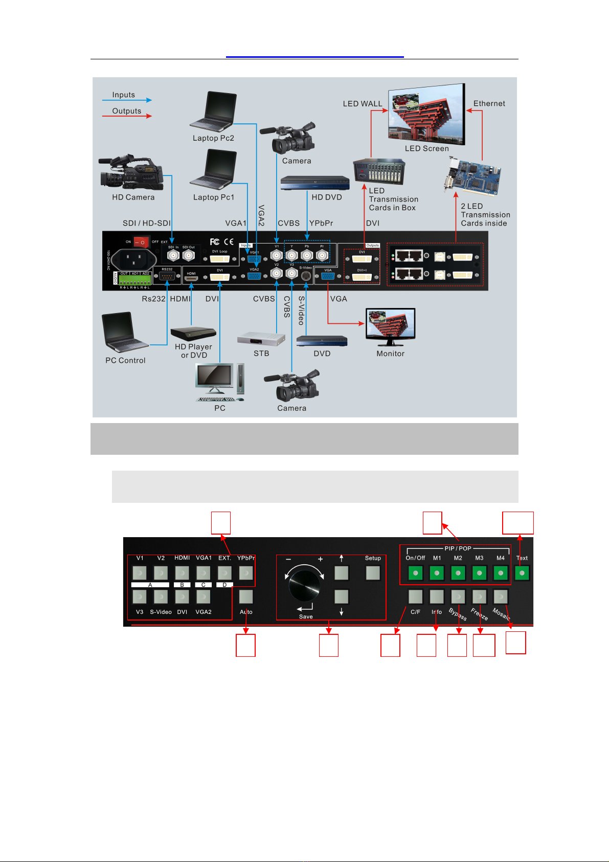
1) Video Input
LVP605 supports 10-channel signal input, including:
ort name Description
V1~V3 3-channel AL/NTSC composite video input
S-Video 1-channel AL/NTSC S-video input
YPbPr
1-ch nnel component HD sign l input
VGA1~VGA2 2-channel computer analog signal input
DVI
1-ch nnel computer DVI digit l sign l input
HDMI
1-ch nnel HDMI digit l HD sign l input
EXT.
1-ch nnel extended sign l input
EXT. input signal can be 1xSDI/HD-SDI or 1xVGA/DVI/HDMI.
2) Audio Input
LVP605 supports 5-channel stereo audio switch. Of which, 3
channels are DVI (only available when the input signals are HDMI
signals), HDMI and SDI audios, the other 2 channels are AD1, AD2
external input audio. AD1 and AD2 can be mapped to the any one
of all video inputs, and will be switched synchronous to the
selection of video input signals.
3) Video Output (DVI)
ort Description
VGA OUT 1-channel analog RGBHV signal output,
it can be connected to a local display
device and used as monitor (it is strongly

LVP605 User’s Manual http://www.cnledsourcing.com
---------------------------------------------------------------------------------------------------
LED VIDEO PROCESSOR
6
recommended to use this port when
operating and setting LVP605).
DVI OUT1 /
DVI OUT2
2 same DVI digital graphic signal output,
it can be connected with external LED
transmission card or LED transmission
box
SDI / HDSDI(OUT)
1-channel digital video signal loop output
DVI Loop OUT 1-channel
computer DVI digital signal loop
output
4) Audio Output (AUDIO OUT)
Corresponds to the selected video input signal, output this
channel audio input signals.
5) Sign ls of other ports
RS232 serial communication port
3. Connection di gr m
LVP605 User’s Manual http://www.cnledsourcing.com
---------------------------------------------------------------------------------------------------
LED VIDEO PROCESSOR
7
IV. Front l p nel oper tions
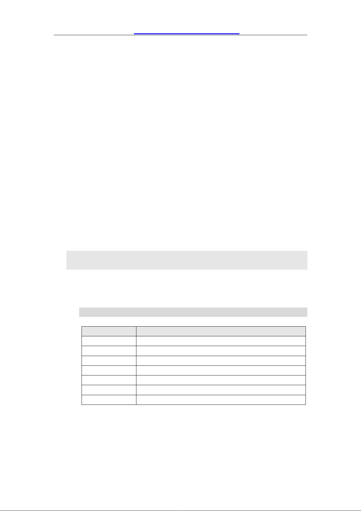
1. Di gr m of front l p nel
1) Input selecting buttons (V1, V2, V3, S-Video, DVI, VGA1, VGA2, YPbPr,
EXT.):
They are used to select input signals
2) Setup buttons (Setup, S ve,
↑,↓,←,→)
They are used to set the image output parameters of the processor.
3
2
1
4
6
5
8
10
9
7
LVP605 User’s Manual http://www.cnledsourcing.com
---------------------------------------------------------------------------------------------------
LED VIDEO PROCESSOR
8
3) VGA uto djustment (Auto)
To automatically adjust VGA input signals
4) Cut / F de switching mode (C/F):
It is used to select signal switching effects, including seamlessly
switching (CUT) and 0.5s, 1.0s and 1.5s Fade in / Fade out.
5) PC sign l byp ss output (Byp ss):
It is used to switch full screen/partial screen display of C signals, and
the indicator will indicate the status of current input signal.
6) Info:
It is used to display current settings and information of processor
7) PIP/POP buttons (ON/OFF,M1,M2,M3,M4):
ON/OFF: to turn on/off PIP/POP functions, when the indicator is on,
you can select any signal coming from different groups or current signal as
I / O by using input selecting buttons.
M1,M2,M3,M4: used to set or switch I / O modes.
8) Mos ic
It is used to turn ON/OFF multi-machine cascade mosaic function. The
indicator indicates current splicing status.
9) Freeze
It is used to turn ON/OFF screen freezing function.
10) Text
It is used to add Text, company logo or animation.
2. Button instructions (oper tion mode):
There are 25 buttons on the frontal panel of LV 605, all these buttons
will be operable after start. they have the following functions as
described below:
1) Select input video source
ort name Description
V1、V2、V3 3-channel AL/NTSC composite video input
S-Video 1-channel AL/NTSC S-video input
YPbPr
1-ch nnel component HD sign l input
VGA1、VGA2
2-channel computer analog signal input
DVI
1-ch nnel computer DVI digit l sign l input
HDMI
1-ch nnel HDMI digit l HD sign l input
EXT.
1-ch nnel extended sign l input(such s SDI/HDSDI)
Switch audio input while operating above buttons; select the audio
signal input from corresponding video input to output it through Audio
OUT.
After selecting input signals, the input signal source you
LVP605 User’s Manual http://www.cnledsourcing.com
---------------------------------------------------------------------------------------------------
LED VIDEO PROCESSOR
9
currently selected such as “input=HDMI” will appear in the first line
of LCD, while the status of current input signals will appear in the
second line of LCD. If there are no valid signals entered, the
message “no valid signal input” will appear in LCD, and the
corresponding indicator will blink and dark screen appear; if the
signal is valid, the format of input signals such as “ 1080p_60Hz ”
will appear in LCD.
2) VGA input uto djustment (Auto)
When the current VGA input source of LVP605 is a valid signal,
press this button, LVP605 will automatically adjust the sampling
parameters of the VGA signals, so as to make VGA picture clean
and complete.
In general, this operation is made only when new VGA signal
source is to be connected in. Sometimes user need repetitively do
such adjustment till VGA picture looks clean, complete and stable.
3) Inform tion displ y (Info)
ress this button to view current settings and information of
LVP605, it consists of 25 items. If you press “Info” again before
LVP605 exit information display, LVP605 will continue to display
the next item of information.
4) Select Cut / F de mode(C/F)
LV 605 can realize seamless switching effect (Cut) or fading
in/out switching effect (Fade) between any two signals from
different groups as listed below.. But if the signals come from the
same group, dark screen will appear.
A B C D
V1,V2, V3,
S-Video
DVI,
HDMI
VGA1
VGA2
EXT
Cut (seamlessly switching): while in this mode, “Cut” will
appear in the third line of LCD, the system can seamlessly switch
between different signals. It is also the default mode of LV 605
Input= HDMI
1080p_60Hz
Cut

LVP605 User’s Manual http://www.cnledsourcing.com
---------------------------------------------------------------------------------------------------
LED VIDEO PROCESSOR
10
after startup.
F de (fading in fading out): while in this mode, “Cut: 1.0s” will
appear in the third line of LCD, the system can realize fading in
fading out switching effect between the signals coming from
different groups. Users can set the switching time of fading in and
fading out as 0.5 seconds,1.0 second or 1.5 seconds.
Notes: Neither Cut mode nor Fade modes applies to YPbPr
signals, that is to say, if you attempt to switch between YPbPr
signals and any other signal, dark screen will appear.
5) PIP / POP(PIP/POP:On/Off,M1, M2, M3, M4)
I / O mode of LV 605 allows user to insert a I window in
current picture, and the size and location of the I window can be
set freely. The signals to be displayed in I window can be either
current signal itself or any signals which are not in the same group
as that of current picture. Here we call current picture “background”,
and call the picture to be overlaid “ I ”. The following paragraphs
will illustrate the operating procedures of this function:
Enter PIP displ y mode: ress On/Off button, its indicator will
illuminate, LV 605 will enter I display mode, then use reselect
button to select I input signals, in the meantime, signals of
background and I and their locations will appear in LCD (see
Figure below):
Ch nge PIP: While in I mode, use Preselect button to select
proper input signals, the preselected signals will be set as I .
Ch nge the b ckground: you must first turn off I mode.
ress buttons to select appropriate input signal as background,
then enter I mode again, and select a new I picture.
Switch PIP/POP displ y mode: LVP605 allows for presetting
4 PIP/POP display modes, each mode allows for setting its own
background and I sizes and locations. While PIP/POP mode is
switched on, user can press the mode switching buttons (M1, M2,
M3, M4) to select appropriate display modes quickly.
6) P rt/Full(Byp ss)
Background:V1
AL
I :VGA
1280X1024 60Hz
This manual suits for next models
1
Table of contents
Other Vdwall Processor manuals

Vdwall
Vdwall LVP605 User manual

Vdwall
Vdwall LVP615U User manual

Vdwall
Vdwall LVP603 series User manual

Vdwall
Vdwall LVP8601 User manual

Vdwall
Vdwall LVP608 User manual

Vdwall
Vdwall LVP605 User manual

Vdwall
Vdwall LVP605 Operating manual

Vdwall
Vdwall LVP606A User manual

Vdwall
Vdwall LVP603 series User manual

Vdwall
Vdwall LVP615 series User manual


