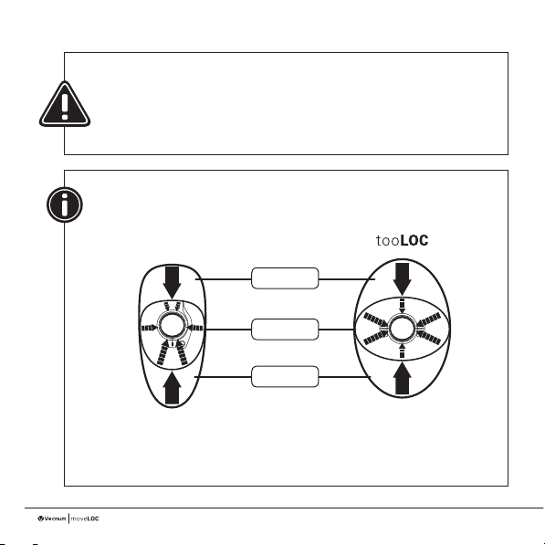
Vecnum moveLOC Indexed User manual

Manual

2
Thanks for buying the moveLOC
dropper post.
You have purchased a product, which is designed, manufactured, assembled and
tested in Germany.
A dropper post is a highly stressed moving part on a mountain bike, which is direct
exposed to dirt. These facts make periodic maintenance for the post necessary.
During the design process, we had a big priority regarding minimum maintenance,
durability and easy servicing. As a result of this, you can do all servicing with a
standard mini tool.
Please read the manual carefully, before installing your moveLOC dropper post at your
bike..
Add. information you can nd on our website
http://vecnum.com/en/products/moveloc/servicefaq/
There will be always the latest version of the manual online.
For a quick an easy installation you will also nd a video tutorial on this website.

3
Intended use:
The moveLOC dropper post is designed for mountain bikes and their purposes.
The installation on a road bike is also permitted
The moveLOC dropper post can handle a max. rider weight of 120 kg.
Installation dimensions:
You can easily nd the suitable length for your moveLOC dropper post by our online
CONFIGURATOR:
http://vecnum.com/en/products/moveloc/congurator
The moveLOC dropper post is only manufactured with diameter 30,9 mm. To adapt the
post to several seat tube diameters, we offer different shims in our online shop. This
standard diameter saves weight and assures a maximum of flexibility using other seat
tube diameters in the future.

4
For all installation and maintenance
on the dropper post:
Push Fail-Safe button
and completely
extend dropper post
Operation instructions:
Please make sure, that you are fully familiar with the function of the moveLOC dropper
post before your rst ride. Due to an operating error you can loose control of your bike,
which can occur an fatal accident.
After a short period of familiarisation, you will shift your moveLOC dropper post
intuitively to the individual height positions. Please exercise the handling at an easy
trail. The moveLOC can be indexed at 4 different height positions, which enables a fast
and repeatable height adjustment.
Don't lower your dropper post completely when using a cable lift (max.
position 3), because the T - bar can damage the shaft sealing unit.
For cleaning the bike you must completely lower the dropper post.
Installation:

5
Position 1 :
pedalling ( maximum position = post completely extended)
The maximum positions should be adjusted in a way, that allows an
ergonomic position for pedalling uphill
Position 2 :
trail ( 40mm lowered referred to maximum position)
This Position is ideal for riding easy trail incl. pedalling section. With 40mm
lowering you will have signicant more ability to move with the bike.
Moreover this, you have the possibility for pedalling on saddle with a
reasonable effectiveness for climbing technical uphills.
Position 3:
Downhill (100 or 90 mm lowered referred to max. Position)
This position is intended for fast downhill sections. With the
feedback of the saddle you can guide your bike precisely.
Position 4:
technical downhill (saddle maximum lowered)
Maximal freedom for movement on the bike for steep
sections, trial skills etc.

6
CONTENT
1- Installation preparation
2- Installation dropper post and saddle
3- Installation remote lever and cable housing
4- Bowden cable installation / replacement and adjustment
5- Easy maintenance and care
6- Trouble shooting and maintenance
7- Guarantee and Warranty

7
universal pliers
5mm
2.5mm

8
We can only guarantee proper function of the moveLOC
dropper post by using a tooLOC seat clamp.
Comparison between a conventional seat clamp and tooLOC seat clamp
conventional seat clamp
uneven force distribution into the seat tube.
This can occur function restrictions for dropper
post.
more even force distribution into the seat
tube for a perfect dropper post function
Forces / working load
Clamping Forces

9
1 - Montagevorbereitung
15gTorx T25
Remove old seat post clamp
1.1
Install tooLOC clamp
1.2

10
Clip in the cable remote at the
dropper post
1.3

11
Screw the cable holder tight at the dropper post body
1.4
Allen key 2.5mm
1Nm

12
2 - Installation dropper post and saddle
Completely extend dropper post
2.1
Press Fail Safe button
and completely extend
seat post

13
For an easy installation, preset
the post roughly to the height
position in the seat tube
and tighten the seat clamp bolts
hand tight
Recommendation:
Please use the supplied assembly
paste for reliable clamping between
post | shim | seat tube
Insert dropper post into
the seat tube
2.2
Tighten seat clamp
Torx T25
2.3

14
Loosen rear bolt
Allen key 5mm
2.4
Remove bolt and nut from upper
rocker of the rail clamp
Put the saddle rail into the lower
rocker of the rail clamp
Put the upper rocker back onto the
saddle rail
Hang up the rear clamp bolt into
the upper rocker
2.5
2.6
2.7
2.8

15
Adjust saddle position
Allen key 5mm
2.9
Tighten rear bolt while pressing on saddle bottom
Tighten front bolt while pressing on saddle nose
Adjust saddle tilting rst, then horizontal position
Allen key 5mm
32mm
8.5°-8.5°
0°
73° default angle

16
Tighten the clamp bolts alternated
Allen key 5mm
2.10
Please check the torque of the clamping
bolts after rst couple of hour used.
- Note maximum torque!
Shake saddle strongly and check the
torque of the bolts again
2.11
6-max. 8Nm

17
The bolts must have 6
supporting threads in the nut.
--> 6 threads (=6mm)
If you use a extreme tilting or a carbon saddle with high oval shaped rails, it
may happen, that the standard M6x30m Titanium bolts do not require the
6mm supporting thread
In our online Shop https://shop.vecnum.com we offer longer bolts M6x35
for this special application
min. 6mm

18
3 - Installation remote lever and cable housing
Loosen bolts for cable clamp on
the remote lever
Allen key 2.5mm
3.1
Remove protective rubber cap from Fail Safe button
3.2
Pull out the remote cable from the housing half way
to enable cutting the cable housing
3.3
Remove remote lever from the cable housing
3.4

19
First set the bolt from
top side, before you
rotate the remote lever
to its nal position
Adjust the position in a way that you
can actuate the trigger with your
thumb in the most ergonomic way
3.5
Tighten the clamp
Allen key 2.5mm
3.6
1Nm

If your frame offers some cable holders in or on top or down tube, you can use the
recommended routing line for the cable
If there is no cable routing for dropper posts with an external actuation
available, you can use our provided universal cable holder pads for
installation
We recommend the routing on the top tube ( ) our on the down tube
( )
If the standard bowden cable length is not long enough, you can order cable and
housing in our online shop by the meter
20
3.7 Cable routing on on the frame
Table of contents
Other Vecnum Bicycle Accessories manuals