VECTECH 966D User manual

VECTECH966D
Lead Free Soldering Station
INSTRUCTION MANUAL
Thank you for purchasing the lead free soldering station. It is designed for lead
free soldering. Please read this manual before operating the unit. Store this manual
in a safe, easily accessible place for future reference.

1. Safety Instruction
Confirm the Tip has been installed before turning on the unit,
otherwise the Heating Element will be broken.
Warning:
In this instruction manual, “Warning”, “Caution”and “Note”are defined as
follows.
Warning: Misuse may potentially cause death of, or serious injury to the user.
Caution: Misuse may potentially cause injury to the user or physical damage to
the objects involved. For your own safety, be sure to comply with these
precautions.
Note: A Note indicates a procedure or the point that is important to the process
being described.
Caution
When the power is on, the tip temperature is very high. Since
mishandling may lead to burns or fire, be sure to comply with the
following precautions.
Don‟t misuse the unit, it is used in accordance with Operation Manual.
Don‟t touch the metallic parts near the Tip.
Don‟t use the product near flammable items.
Advise other people in the work area that the unit can reach a very high
temperature and should be considered potentially dangerous.
Turn off the power while taking breaks and when finished using the unit.
Before replacing parts or storing the unit, turn the power off and allow the
unit to cool to room temperature.
The unit shall only be used with rated voltage and frequency. (Refer to
nameplate back the unit)
Don‟t use or stop the use if the unit is damaged, especially the supply cord.
This machine is equipped with a 3-wire grounding plug and must be plugged
Page 1

into a 3-terminal grounded socket. Do not modify plug or use an ungrounded
power socket. If an extension cord is necessary, use only a 3-wire extension
cord that provides grounding.
Don‟t use the unit for applications other than soldering.
Don‟t rap the soldering iron against the workbench to shake off residual
solder, or otherwise subject the iron to severe shocks.
Don‟t modify the unit.
Use only original replacement parts.
Don‟t wet the unit or use and disconnect the unit when your hands are wet
and without to force the supply cord.
The soldering process will produce smoke, so make sure the area is well
ventilated.
While using the unit, don‟t do anything, which may cause bodily harm or
physical damage.
Children cannot recognize the risks of electrical appliances. Therefore use or
keep the appliance only under supervision of adults and out of the reach from
children.
2. Character
Large power, Digital display and PID control temperature. Rapid heating and
recovery of temperature.
With long life ceramics heater element.
Many kinds of long service life and general tips can be matched and easy to
use.
Digital type calibration and it is easy to operate.
The portable soldering iron uses comfortably.
Original appearance and firm structure.
ESD design.
Tips
(0.12) (0.09) (0.06) (0.047) (0.031)
0.8
?
- 10~C/ - 18~F
0~C
0~C
0~C
0~C
0~C
0~C
0~C
0~C
0~C
0~C
0~C
0~C
0~C
0~C
- 10~C/ - 18~F
- 10~C/ - 18~F
0~C
- 10~C/ - 18~F
- 10~C/ - 18~F
- 20~C/ - 36~F
T- 0.8C
T- 0.5C
T- S4
T- 1.8H
T- H
T- I
T- RT
T- R
+30~C/ +54~F
2(0.08)
T- K
(0.2)
?5
15(0.6)
45~
13(0.51)
T- SI R0.2(0.008)
R0.2(0.008)
T- SB
?2
14(0.55)
(0.08)
60~
15(0.6)
?1.5
(0.06)
T- 1.5C
T- 1.5CF*
45~
T- 4CF*
(0.16)
17(0.66)
?4
T- 4C
T- 3C
?3
17(0.66)
(0.1)
T- 3CF*
45~
45~
T- 2CF*
(0.08)
17(0.66)
?2
T- 2C
T- 1CF*
T- 1C
(0.04)
?1
15(0.6)
60~
T- LB
T- B
T- 1.2LD
T- 3.2D
T- 2.4D
T- 1.6D
T- 1.2D
T- 0.8D
(0.031)
?0.8
45~
17(0.66)
45~
15(0.6)
?0.5
(0.02) (0.08)
?2
15(0.6)
R0.25(0.01)
14(0.5)
7.5
(0.29)
1.8(0.07)
1 (0.04)
25~
25~
1.2(0.04)
3.5(0.13)
(0.29)
7.5
R0.2(0.008)
17(0.66)
19(0.74)
(0.08)
2
?4.2
(0.17)
3.2
(0.1)
(0.2)
17(0.66)
2(0.08)
(0.08)
2
?5.1
17(0.66)
R0.2(0.008)
25(0.98)
R0.5(0.02)
17(0.66)
?1.2(0.047)
0.7(0.028)
25(0.98)
(0.25)
617(0.66)
?3.2
0.5(0.02)
0.5(0.02)
?2.4
17(0.66)
5
(0.2)
(0.1)
317(0.66)
?1.6
0.5(0.02)
0.7(0.028)
?1.2
17(0.66)
17(0.66)
0.6(0.024)
Page 2
Page 15

11. Parts name
iron handle
handle cord
fuse
grounding cord
sponge
socket
power switch
key
display
soldering station
3. Specification
Power Consumption 90W
Range of temperature 80℃~480℃
Temperature Stability ±2℃Without air flow and no load
Max Ambient Temperature 40℃
Working voltage of heating element 28V AC
Tip to ground potential <2mv
Tip to ground resistance <2Ω
Handle Cord Assembly 1.2m
Length of Handle 190mm
Dimension 160 L*105 W*125 H (mm)
Weight 2.3kg
The tip temperature is measured by 191 or 192 thermometer.
Specifications and design subject will be changed without notice.
4. Setting and Operation of the Soldering Station
Caution: Please check whether the power voltage is in accord with rated
voltage in the nameplate.
4.1 Iron Holder and Sponge
Caution: The sponge is compressed. It will swell when moistened with
water. Before using the unit, dampen the sponge with the water
and squeeze it dry. Failure to do so may result in damage to the
soldering tip.
1. Dampen the small cleaning sponge with water and then squeeze it dry. Place
it in the flute of the iron holder base.
2. Add a little water to the flute. The small sponge will absorb water to keep the
Page 3
Page 14

larger sponge above it wet at all times.
3. The large sponge may be used alone without small sponge and water.
Dampen the large cleaning sponge and place it on the iron holder base.
4.2 Connecting
Caution: Be sure to turn off the power switch before connecting or
disconnecting the soldering iron. Failure to do so may damage
the soldering station.
1. Connect the plug of Handle Cord Assembly to the receptacle in front of unit.
2. Place the Soldering Iron in the iron holder.
3. Put the power plug into 3-terminal grounded socket with rated voltage.
4. Connect the terminal of grounding cord to grounding socket and the other is
connected to earth.
5. Turn on power switch.
4.3 Temperature Setting
Caution:
Make sure the temperature of the station can be adjusted (the inputted
password is right or the password is initial). Or else, the temperature
cannot be changed.
If you turn off the power switch during the temperature setting, setting
value will not be stored in the memory.
While setting the temperature, the heating element is off. UP and DOWN
2. Check the resistance between the pin of the plug and the wire on the terminal.
Pin 1: Blue
Pin3: Green Pin4: White
Pin5: Black Pin6: Red
The value should be 0Ω. If it is greater than 0Ωor is ∞, the cord should
be replaced.
10.3 Replacing the fuse
1. Unplug the power cord form the power receptacle.
2. Remove the fuse holder and then take out the broken fuse.
3. Replace the fuse. Put the fuse holder back in place.
Page 4
Page 13

1. Turn the nut (1) counterclockwise and remove the tip enclosure (2), the tip
(3).
2. Turn the nipple (4) counterclockwise and remove it.
3. Pull both the heating element (6) and the cord assembly (11) out of the handle
(12). (Toward the tip of the iron).
4. Pull out the grounding spring from the “D”-type.
Measure when the heating element is at room temperature
1. Resistance value of heating element (Red): 3~4Ω(Ceramic heater).
2. Resistance value of sensor (Blue) : 43~58Ω(Ceramic Heater).
If the resistance value is not normal, replace the heating element (Refer to the
instructions included with the replacement part.)
Sensor (Blue)
Heating Element (Red)
After replacing the heating element
1. Measure the resistance value between 1) pins 4 & 1 or 6, 2) pins 5 & 1 or 6. If
it is not ∞, the heating element and sensor are touching. This will damage the
PCB.
2. Measure the resistance value „a‟, „b‟, and „c‟to confirm that the leads are not
twisted and that the grounding wire is properly connected.
10.2 Measure the handle cord
There are two methods of testing the soldering iron cord.
1. Turn the unit ON and set the temperature at highest. Then wiggle and kink the
iron cord at various locations along its length, including in the strain relief area. If
the LED heater lamp flickers, then the cord needs to be replaced.
CAUTION: Although the iron is in normal condition, when it reaches the
highest centigrade temperature, the indicator LED lamp of
heater will flash.
keys are used to select the value.
Temperature rising: Press UP key directly. If so, the setting temperature will
raise 1℃and the display window will display the set temperature. When loose
the UP key, the display window will delay the set temperature about 2 seconds. If
within 2 seconds of time, press the UP key again, the setting temperature will
raise 1℃again. If press the UP key and not loose at least 1 second, the setting
temperature will rise rapidly till the needed temperature reaches, then loose the
UP key.
Temperature dropping: Press DOWN key directly. If so, the setting
temperature will drop 1 ℃and the display window will display the set
temperature. When loose the DOWN key, the display window will delay the set
temperature about 2 seconds. If 2 seconds later, press the DOWN key again, the
setting temperature will drop 1℃again. If press the DOWN key and not loose at
least 1 second, the setting temperature will drop rapidly till the needed
temperature reaches, then loose the DOWN key.
4.4 Operation
Connect all the cords referring to the “4.2 connection”. After that press the “UP”
or “DOWM”key to set the temperature (refer to the “4.3 temperature setting”).
And then it can begin to use the soldering station.
5. Password setting
The initial password in station‟s memory is 000. The temperature setting is
admitted in this state. If need to restrict setting the temperature, the password must
be changed.
5.1 Enter into password setting
1. Turn off the power switch. Press and hold the UP and DOWN keys
simultaneously, and then turn on the power switch.
Page 5
Page 12

2. Continue holding down the UP and DOWN keys until the display shows
.
3. When the display shows , the station is in parameter-input mode.
5.2 Input the previous password
1. After into the parameter-input mode, press the * key, the display shows ,
and the left-most digit (100‟s digit) in the display will flash. This indicates the
station is in password setting mode and the 100‟s digit can be adjusted.
2. Input the previously password. Press “UP”and “DOWN”key to change the
hundred-digit and then press “*”key to the ten-digit setting. Setting method
of the one-digit is as the hundred-digit and ten-digit. After selecting the
password of three digit, press * key.
3. If the password of input is error: the display window shows the present
setting temperature, after displaying about 2 seconds, the station comes into
the normal work state. This indicates the inputting password is error, and the
temperature setting can‟t be done.
4. The Password of input is correct: If the display window shows , this
indicates the password of input is correct. After displaying about 4 seconds,
the station comes into normal work state, and the setting temperature will be
admitted.
5.3 Input a new password
1. When display window is showing , press * key, and shows . It
indicates the station comes into inputting new password state. Only the new
password inputted is same with the next inputted password, the password can
be changed successfully. The inputting method of the new password is as
followings.
2. Pressing UP or DOWN key can change the displayed value. See “Input
Heater Error: If the heater of the soldering iron cannot get the power
supply, the display window will show
“H-E”. This indicates the possibility of a
heater malfunction.
10. Checking for breakage of the parts
When the malfunction happens to the unit, check the unit to confirm the broken
element, and then replace it.
10.1 Measure heating and sensor element
1. Disconnect the plug and measure the resistance value between the connecting
plug pins as followings.
2. If the values of „a‟and „b‟are outside the below value, replace the heating
element or sensor element and /or cord assembly. Refer to the below steps.
3. If the value of „c‟is over the below value, remove the oxidization film in the pins
as shown by lightly rubbing with sandpaper or steel wool.
& 5
& 6
&
Ω (
Ω (
Ω
Disassembling the handle as the following steps:
Page 6
H - E
H –E
Page 11

②Remove scale and oxides from the tinned area of the tip with 80-grit
abrasive polyurethane foam stock or a 100-grit emery cloth.
③Wrap rosin core solder (Φ0.8mm or larger) around the newly exposed
iron surface, insert the tip into the handle, and turn on the system.
NOTE: De-tinned tips are preventable with proper daily care!
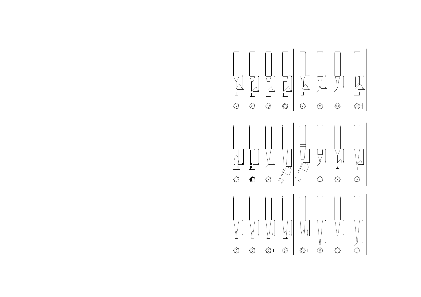
3. Extending Tip Life
1) Tin the tip before and after each use. This protects the tip from oxidizing,
and prolongs the tip's life.
2) Do the job at the lowest temperature. Lower temperatures decrease tip
oxidation and are easier on the components being joined.
3) Use fine point tips only when necessary. The plating on fine precision tips
is less durable than the plating on blunter tips.
4) Do not use the tip as a prying tool. Bending the tip can cause the plating to
crack, shortening tip life.
5) Use the minimum activation flux necessary to do the job. Higher activation
flux is more corrosive to the tip plating.
6) Extend tip life by switching the system off when not in use.
7) Don‟t apply pressure to the tip. More pressure does not equal more heat. To
improve heat transfer, use solder to form a thermal bridge between the tip
and the solder joint.
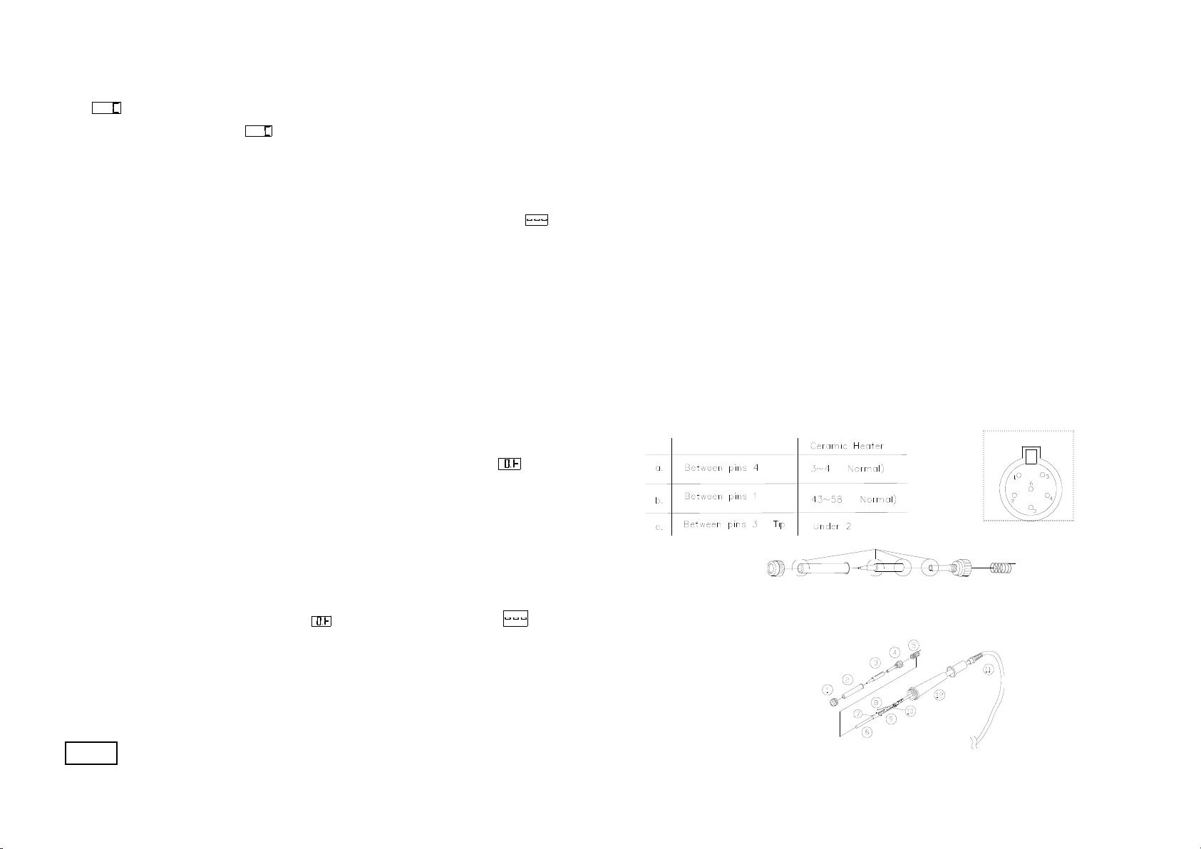
9. Error Messages
Various error messages will be display when there is a problem with the unit. If
the following message is displayed, see the trouble-shooting guide.
Sensor Error: If there is a possibility of a failure in the sensor or
anywhere in the sensor circuit, “S-E” will be displayed
and power to the soldering iron will be cut off.
previous password”.
3. After inputting the three digits, press “*”key and the display shows . At
the time, it must repeat the above steps to input the new password again.
4. If the password is the same as the next, the new password can be changed
successful. The new password is stored into the internal memory. If the
password is not the same as the next, and the display window shows ,
the station will need to rewrite new password. The changing of password is
finished until the lately two passwords are identical.
Note: The word of password is 0 to 9, ten digits. If not, the changed
password is unsuccessful.
6. Calibrating the temperature
The soldering iron should be recalibrated after changing the iron or replacing the
heating element or tip. The unit is designed with digital type of calibration and
key adjust temperature
Method of recalibrating temperature: Use the thermometer to calibrate.
1. Set the unit‟s temperature to a certain value.
2. When the temperature stabilizes, measure the tip‟s temperature with
thermometer and write down the reading.
3. Press “ *”key not loose and press the “UP” and “DOWN” keys
simultaneously, the soldering station enters into calibration mode.
4. At the moment, the hundred-digit of LED display temperature is flashing.
Press the “UP” and “DOWN” keys to select the value and press the “*” key
to select the digit. Press “*” key after inputting the reading. Here, the
calibration operation has been finished.
5. If the temperature still has deflection, you can repeat calibration in
accordance with above steps.
* Recommend using the 191/192 thermometer measuring the tip temperature.
* It will not be able to calibrate if the unit is locked by password and you must
input the right password.
Page 7
S - E
Page 10

7. To select a correct tip for a solder application
1. Pick a tip that maximizes contact area between the tip and solder Joint.
Maximizing contact area gives the most efficient heat transfer, allowing
operators to produce high quality solder joints quickly.
2. Pick a tip that allows good access to the solder joint. Shorter tip lengths allow
more precise control. Longer or angled may be needed for soldering densely
populated boards.
8. Tip Care and Use
8.1 Tip’s usage
1. High soldering temperatures can degrade the tip. Use the lowest possible
soldering temperature. The excellent thermal recovery characteristics ensure
efficient and effective soldering event at low temperatures. This also protects
the soldered items from thermal damage.
2. Clean the tip regularly with a cleaning sponge. Because oxides and
carbides from the solder and flux can form impurities on the tip, these
impurities can result in defective joints or reduce the tip's heat conductivity.
3. When using the soldering iron continuously, be sure to loosen the tip and
remove all oxides at least once a week. This helps prevent seizure and
reduction of the tip temperature.
4. Never leave the soldering iron at high temperature for a long period of time,
as the tip's solder plating will become covered with oxide, which can greatly
reduce the tip's heat conductivity.
5. After using, wipe the tip and coat the tip with fresh solder. It helps to prevent
tip from oxidation.
8.2 Tip’s maintenance
1. Inspect and clean the tip
1) Set the temperature to a certain temperature , such as 250℃or 280℃.
2) When the temperature stabilizes, clean the tip with the cleaning sponge and check
the condition of the tip.
3) If there is black oxide on the solder-plated portion of the tip, apply new
solder (containing flux) and wipe the tip on the cleaning sponge. Repeat
until the oxide is completely remove. Coat with new solder to protects
the tip from oxidation and prolongs the life of the tip.
4) If the tip is deformed or heavily eroded, replace it with a new one.
Caution: Never file the tip to remove oxide.
2. Tin with the tip
1) Why a “detinned”tip fails to work?
A detinned tip is one, which cannot wet with solder. This exposes the
plating to oxidation and degrades the heat transfer efficiency of the tip.
2) Detinning is caused by the following reasons:
①Failure to keep the tip covered with fresh solder during idling periods.
②High tip temperatures.
③Lack of sufficient flux in soldering operations.
④Wiping the tip on dirty or dry sponges and rags. (Always use a clean,
wet, industrial grade, sulfur-free sponge.)
⑤Impurities in the solder, iron plating, or on the surfaces to be soldered.
3) Restore a detinned tip
①Remove the tip from the solder handle after the tip cooling down.
Page 8
Page 9
Table of contents
Other VECTECH Soldering Gun manuals