VECTECH S8 User manual
VECTECH S8 Soldering Station
Instruction Manual
Thank you for purchasing our products. Please keep
the instruction manual properly for future reference.


Contents
1. Safety Instructions............................................................................... 1
2. Overview................................................................................................2
3. Product Characteristics.......................................................................2
4. Product Specifications.........................................................................3
5. Functional Descriptions.......................................................................4
5.1. Dimensions................................................................................ 4
5.2. Part Descriptions.......................................................................4
5.3. Key Descriptions.......................................................................5
5.4. Function Descriptions of the Main Interface........................ 5
6. Use of Holder and Sponge................................................................. 6
7. Connection............................................................................................ 7
8. Turn On/Off............................................................................................7
9. Temperature Settings.......................................................................... 7
10. Menu Settings.....................................................................................8
10.1. Channel Temperature Settings.............................................8
10.2. Temperature Unit Setting...................................................... 9
10.3. Sleeping Time Setting............................................................9
10.4. Close Time Setting...............................................................10
10.5. Display Setting......................................................................10
10.6. Temperature Limit Alarm Setting....................................... 10
10.7. Password Setting..................................................................11
10.8. ESD Test Settings................................................................ 12
10.9. Soldering Hint Settings........................................................12
10.10. Key tone Settings...............................................................12
10.11. Patterns............................................................................... 13
10.12. Language Settings.............................................................13

10.13. Tip selection........................................................................ 14
11. Temperature Calibration................................................................. 14
12.Maintenance of Tips......................................................................... 15
13.Selection of Tips................................................................................16
14.Troubleshooting.................................................................................17
1
1.Safety Instructions
CAUTION
During the installation and use of this product, all electrical safety
regulations of the country and regions must be strictly observed.
The power supply must be disconnected when disassembling the
product. Do not operate with power on.
If the product does not work properly, please contact the supplier or
our company, and do not disassemble or change the product in any
way. We are not responsible for any problems caused by unauthorized
maintenance or modification.
WARNING
Don't install the product in a place where the surface is easy to shake
or be impacted, as it may damage the product.
Don't place the product in places where it may be exposed to rain or
moisture.
The product should be used away from places where there is
magnetic interference.
Don't use in flammable and explosive environments.
Pay attention to the air outlet and its surroundings. High temperature
operation, be careful of burns.
Don't knock workbench with the soldering pencil to remove residual
flux, which may seriously damage the soldering pencil.
When the soldering pencil is not in use, please turn off the power to
prolong its life.
Please unplug the power cord when the product is not used for a long
time.

2
2.Overview
This product is an intelligent precision soldering station. It adopts LCD
display and mechanical buttons, making it more comfortable to use.
Accurate and sensitive temperature sensor , fast heating and thermal
recovery speed, compact soldering tip.
3.Product Characteristics
Can preset process parameter in three channels, more practical.
Celsius and Fahrenheit interchangeable.
ESD design, ESD test function available.
Resistance type heating element, integrated plug-in soldering tip.
Only 3S for temperature rise from room temperature to 300℃, rapid
heating.
Two interface options for digital curves.
Soldering tip vibrating when reaching the setting temperature.
3
4.Product Specifications
Product type
S8
Display
LCD
Power consumption
150W(Max)
Voltage
AC 110V/220V
Temperature range
100℃~450℃/ 212℉~842℉
Temperature stability
±2℃(No load)
Ambient temperature
0~40℃
Tip to ground potential
<2mV
Tip to ground resistance
<2Ω
Dimensions (L×W×H)
169.6*137*114.5mm
Weight
About 2.9 Kg

4
5.Functional Descriptions
5.1.Dimensions
Unit:mm
5.2.Part Descriptions
NO.
Part Descriptions
1
Main unit
2
Handle
3
Holder

5
5.3.Key Descriptions
5.4.Function Descriptions of the Main Interface
Key
Function Descriptions
1/2/3
1. Press on the main interface to switch between CH1, CH2
and CH3
2. Press “2” and “3” keys at the same time on the main
interface to enter the menu setting interface. Press “1 “and
“3” keys at the same time to enter the temperature
calibration interface
3. Press “1” key on the menu setting interface to turn the
page, and press“2” key to save,and“3” key to return
+
1.Main interface: temperature up
2.Setting interface: page down
-
1. Main interface: temperature down
2. Setting interface: page up
6
6. Use of Holder and Sponge
1) Wet the cleaning sponge and then squeeze it dry.
2) Place the sponge into the groove of the holder base.
3) In the process of use, if the sponge becomes dry, please add water
appropriately.
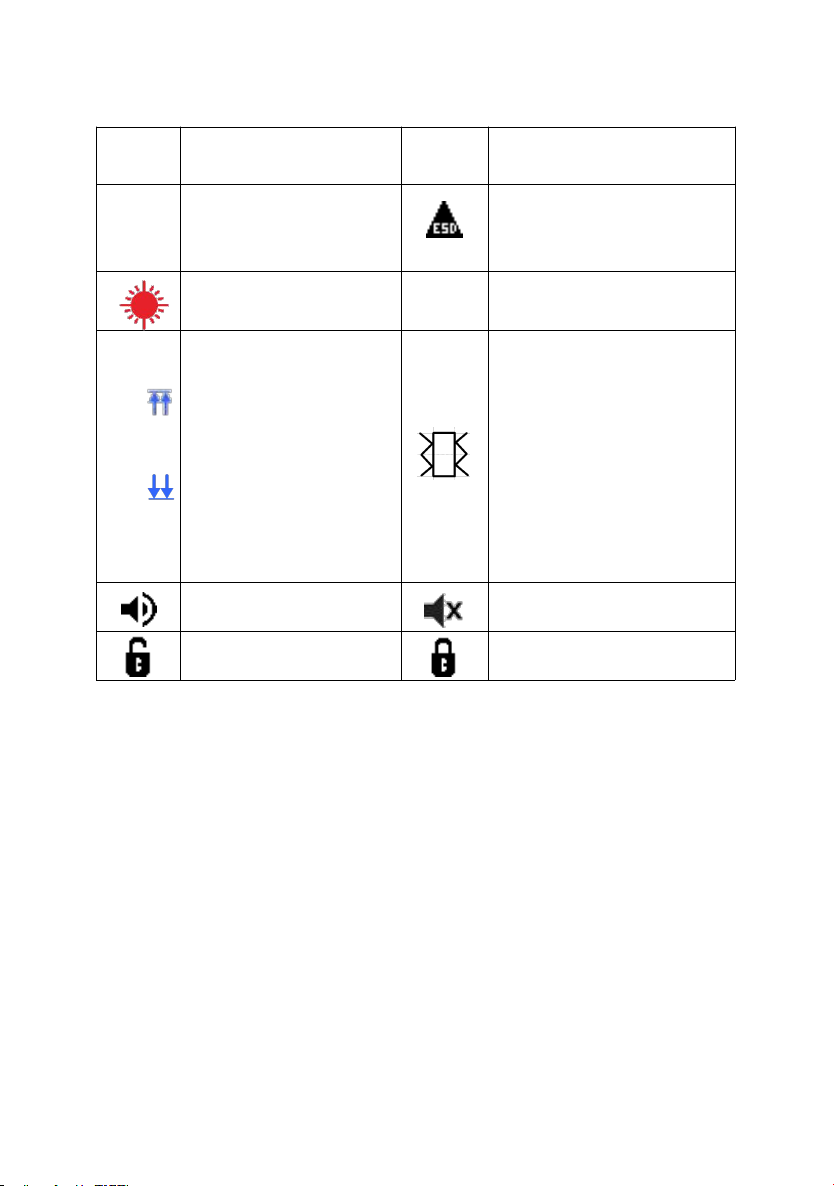
Symbols
Descriptions
Symbols
Descriptions
CH0
Temporary channel
Black indicates ESD OFF,
Red indicates ESD ON
Heating state
℃/℉
℃/℉ interchangeable
1
2〓
3
1.Indicates the heating
state
2.Indicates that the set
temperature is reached
3.Indicates the cooling
state
Blue indicates the soldering
prompt is ON.
Red indicates the handle is
vibrating.
Black indicates the soldering
prompt is OFF.
Buzzer on
Buzzer off
No password lock
Password lock
Table of contents
Other VECTECH Soldering Gun manuals


Popular Soldering Gun manuals by other brands


Velleman
Velleman HRJA151 user manual

Weller
Weller WSM 1 operating instructions

Vishay Precision Group
Vishay Precision Group Micro-Measurements Mark V Operating and maintaining

ersa
ersa i-CON 1V quick guide

Hakko Electronics
Hakko Electronics FX-100 instruction manual

Weller
Weller WAD 101 operating instructions


