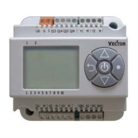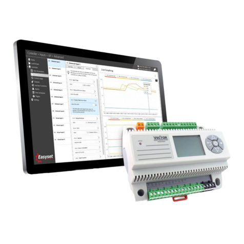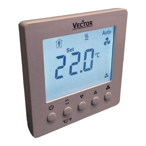
TCI-C Universal Controller
CONTROL CHARACTERISTICS
compensation
compensation
Summer–winter compensation active on loop 1
Control loops (Parameters 1L00—1L08, 2L00—2L08; 1A00, 2A00, 1D01, 2D01)
TCI-C11 and TCI-C13 have 1 control loop (labeled 1L). TCI-C22 has 2 independent control loops (1L and 2L). Each control
loop may utilize 6 binary (on/off) and 2 PID control sequences. Control loops and sequences are activated when output
parameters are defined.
Standby set point shift (Parameters 1L07, 2L07)
This function shifts the set point for STANDBY (unoccupied) mode. The heating set point is reduced and the cooling set point
increased by a value set in parameters
Dead zone span (Parameters 1L08, 2L08)
Dead zone span lies between the heating and the cooling set point. It is selectable withparameters. A negative dead zone is
not possible.
Minimum and maximum set point (Parameters 1L01—1L04, 2L01—2L04)
The adjustable range of heating and cooling set points may be chosen individually
Cascade control (Parameters 1L06, 2L06)
TCI-C22 features 2 independent control loops with available cascade function. In cascade control the output of the primary
loop determines the set point of the secondary loop. The output of the set-point-providing primary loop is spanned between
the min. and max. set point limits of the secondary loop. Select the cascade parameter on Loop 2 (2L06) to make Loop 1
primary. Select the cascade parameter on Loop 1 (1L06) to make Loop 2 primary. In the secondary loop you choose to
cascade with 1) the reverse sequence, 2) the direct sequence, or 3) both the reverse and the direct sequence of the primary
loop. (Heating is a reverse sequence because output from the controller rises as temperature lowers. Cooling is a direct
sequence because output from the controller rises as temperature rises.) The following example of cascade control represents
a typical pressure independent VAV application where the temperature control loop (primary) determines the set point of the
air flow control loop (secondary).
Secondary Loop Airflow (Loop 2 - 2L) Primary Loop Temperature (Loop 1 - 1L)
Parameter 2L06=2
Cascade with reverse sequence of primary loop only Output 1L spanned between min. and max. set point limits
of 2L when 1L is reverse sequence.
Min. set point heating is 20% (2L01
Max. set point heating is 100% (2L02) Output of 1L is spanned between 20% and 100%.
When 1L output is 50%, 2L set point is 55%
When 1L output is direct (cooling) sequence, set point 2L is fixed to min. cooling set point limit (2L03)
Set point compensation – Set point reset (Parameters 1L05, 2L05 to enable; FU00—FU07 to configure input)
Shift the set point either towards the set
point minimum (negative shift) or the set
point maximum (positive shift)
depending on an external input signal.
This is done to compensate the set point
due to a change in the environment. It is
most commonly applied to outside
temperature. Summer-winter
compensation is activated through
parameters 1L05 or 2L05. Parameter
FU00 selects the compensation input
signal, either external temperature or
analog input. Winter compensation is
active when outside temperature drops
below the upper limit of winter
compensation (FU03). Depending on
parameter FU01, the set point is shifted
towards the heating set point min. or
max. Maximum compensation is reached
when the temperature reaches the lower limit (FU02). The actual set point will in this case be equal to the min. heating set
point limit for a negative shift or the max. set point limit for a positive shift. Summer compensation is active when the outside
temperature exceeds the lower limit for summer compensation (FU05). Depending on parameter FU04, the set point is now
shifted towards the cooling set point min. or max. It reaches its max. when the temperature equals the upper limit (FU06).
Doc: 70-07-0123, V1.2, Date: 20101022 Subject to alteration ©Vector Controls GmbH, Switzerland Page 6
