Vega VEGAFLEX 67 User manual

Operating Instructions
VEGAFLEX 67
400 °C/160 bar
Profibus PA

Contents
1About this document
1.1Function ............................. 4
1.2Target group .......................... 4
1.3Symbolism used ....................... 4
2For your safety
2.1Authorised personnel .................... 5
2.2Appropriate use........................ 5
2.3Warning about misuse ................... 5
2.4CE conformity ......................... 5
2.5Fulfilling NAMUR recommendations ......... 6
2.6Safety instructions for Ex areas ............ 6
2.7Manufacturer declaration ................. 6
2.8Environmental instructions ................ 7
3Product description
3.1Configuration.......................... 9
3.2Principle of operation.................... 10
3.3Operation ............................ 12
3.4Storage and transport ................... 13
4Mounting
4.1General instructions..................... 14
4.2Mounting instructions.................... 15
5Connecting to voltage supply
5.1Preparing the connection ................. 18
5.2Connection steps Instrument housing ........ 19
5.3Wiring plan,single chamber housing......... 20
5.4Wiring plan,double chamber housing ........ 22
5.5Wiring plan,version IP 66/IP 68,1bar ....... 24
6Setup with the indicating and adjustment module
PLICSCOM
6.1Short description ....................... 25
6.2Insert the indicating and adjustment module ... 25
6.3Adjustment system ..................... 27
6.4Setup procedure ....................... 28
6.5Menu schematic ....................... 35
7Setup with PACTware™and other adjustment
programs
7.1Connecting the PC ..................... 37
2VEGAFLEX 67 -Profibus PA
Contents
32768-EN-061227

7.2Parameter adjustment with PACTware™...... 37
7.3Parameter adjustment with PDM............ 38
7.4Saving the parameter adjustment data ....... 38
8Maintenance and fault rectification
8.1Maintenance .......................... 39
8.2Rectify faults .......................... 39
8.3Exchange of the electronics module ......... 41
8.4Instrument repair ....................... 42
9Dismounting
9.1Dismounting procedure .................. 43
9.2Disposal ............................. 43
10 Supplement
10.1Technical data......................... 44
10.2Profibus PA........................... 53
10.3Dimensions ........................... 58
10.4Industrial property rights.................. 61
10.5Trademark ........................... 61
Supplementary operating instructions manuals
Information:
VEGAFLEX 67 is available in different versions.Depending on
the selected version,supplementary operating instructions
manuals may also come with the shipment.The supplemen-
tary operating instructions manuals are listed in section
"Product description.
Operating instructions manuals for accessories and
replacement parts
Tip:
To ensure reliable setup and operation of your VEGAFLEX 67,
we offer accessories and replacement parts.The associated
documents are:
lOperating instructions manual "External indicating and
adjustment unit VEGADIS 61"
lOperating instructions manual "Oscillator VEGAFLEX
series 60"
lSupplementary instructions manual "Flanges according to
DIN-EN-ASME-JIS"
VEGAFLEX 67 -Profibus PA 3
Contents
32768-EN-061227

1About this document
1.1Function
This operating instructions manual has all the information you
need for quick setup and safe operation.Please read this
manual before you start setup.
1.2Target group
This operating instructions manual is directed to trained,
qualified personnel.The contents of this manual should be
made available to these personnel and put into practice by
them.
1.3Symbolism used
Information,tip,note
This symbol indicates helpful additional information.
Caution:If this warning is ignored,faults or
malfunctions can result.
Warning:If this warning is ignored,injury to persons and/or
serious damage to the instrument can result.
Danger:If this warning is ignored,serious injury to persons
and/or destruction of the instrument can result.
Ex applications
This symbol indicates special instructions for Ex applications.
lList
The dot set in front indicates a list with no implied sequence.
àAction
This arrow indicates a single action.
1Sequence
Numbers set in front indicate successive steps in a procedure.
4VEGAFLEX 67 -Profibus PA
About this document
32768-EN-061227

2For your safety
2.1Authorised personnel
All operations described in this operating instructions manual
must be carried out only by trained specialist personnel
authorised by the operator.For safety and warranty reasons,
any internal work on the instruments must be carried out only
by personnel authorised by the manufacturer.
2.2Appropriate use
VEGAFLEX 67 is a sensor for continuous interface measure-
ment in liquids.
Detailed information on the application range of VEGAFLEX 67
is available in chapter "Product description".
2.3Warning about misuse
Inappropriate or incorrect use of the instrument can give rise to
application-specific hazards,e.g.vessel overfill or damage to
system components through incorrect mounting or adjustment.
2.4General safety instructions
VEGAFLEX 67 is a high-tech instrument requiring the strict
observance of standard regulations and guidelines.The user
must take note of the safety instructions in this operating
instructions manual,the country-specific installation standards
(e.g.the VDE regulations in Germany)as well as all prevailing
safety regulations and accident prevention rules.
2.5CE conformity
VEGAFLEX 67 is in CE conformity with EMC (89/336/EWG)
and LVD (73/23/EWG).
Conformity has been judged according to the following
standards:
lEMC:
-Emission EN 61326:2004 (class B)
-Susceptibility EN 61326:2004 including supplement A
lLVD:EN 61010-1:2001
VEGAFLEX 67 -Profibus PA 5
For your safety
32768-EN-061227

2.6Fulfilling NAMUR recommendations
With regard to interference resistance and interference
emission,VEGAFLEX 67 fulfils NAMUR recommendation
NE 21.
VEGAFLEX 67 and its indicating and adjustment components
fulfill NAMUR recommendation NE 53 in respect to compat-
ibility.VEGA instruments are generally upward and downward
compatible:
lSensor software to DTM VEGAFLEX 67 HART,PA or FF
lDTM VEGAFLEX 67 for adjustment software PACTware™
lIndicating and adjustment module for sensor software
The parameter adjustment of the basic sensor functions is
independent of the software version.The range of available
functions depends on the respective software version of the
individual components.
The software version of VEGAFLEX 67 can be determined as
follows:
lvia PACTware™
lon the type label of the electronics
lvia the indicating and adjustment module
You can view all software histories on our website www.vega.
com.Make use of this advantage and get registered for update
information via e-mail.
2.7Safety instructions for Exareas
Please note the Ex-specific safety information for installation
and operation in Ex areas.These safety instructions are part of
the operating instructions manual and come with the Ex-
approved instruments.
2.8Manufacturer declaration
In conformity with DIN EN 60079-14/1998,para.5.2.3,point
c1,the probe VEGAFLEX 67 is suitable for use in zone 2.
The operator must use the instrument as it was intended to be
used and follow the specifications of the following documents:
lthis operating instructions manual
lthis manufacturer declaration (24628)
lthe applicable installation regulations
6VEGAFLEX 67 -Profibus PA
For your safety
32768-EN-061227

Max.increase of the surface temperature during operation:
15 K(individual components in the instrument)
With an ambient temperature of 70 °C(158 °F)on the housing
and a process temperature of 70 °C(158 °F), the max.ambient
temperature during operation is 85 °C(185 °F).
Measures to maintain explosion protection during operation:
lOperate the instrument in the range of the specified
electrical limit values.Permissible supply voltage:see
"Technical data"
lMount and operate the instrument in such a way that no
ignition danger is expected by electrostatic charges.The
process fitting,the plastic-coated/covered probe part or the
housing are made of electrically non-conductive plastic
(depending on the version).
lMake sure that the seal is mounted correctly between
lower part of the housing and cover.Screw the cover on
tightly.
lMake sure there is no explosive atmosphere present if you
intend to operate the instrument with opened cover
lMake sure that the cable gland is tight and strain-relieved.
The outer diameter of the connection cable must be
adapted to the cable gland.Tighten the pressure screw of
the cable gland carefully.
lCover unused openings for cable glands tightly
lMount the instrument in such a way that the sensor cannot
touch the vessel wall or vessel installations.Keep in mind
the influence of product movement in the vessel.
lThe surface temperature of the housing must not exceed
the ignition temperature of the surrounding explosive
atmosphere
This instrument was assessed by a person who fulfils the DIN
EN 60079-14 requirements.
2.9Environmental instructions
Protection of the environment is one of our most important
duties.That is why we have introduced an environment
management system with the goal of continuously improving
company environmental protection.The environment man-
agement system is certified according to DIN EN ISO 14001.
Please help us fulfil this obligation by observing the environ-
mental instructions in this manual:
lChapter "Storage and transport"
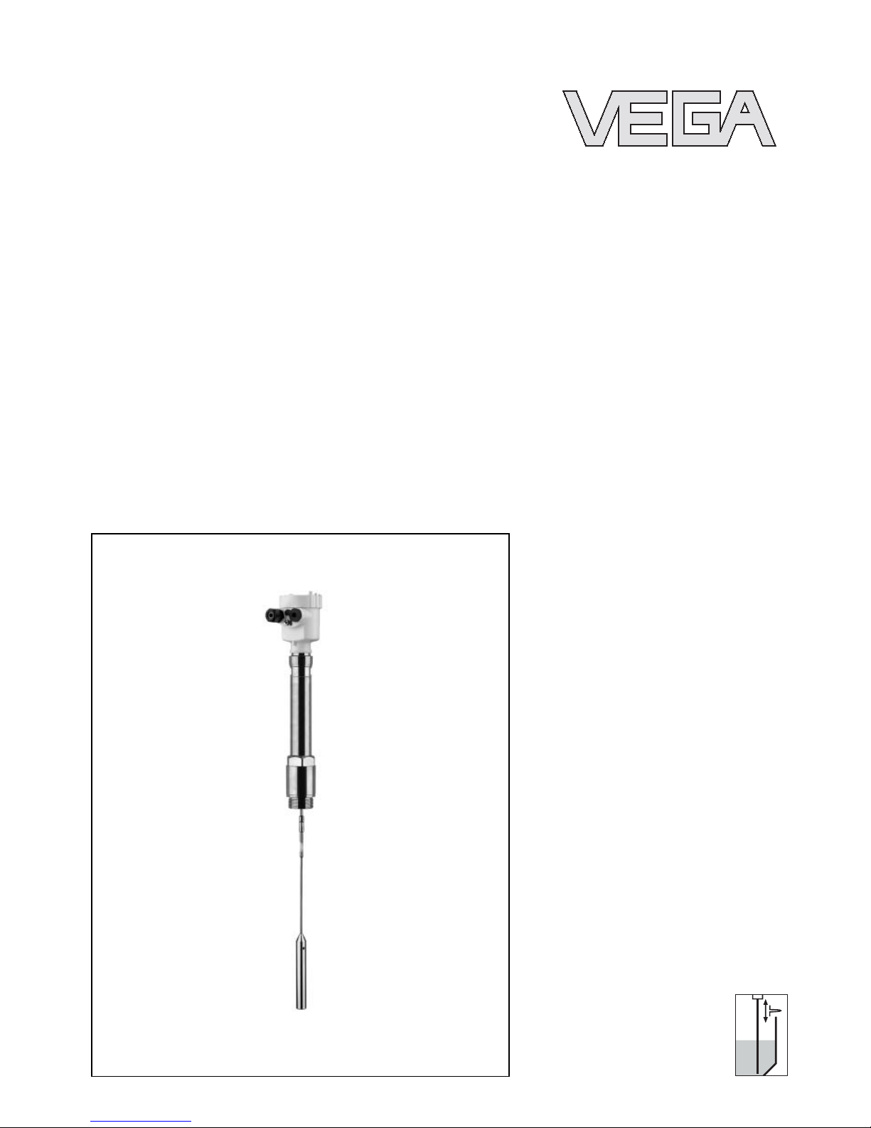
VEGAFLEX 67 -Profibus PA 7
For your safety
32768-EN-061227

lChapter "Disposal"
8VEGAFLEX 67 -Profibus PA
For your safety
32768-EN-061227

3Product description
3.1Configuration
The scope of delivery encompasses:
lVEGAFLEX 67 level sensor
lDocumentation
-this operating instructions manual
-Safety Manual "Functional safety according to
IEC 61508/IEC 61511 (SIL)"
-Operating instructions manual "Indicating and adjust-
ment module"(optional)
-Supplementary instructions manual "Heating for indi-
cating and adjustment module"(optional)
-Supplementary instructions manual "Plug connector for
continuously measuring sensors"(optional)
-Ex-specific"Safety instructions"(with Ex-versions)
-if necessary,further certificates
VEGAFLEX 67 consists of the following components:
lProcess fitting with probe
lHousing with electronics
lHousing cover,optionally available with indicating and
adjustment module
Scope of delivery
Components
VEGAFLEX 67 -Profibus PA 9
Product description
32768-EN-061227

1
2
3
Fig.1:VEGAFLEX 67 in cable version with plastic housing
1Housing cover with integrated PLICSCOM (optional)
2Housing with electronics
3Process fitting
3.2Principle of operation
VEGAFLEX 67 is a level sensor with coax,rod or cable probe
for continuous interface measurment.
It is designed for industrial use in all areas of process
technology and can be used in liquids.
High frequency microwave impulses are guided along a steel
cable or rod or a rod inside a steel tube.When reaching the
product surface,a part of the microwave impulses is reflected.
The other part passes the upper product and is reflected a
second time by the interface.The running times to the two
product layers are processed by the instrument.
Upper medium (L2)
lThe upper medium must not be conductive
Area of application
Functional principle
Prerequisites for interface
measurement
10 VEGAFLEX 67 -Profibus PA
Product description
32768-EN-061227

lThe dielectric value of the upper medium must be known
(input necessary). Min.dielectric values:Rod version 1.7,
coax version 1.4.You will find a list of the dielectric values
on our homepage:www.vega.com.
lThe composition of the upper medium must be stable,no
varying products or mixtures
lThe upper medium must be homogeneous,no stratifica-
tions within the medium
lMin.thickness of the upper medium 100 mm
lClear separation from the lower medium,no emulsion
phase,no mull layer
lIf possible,no foam on the surface
Lower medium (L1)
lThe dielectric value must be 10 higher than the dielectric
value of the upper medium,preferably electrically con-
ductive.Example:upper medium dielectric value 2,lower
medium at least dielectric value 12
TS
d1
h1
h2
d2
1
L2
L1
Fig.2:Interface measurement
1Reference plane
d1Distance to the interface
d2Distance to the level
TS Thickness of the upper medium (d1-d2)
h1Height -Interface
h2Height -Level
L1Lower medium
L2Upper medium
The interface is directly processed by the sensor and
outputted as digital output signal.
The display of PLICSCOM and PACTware™outputs the
distance to the interface (d1)in m(d).
Output signal
VEGAFLEX 67 -Profibus PA 11
Product description
32768-EN-061227

Power supply via the Profibus DP/PA segment coupler or
VEGALOG 571 EP cards.Atwo-wire cable according to
Profibus specification serves as carrier of both power and
digital data signals for multiple sensors.The instrument profile
of VEGAFLEX 67 corresponds to profile specification version
3.0.
The GSD (instrument master files)and bitmap files necessary
for planning your Profibus-DP-(PA)communication network
are available from the download section on the VEGA
homepage www.vega.com under "Services -Downloads -
Software -Profibus".There you can also find the appropriate
certificates.InaPDM environment,an EDD (Electronic Device
Description)is also required to enable the full range of sensor
functions (also available as a download).ACDwith the
appropriate files can be ordered via e-mail under info@de.
vega.com or by phone from one of the VEGA agencies under
the order number "DRIVER.S".
The backlight of the indicating and adjustment module is
powered by the sensor.Requirement is a certain height of the
supply voltage.
The data for power supply are stated in chapter "Technical
data"in the "Supplement".
This function is for instruments with StEx,WHG or ship
approval as well as country-specificapprovals such as those
according to FM or CSA,available at a later date.
The optional heating requires its own power supply.You can
find further details in the supplementary instructions manual
"Heating for indicating and adjustment module".
This function is generally not available for approved instru-
ments.
3.3Operation
VEGAFLEX 67 can be adjusted with different adjustment
media:
lwith indicating and adjustment module
lwith the suitable VEGA DTM in conjunction with an
adjustment software according to the FDT/DTM standard,
e.g.PACTware™and PC
lthe Simatic adjustment program PDM
Power supply and bus com-
munication
GSD/EDD
12 VEGAFLEX 67 -Profibus PA
Product description
32768-EN-061227

The entered parameters are generally saved in VEGAFLEX
67,optionally also in the indicating and adjustment module or
in PACTware™.
3.4Storage and transport
Your instrument was protected by packaging during transport.
Its capacity to handle normal loads during transport is assured
by a test according to DIN EN 24180.
The packaging of standard instruments consists of environ-
ment-friendly,recyclable cardboard.For special versions,PE
foam or PE foil is also used.Dispose of the packaging material
via specialised recycling companies.
lStorage and transport temperature see "Supplement -
Technical data -Ambient conditions"
lRelative humidity 20 …85 %
Packaging
Storage and transport tem-
perature
VEGAFLEX 67 -Profibus PA 13
Product description
32768-EN-061227

4Mounting
4.1General instructions
Select an installation position you can easily reach for
mounting and connecting as well as later retrofitting of an
indicating and adjustment module.The housing can be rotated
by 330°without the use of any tools.You can also install the
indicating and adjustment module in four different positions
(each displaced by 90°).
Before beginning with the welding work,remove the oscillator
out of the sensor.By doing this,you avoid damages ont he
electrode due to inductive couplings.
The housing of the threaded versions must not be used to
screw the instrument in!Applying tightening force on the
housing can damage its rotational mechanical parts.
Use the hexagon for screwing in.
Use the recommended cables (see chapter "Connecting to
power supply")and tighten the cable gland.
You can give your VEGAFLEX 67 additional protection against
moisture penetration by leading the connection cable down-
ward in front of the cable entry.Rain and condensation water
can thus drain off.This applies mainly to mounting outdoors,in
areas where moisture is expected (e.g.by cleaning processes)
or on cooled or heated vessels.
Fig.3:Measures against moisture penetration
The reference plane for the measuring range of the sensors is
the seal surface of the thread or flange.
Installation position
Welding work
Handling
Moisture
Measuring range
14 VEGAFLEX 67 -Profibus PA
Mounting
32768-EN-061227

Keep in mind that a min.distance must be maintained below
the reference plane and possibly also at the end of the probe -
measurement in these areas is not possible (dead zone). Keep
in mind that the cable length cannot be used up to the end
because measurement in the area of the gravity weigh is not
possible.These min.distances are listed in chapter "Technical
data"in the "Supplement".
The process fitting must be sealed if there is gauge or low
pressure in the vessel.Before use,check if the seal material is
resistant against the measured product and the process
temperature.
The max.permissible pressure is stated in chapter "Technical
data"in the "Supplement"or on the type label of the sensor.
4.2Mounting instructions
Mount VEGAFLEX 67 in such a way that the probe does not
touch any installations or the vessel wall during installation.
Mount cable and rod versions of VEGAFLEX 67 in such a way
that the distance to vessel installations or the vessel wall is at
least 300 mm (11.8in).
During operation,the probe must not touch any installations or
the vessel wall.If necessary,fasten the probe end.
In vessels with conical bottom it can be advantageous to
mount the sensor in the center of the vessel,as measurement
is then possible down to the lowest point of the bottom.When
using the cable version,keep in mind that measurement down
to the end of the probe is not possible.The exact value of the
min.distance (lower dead zone)is stated in chapter "Technical
data"in the "Supplement".
Pressure
Installation position
VEGAFLEX 67 -Profibus PA 15
Mounting
32768-EN-061227

Fig.4:Vessel with conical bottom
Make sure that the probe is not subjected to strong lateral
forces.Mount VEGAFLEX 67 at a position in the vessel where
no disturbances,e.g.from filling openings,agitators,etc., can
occur.
Fig.5:Lateral load
Excessive system vibration or shocks,e.g.caused by agitators
or turbulence in the vessel (e.g.from fluidisation)can cause
the coax probe of VEGAFLEX 67 to vibrate in resonance.
Should a coax probe of more than 1m(3.3in)length should be
used,you can provide a suitable support or guy directly above
the end of the probe to stabilise it.
Inflowing medium
16 VEGAFLEX 67 -Profibus PA
Mounting
32768-EN-061227

VEGAFLEX 67 should be integrated in the vessel installation.
This prevents the electronics from strong heating by heat
radiation.
Make sure that in heated vessels the permissible ambient
temperature on the housing is not exceeded.The permissible
ambient temperature is stated in chapter "Technical data"
under "Ambient conditions".
1
2
Fig.6:Vessel with heat insulation
1Heat insulation
2Ambient temperature on the housing
Heat insulation
VEGAFLEX 67 -Profibus PA 17
Mounting
32768-EN-061227

5Connecting to voltage supply
5.1Preparing the connection
Generally note the following safety instructions:
lConnect only in the complete absence of line voltage
lIf overvoltage surges are expected,overvoltage arresters
should be installed according to Profibus specification
In hazardous areas you should take note of the appropriate
regulations,conformity and type approval certificates of the
sensors and power supply units.
Power is supplied via a Profibus DP/PA segment coupler or a
VEGALOG 571 EP input card.The power supply range can
differ depending on the instrument version.
The data for power supply are stated in chapter "Technical
data"in the "Supplement".
VEGAFLEX 67 is connected with screened cable according to
the Profibus specification.Power supply and digital bus signal
are carried over the same two-wire connection cable.
An outer cable diameter of 5…9mm ensures the seal effect
of the cable entry.
Please make sure that your installation is carried out according
to the Profibus specification.In particular,make sure that the
termination of the bus is done with appropriate terminating
resistors.
OnVEGAFLEX 67 with cable gland ½NPT and plastic
housing,a metal ½" threaded insert is moulded in the plastic
housing.
Caution:
No grease should be used when screwing the NPT cable
gland or steel tube into the threaded insert.Standard grease
can contain additives affecting the connection between
threaded insert and housing.This will influence the stability of
the connection and the tightness of the housing.
In systems with potential equalisation,connect the cable
screen directly to ground potential at the power supply unit,in
the connection box and at the sensor.The screen in the sensor
Note safety instructions
Take note of safety
instructions for Ex
applications
Select power supply
Selecting connection cable
Cable gland ½NPT
Cable screening and ground-
ing
18 VEGAFLEX 67 -Profibus PA
Connecting to voltage supply
32768-EN-061227

must be connected directly to the internal ground terminal.The
ground terminal outside on the housing must be connected to
the potential equalisation (low impedance).
In systems without potential equalisation,connect the cable
screen directly to ground potential at the power supply unit and
at the sensor.In the connection box or T-distributor,the screen
of the short stub to the sensor must not be connected to
ground potential or to another cable screen.The cable screens
to the power supply unit and to the next distributor must be
connected to each other and also connected to ground
potential via a ceramic capacitor (e.g.1nF,1500 V). The low
frequency potential equalisation currents are thus suppressed,
but the protective effect against high frequency interference
signals remains.
The total capacitance of the cable and of all capacitors must
not exceed 10 nFin Ex applications.
Take note of the corresponding installation regulations for Ex
applications.In particular,make sure that no potential equal-
isation currents flow over the cable screen.In case of
grounding on both sides this can be achieved by the use of a
capacitor or a separate potential equalisation.
5.2Connection steps Instrument housing
Proceed as follows:
1Unscrew the housing cover
2If an indicating and adjustment module is installed,remove
it by turning it slightly to the left.
3Loosen compression nut of the cable entry
4Remove approx.10 cm (4in)of the cable mantle,strip
approx.1cm (0.4in)insulation from the ends of the
individual wires
5Insert the cable into the sensor through the cable entry
6Lift the opening levers of the terminals with a screwdriver
(see following illustration)
7Insert the wire ends into the open terminals according to
the wiring plan
Select connection
cable for Ex applica-
tions
VEGAFLEX 67 -Profibus PA 19
Connecting to voltage supply
32768-EN-061227

Fig.7:Connection steps 6and 7
8Press down the opening lever of the terminals,you will
hear the terminal spring closing.
9Check the hold of the wires in the terminals by lightly
pulling on them
10 Connect the screen to the internal ground terminal and the
external ground terminal to potential equalisation
11 Tighten the compression nut of the cable entry.The seal
ring must completely encircle the cable
12 Screw the housing cover back on
The electrical connection is finished.
5.3Wiring plan,single chamber housing
The following illustrations apply to the non-Ex as well as to the
Ex ia version.
20 VEGAFLEX 67 -Profibus PA
Connecting to voltage supply
32768-EN-061227
Other manuals for VEGAFLEX 67
1
Table of contents
Other Vega Accessories manuals

Vega
Vega VEGAFLEX 86 User manual

Vega
Vega POINTRAC 31 User manual

Vega
Vega VEGAFLEX 81 User manual

Vega
Vega VEGABAR 82 User manual

Vega
Vega VEGAPULS 62 User manual

Vega
Vega vegaflex 83 User manual

Vega
Vega VEGAPULS 11 User manual

Vega
Vega VEGAPULS 6X User manual

Vega
Vega VEGABAR 28 User manual

Vega
Vega VEGAPULS 69 User manual

Vega
Vega VEGAWAVE 61 Instruction Manual

Vega
Vega VEGAPULS 63 User manual

Vega
Vega VEGADIS 61 User manual

Vega
Vega VEGAFLEX 62 User manual

Vega
Vega VEGAPULS 69 User manual

Vega
Vega SOLITRAC 31 User manual

Vega
Vega VEGADIS 82 User manual

Vega
Vega vegaflex 83 User manual

Vega
Vega VEGABAR 81 User manual

Vega
Vega VEGAPULS 63 User manual