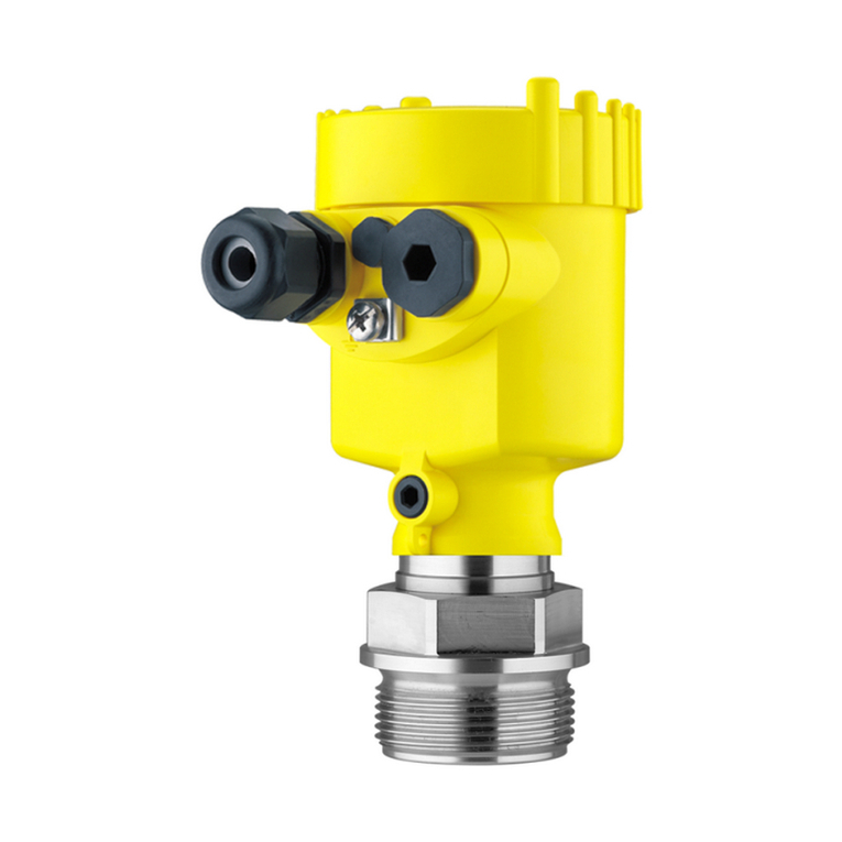
Vega VEGAFLEX FX-E.80H User manual

Operating Instructions
Electronics module
VEGAFLEX 80 series
Document ID: 43656

2
Contents
Electronics module • VEGAFLEX 80 series
43656-EN-170531
Contents
1 About this document
1.1 Function ........................................................................................................................... 3
1.2 Target group ..................................................................................................................... 3
1.3 Symbols used................................................................................................................... 3
2 For your safety
2.1 Authorised personnel ....................................................................................................... 4
2.2 Appropriate use................................................................................................................ 4
2.3 Approvals ......................................................................................................................... 4
2.4 Environmental instructions ............................................................................................... 4
3 Product description
3.1 Conguration.................................................................................................................... 5
3.2 Principle of operation........................................................................................................ 5
3.3 Packaging, transport and storage..................................................................................... 5
4 Mounting
4.1 General instructions ......................................................................................................... 7
4.2 Mounting preparations ..................................................................................................... 7
4.3 Installation procedure....................................................................................................... 7
5 Setup
5.1 Setup preparations........................................................................................................... 9
5.2 Setup steps .................................................................................................................... 12
6 Maintenance
6.1 How to proceed if a repair is necessary.......................................................................... 13
7 Dismount
7.1 Dismounting steps.......................................................................................................... 14
7.2 Disposal ......................................................................................................................... 14
8 Supplement
8.1 Technical data ................................................................................................................ 15
8.2 Industrial property rights................................................................................................. 16
8.3 Trademark ...................................................................................................................... 16
Editing status: 2017-05-05

3
1 About this document
Electronics module • VEGAFLEX 80 series
43656-EN-170531
1 About this document
1.1 Function
This operating instructions manual provides all the information you
need for mounting, connection and setup of the instrument. Further-
morethereareimportantinstructionsformaintenance,faultrectica-
tion, the exchange of parts and the safety of the user. Please read this
information before putting the instrument into operation and keep this
manual accessible in the immediate vicinity of the device.
1.2 Target group
This operating instructions manual is directed to trained specialist
personnel. The contents of this manual should be made available to
these personnel and put into practice by them.
1.3 Symbols used
Information, tip, note
This symbol indicates helpful additional information.
Caution: If this warning is ignored, faults or malfunctions can result.
Warning: If this warning is ignored, injury to persons and/or serious
damage to the instrument can result.
Danger: If this warning is ignored, serious injury to persons and/or
destruction of the instrument can result.
Ex applications
This symbol indicates special instructions for Ex applications.
SIL applications
This symbol indicates instructions for functional safety which must be
taken into account particularly for safety-relevant applications.
• List
The dot set in front indicates a list with no implied sequence.
→ Action
This arrow indicates a single action.
1 Sequence of actions
Numbers set in front indicate successive steps in a procedure.
Battery disposal
This symbol indicates special information about the disposal of bat-
teries and accumulators.

4
2 For your safety
Electronics module • VEGAFLEX 80 series
43656-EN-170531
2 For your safety
2.1 Authorised personnel
All operations described in this operating instructions manual must
be carried out only by trained specialist personnel authorised by the
plant operator.
During work on and with the device the required personal protective
equipment must always be worn.
2.2 Appropriate use
The components described in this manual are replacement compo-
nents for existing sensors.
2.3 Approvals
If the instrument comes with approvals, the associated approval
documents of the sensor must always be noted. They are included
with the delivery but can also be downloaded under "www.vega.com",
"Instrument search" as well as via "Downloads" and "Approvals".
2.4 Environmental instructions
Protection of the environment is one of our most important duties.
That is why we have introduced an environment management system
with the goal of continuously improving company environmental pro-
tection.Theenvironmentmanagementsystemiscertiedaccording
to DIN EN ISO 14001.
Pleasehelpusfullthisobligationbyobservingtheenvironmental
instructions in this manual:
• Chapter "Packaging, transport and storage"
• Chapter "Disposal"

5
3 Product description
Electronics module • VEGAFLEX 80 series
43656-EN-170531
3 Product description
3.1 Conguration
This operating instructions manual applies to electronics modules
with the following hardware and software versions:
• Hardware from 1.0.0
• Software from 1.1.0
The scope of delivery encompasses:
• Electronics module
• Documentation
– This operating instructions manual
– Ex-specic"Safety instructions" (with Ex versions)
– Ifnecessary,furthercerticates
3.2 Principle of operation
The electronics module is suitable for exchange in sensors of the
VEGAFLEX80series.Youcanndinformationoftheavailablever-
sions in chapter "Mounting preparations".
3.3 Packaging, transport and storage
Your instrument was protected by packaging during transport. Its
capacity to handle normal loads during transport is assured by a test
based on ISO 4180.
The packaging of standard instruments consists of environment-
friendly, recyclable cardboard. For special versions, PE foam or PE
foil is also used. Dispose of the packaging material via specialised
recycling companies.
Transport must be carried out in due consideration of the notes on the
transport packaging. Nonobservance of these instructions can cause
damage to the device.
The delivery must be checked for completeness and possible transit
damage immediately at receipt. Ascertained transit damage or con-
cealed defects must be appropriately dealt with.
Up to the time of installation, the packages must be left closed and
stored according to the orientation and storage markings on the
outside.
Unless otherwise indicated, the packages must be stored only under
the following conditions:
• Not in the open
• Dry and dust free
• Not exposed to corrosive media
• Protected against solar radiation
• Avoiding mechanical shock and vibration
Scope of this operating
instructions manual
Scope of delivery
Application area
Packaging
Transport
Transport inspection
Storage

6
3 Product description
Electronics module • VEGAFLEX 80 series
43656-EN-170531
• Storage and transport temperature see chapter "Supplement -
Technical data - Ambient conditions"
• Relative humidity 20 … 85 %
With an instrument weight of more than 18 kg (39.68 lbs) suitable and
approved equipment must be used for lifting and carrying.
Storage and transport
temperature
Lifting and carrying

7
4 Mounting
Electronics module • VEGAFLEX 80 series
43656-EN-170531
4 Mounting
4.1 General instructions
We recommended installing the replacement electronics with the
instrument dismounted and brought to a suitable place, e.g. a work-
shop. If it is not possible to dismount the instrument, the electronics
module can also be installed on site at the measuring point.
Warning:
Switchovoltagesupplybeforestartingtheinstallationprocedure.
The replacement electronics may only be installed when the sensor is
in a de-energised state. Non-observance will damage the electron-
ics!
It is absolutely necessary that the following points are observed with
sensors with Ex approval:
For sensors with Ex approval, make sure that the replacement elec-
tronics module has the same designation as the exchanged electron-
ics module.
Forexample,anelectronicsmodulewithahardwareversion≥2.0.0
mustbeonlyinstalledinasensorwithhardwareversion≥2.0.0.
4.2 Mounting preparations
The electronics modules are mounted in the electronics compartment
and adapted to the respective sensor. First of all, check by means of
the following lists if you are using a suitable electronics module.
• FX-E.80H for version 4 … 20 mA/HART (two-wire/four-wire/Mod-
bus)
• FX-E.80Aforversion4…20mA/HARTwithSILqualication
• FX-E.80PforversionProbusPA
• FX-E.80F for version Foundation Fieldbus
WithSILqualiedinstrument,onlyarespectiveelectronicsmodule
withSILqualicationmustbeused.
ElectronicsmodulesforSILqualiedinstrumentscanonlybeordered
by stating the sensor serial number. Have the sensor serial number
ready when ordering.
4.3 Installation procedure
1
Fig. 1: Single chamber housing
1 Position electronics compartment/Electronics module
Safety during mounting
Ex approval
Assignment

8
4 Mounting
Electronics module • VEGAFLEX 80 series
43656-EN-170531
1
Fig. 2: Double chamber housing
1 Position electronics compartment/Electronics module
Proceed as follows:
1. Switchopowersupply
2. Unscrew the lid of the electronics compartment
3. Remove the terminal blocks according to the operating instruc-
tions manual of the respective sensor
4. Loosen the two holding screws with a screwdriver (Torx size T 10
or slotted screwdriver size 4)
2
555666777888
111222(-)(-)(-)(+)(+)(+)
1
Fig. 3: Loosen the holding screws
1 Electronics module
2 Screws (2 pcs.)
5. Pull the previous electronics out with the dismounting tool.
6. Insert the new electronics module carefully.
7. Screw in the two holding screws and tighten them
8. Attach the terminal blocks according to the operating instructions
manual of the respective sensor
9. Screw the housing lid back on
Theelectronicsexchangeisnownished.
As a rule, an exchange of electronics must be documented internally
if Ex applications are involved.

9
5 Setup
Electronics module • VEGAFLEX 80 series
43656-EN-170531
5 Setup
5.1 Setup preparations
If the electronics module is defective, it can be replaced quickly and
safely by the user.
In general two types of information are necessary for an electronics
exchange
1. Sensor data
These are the data the instrument gets by default during produc-
tion. They include e.g. the sensor type, the probe length, the
language, etc.
2. Parameter data
Thesearetheapplication-specicdatawhichyouhaveentered
ormodiedduringthesensorsetup.Theseareforexamplethe
displayed unit, the measuring point name, the adjustment date,
the damping, etc.
In Ex applications, only instruments and electronics modules with ap-
propriate Ex approval may be used.
WithSILqualiedinstrument,onlyarespectiveelectronicsmodule
withSILqualicationmustbeused.
The electronics modules are adapted to the respective sensor. Hence
the new electronics module must be loaded with the default settings
of the sensor.
The following options are available for restoring the sensor data:
Order the replacement electronics module from the agency serving
you.
When ordering the replacement electronics module, please state the
serial number of the sensor.
The serial numbers are stated on the type label of the instrument,
inside the housing as well as on the delivery note.
Note:
This procedure is only recommended if you have just a few sensors
and, in case of an instrument failure, you have enough time for an
ordering process that can last several days.
By default, the electronics module is loaded with the sensor data (fac-
torysettings)oftheaectedsensor.Rememberthatthiselectronics
module can only be used for the corresponding sensor.
The replacement electronics module is provided with the serial
numberoftheaectedsensor.Beforemounting,checkiftheserial
number on the replacement electronics module and the serial number
of the sensor correspond.
If you ordered the electronics module "ex works", it is ready for pa-
rameterization immediately after installation and connection to power
supply.
Sensor data - ex works

10
5 Setup
Electronics module • VEGAFLEX 80 series
43656-EN-170531
Thenallapplication-specicsettingsmustbeenteredagain.Seethe
following chapter "Setup steps"
Firstofall,youhavetotransferthedevice-specicsensordatatothe
new electronics module.
Under "Instrument search (serial number)" you can download the
specicsensordataasXMLleandthePDFle(onlywithSILquali-
edinstruments)directlyintothesensor.
If you can access the sensor via the adjustment software PACTware
and a DTM, a direct transmission is the easiest and quickest method.
For this you need an Internet access.
1. Start PACTware and connect to the corresponding sensor.
2. Opentheeld"Maintenance" and select"Electronics exchange"
3. After the connection is established, you can choose how the sen-
sor data should be loaded into the sensor.
Choose "Load sensor data from the Internet"
4. Enter in the next step the serial number of your sensor.
Youcanndtheserialnumberoutsideonthetypelabelofthe
instrument and inside the housing.
5. As soon as the sensor data are ready, you can load the data
directly into the sensor.
This procedure lasts approx. 5 minutes.
6. Thenallapplication-specicsettingsmustbeenteredagain.See
the following chapter "Setup steps"
InstrumentswithSILqualication
After the transfer of the sensor data, a check sum is displayed.You
have to verify the correct transmission by means of a check sum. Only
thenistheinstrumentreadyforoperationagainandSILqualied.
The PDF document "SIL electronics exchange check sum certicate"
is opened automatically.
After that, a list of all safety-relevant data is displayed.
Compare the displayed check sum with the data of the PDF docu-
ment.
If the check sums match, the transmission was successful. Record
the comparison of the check sums.
Firstyouhavetotransferthedevice-specicsensordatatothenew
electronics module.
Youcandownloadtheseindividual,device-specicdataofyoursen-
sor from our homepage.
This method is recommended if you have no Internet access on site.
1. Go via our homepage "www.vega.com" to "Instrument search
(serial number)".
2. Enter the serial number of your sensor.
Sensor data - on site via
PA CTw a r e
Sensor data - on site via
download

11
5 Setup
Electronics module • VEGAFLEX 80 series
43656-EN-170531
After entering the instrument serial number, the order data of the
sensor will be displayed.
3. Belowtheorderdata,youcanndunder"Sensor data for service
DTM"theXMLle:"DTMCongurationFile".
ClickwiththerightmousekeytotheleanddownloadthisXML
lewith"Save target under" to your PC.
4. ForinstrumentswithSILqualicationyouhavetodownloadthe
PDF document "SIL electronics exchange check sum certicate"
also from the homepage.
ClickwiththerightmousekeytotheleanddownloadthisPDF
lewith"Save target under" to your PC.
5. ComparetheserialnumberoftheXMLlewiththeserialnumber
of your sensor.
Youcanndtheserialnumberoutsideonthetypelabelofthe
instrument and inside the housing.
6. Start PACTware and connect to the corresponding sensor.
7. Opentheeld"Maintenance" and select"Electronics exchange"
8. After the connection is established, you can choose how the sen-
sor data should be loaded to the sensor.
Choose "Load sensor data from local le"
9. Click the button "Selection"toloadtheXMLlefromthele
system of your computer.
Makesurethatyouareusingthecorrectle.
10. As soon as the sensor data are ready, you can load the data
directly into the sensor.
This procedure lasts approx. 5 minutes.
11. Thenallapplication-specicsettingsmustbeenteredagain.See
the following chapter "Setup steps"
InstrumentswithSILqualication
After the transfer of the sensor data, a check sum is displayed.You
have to verify the correct transmission by means of a check sum.
Only then, the instrument will be ready for operation, again and SIL
qualied.
Go in the via our homepage "www.vega.com" to "Instrument search
(serial number)".
Enter the serial number of your sensor.
After entering the instrument serial number, the order data of the sen-
sor are displayed.
Download the PDF document "SIL electronics exchange check sum
certicate" from the homepage. Compare the check sum with the data
of the PDF document.
If the check sums match, the transmission was successful. Record
the comparison of the check sums.

12
5 Setup
Electronics module • VEGAFLEX 80 series
43656-EN-170531
5.2 Setup steps
Aftertransmissionofthesensordata,allapplication-specicsettings
must be entered again. Carry out a fresh setup after exchanging the
electronics or load the stored data of the setup.
Ifyousavedtheparametersettingsduringtherstsetupofthesen-
sor, you can transfer them to the replacement electronics module. To
do this, use the import function of the adjustment software PACTware
with the device DTMs or the copy function of the display and adjust-
ment module. A fresh setup is then not necessary.
Youcanndinformationonhowtocopysavedparameteradjustment
data to the new electronics module under "Additional settings - Copy
instrument settings".
OnSILqualiedinstruments,thesettingsoftheelectronicsmustbe
checkedandveriedaftertheelectronicsexchange.Onlythenisthe
instrument again ready for operation.
Youcanndinformationaboutthetestandvericationintheoperat-
ing instructions corresponding to your sensor as well as in the Safety
Manual.
Information:
If a false signal suppression already existed, we recommend creating
a new one. If this is not possible, for example, because the vessel
islled,thefalsesignalsuppressioncanbeimportedviatheDTM.
However, the false signal suppression should be updated or created
anew next time the vessel is empty.
During setup, take note of the operating instructions corresponding to
your sensor.
Parameter data

13
6 Maintenance
Electronics module • VEGAFLEX 80 series
43656-EN-170531
6 Maintenance
6.1 How to proceed if a repair is necessary
Youcanndaninstrumentreturnformaswellasdetailedinforma-
tion about the procedure in the download area of our homepage:
www.vega.com.
By doing this you help us carry out the repair quickly and without hav-
ing to call back for needed information.
If a repair is necessary, please proceed as follows:
• Printandlloutoneformperinstrument
• Clean the instrument and pack it damage-proof
• Attach the completed form and, if need be, also a safety data
sheet outside on the packaging
• Please contact the agency serving you to get the address for
thereturnshipment.Youcanndtheagencyonourhomepage
www.vega.com.

14
7 Dismount
Electronics module • VEGAFLEX 80 series
43656-EN-170531
7 Dismount
7.1 Dismounting steps
Warning:
Before dismounting, be aware of dangerous process conditions such
as e.g. pressure in the vessel or pipeline, high temperatures, cor-
rosive or toxic products etc.
Take note of chapters "Mounting" and "Connecting to power supply"
and carry out the listed steps in reverse order.
7.2 Disposal
The instrument consists of materials which can be recycled by spe-
cialised recycling companies. We use recyclable materials and have
designed the electronics to be easily separable.
Correctdisposalavoidsnegativeeectsonhumansandtheenviron-
ment and ensures recycling of useful raw materials.
Materials: see chapter "Technical data"
If you have no way to dispose of the old instrument properly, please
contact us concerning return and disposal.
WEEE directive 2002/96/EG
This instrument is not subject to the WEEE directive 2002/96/EG and
the respective national laws. Pass the instrument directly on to a spe-
cialised recycling company and do not use the municipal collecting
points.These may be used only for privately used products according
to the WEEE directive.

15
8 Supplement
Electronics module • VEGAFLEX 80 series
43656-EN-170531
8 Supplement
8.1 Technical data
Technical data
The technical data are listed in the operating instructions manual of the respective sensor.

16
8 Supplement
Electronics module • VEGAFLEX 80 series
43656-EN-170531
8.2 Industrial property rights
VEGA product lines are global protected by industrial property rights. Further information see
www.vega.com.
VEGA Produktfamilien sind weltweit geschützt durch gewerbliche Schutzrechte.
Nähere Informationen unter www.vega.com.
Les lignes de produits VEGA sont globalement protégées par des droits de propriété intellec-
tuelle. Pour plus d'informations, on pourra se référer au site www.vega.com.
VEGA lineas de productos están protegidas por los derechos en el campo de la propiedad indus-
trial. Para mayor información revise la pagina web www.vega.com.
Линии продукции фирмы ВЕГА защищаются по всему миру правами на интеллектуальную
собственность. Дальнейшую информацию смотрите на сайте www.vega.com.
VEGA系列产品在全球享有知识产权保护。
进一步信息请参见网站<www.vega.com。
8.3 Trademark
All the brands as well as trade and company names used are property of their lawful proprietor/
originator.

17
Notes
Electronics module • VEGAFLEX 80 series
43656-EN-170531

18
Notes
Electronics module • VEGAFLEX 80 series
43656-EN-170531

19
Notes
Electronics module • VEGAFLEX 80 series
43656-EN-170531

Printing date:
VEGA Grieshaber KG
Am Hohenstein 113
77761 Schiltach
Germany
43656-EN-170531
All statements concerning scope of delivery, application, practical use and operat-
ing conditions of the sensors and processing systems correspond to the information
available at the time of printing.
Subject to change without prior notice
© VEGA Grieshaber KG, Schiltach/Germany 2017
Phone +49 7836 50-0
Fax +49 7836 50-201
E-mail: [email protected]
www.vega.com
This manual suits for next models
3
Table of contents
Other Vega Measuring Instrument manuals

Vega
Vega VEGAPULS WL 61 User manual

Vega
Vega VEGAPULS WL 61 User manual

Vega
Vega VEGATOR 112 User manual

Vega
Vega vegaflex 83 User manual

Vega
Vega VEGAWELL 52 User manual

Vega
Vega VEGASCAN 693 User manual

Vega
Vega VEGACAL 63 User manual

Vega
Vega VEGABAR 54 User manual

Vega
Vega POINTRAC 31 User manual

Vega
Vega ALT-5 User manual

Vega
Vega vegaflex 83 User manual

Vega
Vega VEGAFLEX 80 Series Wiring diagram

Vega
Vega VEGAFLEX 81 User manual

Vega
Vega Bypass 72 Wiring diagram

Vega
Vega VEGAMIP R62 User manual

Vega
Vega VEGACAL 62 User manual

Vega
Vega VEGACAP 64 User manual

Vega
Vega VEGASWING 63 User manual

Vega
Vega VEGAVIB 63 User manual

Vega
Vega VEGABAR 52 User manual