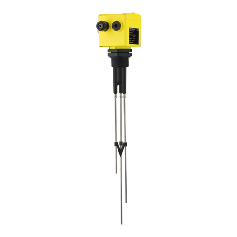
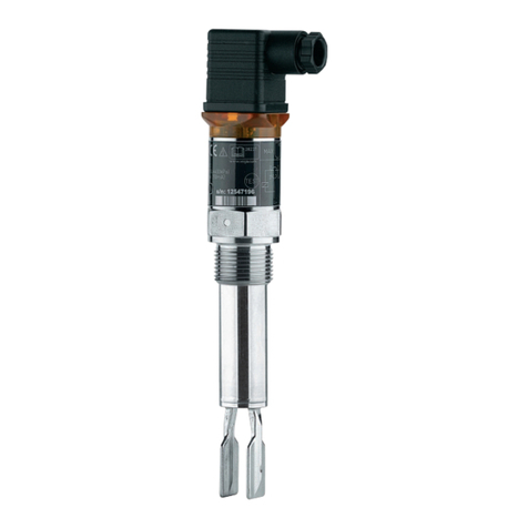
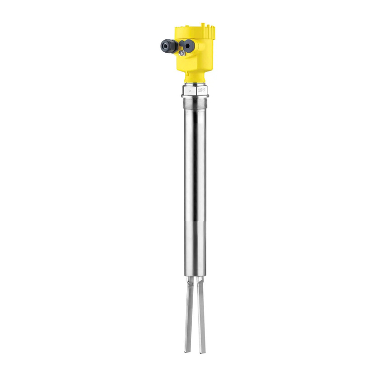
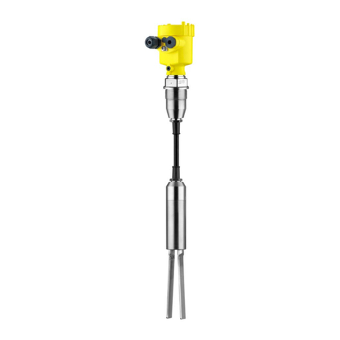
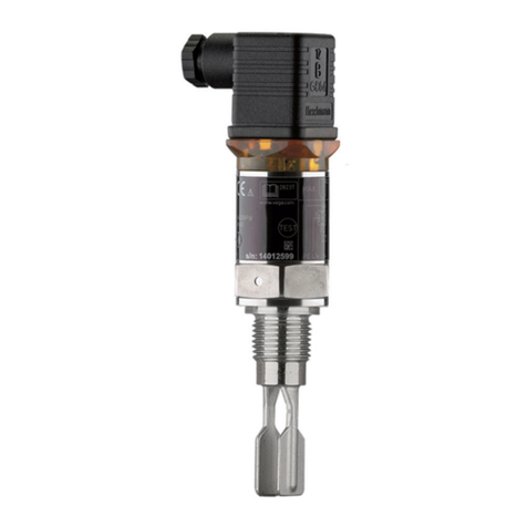
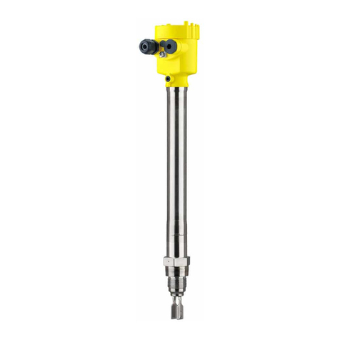
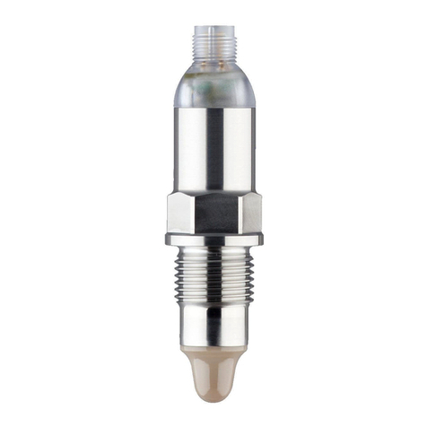
Vega VEGASWING 66 User guide

Safety Manual
VEGASWING 66
Two-wire (8/16 mA)
With SIL qualication
Document ID: 45309

2
Contents
VEGASWING 66 • Two-wire (8/16 mA)
45309-EN-130722
Contents
1 Document language
2 Scope
2.1 Instrument version............................................................................................................ 4
2.2 Area of application ........................................................................................................... 4
2.3 SIL conformity .................................................................................................................. 4
3 Planning
3.1 Safety function ................................................................................................................. 5
3.2 Safe state......................................................................................................................... 5
3.3 Prerequisites for operation ............................................................................................... 5
4 Safety-related characteristics
4.1 Parameter according to IEC 61508................................................................................... 7
4.2 Figures according to ISO 13849-1.................................................................................... 7
4.3 Supplementary information .............................................................................................. 7
5 Setup
5.1 General information.......................................................................................................... 9
5.2 Instrument parameter adjustment..................................................................................... 9
6 Diagnostics and service
6.1 Behaviour in case of failure ............................................................................................ 10
6.2 Repair ............................................................................................................................ 10
7 Proof test
7.1 General information........................................................................................................ 11
7.2 Test1-withoutllingordismountingthesensor ............................................................ 11
7.3 Test2-withllingordismountingofthesensor ............................................................. 12
8 Appendix A - Test report
9 AppendixB-Te r m denitions
10 Supplement C - SIL conformity
Editing status: 2013-07-22

3
1 Document language
VEGASWING 66 • Two-wire (8/16 mA)
45309-EN-130722
1 Document language
DE Das vorliegende Safety Manual für Funktionale Sicherheit ist verfügbar in den Sprachen
Deutsch, Englisch, Französisch und Russisch.
EN The current Safety Manual for Functional Safety is available in German, English, French and
Russian language.
FR Le présent Safety Manual de sécurité fonctionnelle est disponible dans les langues suivantes:
allemand, anglais, français et russe.
RU ДанноеруководствопофункциональнойбезопасностиSafety Manualимеетсяна
немецком,английском,французскомирусскомязыках.

4
2 Scope
VEGASWING 66 • Two-wire (8/16 mA)
45309-EN-130722
2 Scope
2.1 Instrument version
This safety manual applies to point level sensors
VEGASWING 66 - Two-wire (8/16 mA)withSILqualication
Electronics module:
•SG60HT-L
Valid versions:
•from HW Ver 1.0.0
•from SW Ver 1.1.0
The version "remote housing" is excluded!
Permissible version of VEGATOR 636:
•from HW Ver 1.0.1
2.2 Area of application
The instrument can be used for level detection of liquids in a safety-
related system according to IEC 61508 in the modes low demand
mode or high demand mode:
•Up to SIL2 in a single-channel architecture
•Up to SIL3 in a multiple-channel architecture
The following interface should be used to output the measured value:
•Two-wire current output 8/16 mA
2.3 SIL conformity
TheSILconformitywasindependentlyjudgedandcertiedbythe
TÜV Rheinland according to IEC 61508:2010 (Ed.2).1)
Thecerticateisvalidfortheentireservicelifeofallinstrumentsthat
weresoldbeforethecerticateexpired!
Operation with
VEGATOR 636 signal
conditioning instrument
1) Verication documents see appendix

5
3 Planning
VEGASWING 66 • Two-wire (8/16 mA)
45309-EN-130722
3 Planning
3.1 Safety function
To monitor a limit level, the sensor detects via the conditions "Vibrat-
ing element uncovered" or "Vibrating element covered" a limiting
valuedenedbythemountinglocation.
The determined status is signalled at the output with "Current = 8 mA"
or "Current = 16 mA".
3.2 Safe state
The safe status of the output signal is independent of the mode
adjusted on the sensor.
Mode Overowprotection
(mode max.)
Dry run protection
(mode min.)
Vibrating element covered uncovered
Output current 16 mA ±1.5 mA 16 mA ±1.5 mA
When operating with a signal conditioning instrument VEGATOR 636
or VEGATOR series 100 max. mode must be adjusted on the sen-
sor. The selection of the mode is carried out on the signal condition-
ing instrument.
Mode Overowprotection
(mode max.)
Dry run protection
(mode min.)
Vibrating element covered uncovered
Output current 16 mA ±1.5 mA 8mA ±1.5 mA
The safe status of the output signal is independent of the mode evalu-
ated by an SPLC.
Mode Overowprotection Dry run protection
Vibrating element covered uncovered
Output current when mode
on the sensor is set to
"max."
16 mA ±1.5 mA 8mA ±1.5 mA
Output current when mode
on the sensor is set to
"min."
8mA ±1.5 mA 16 mA ±1.5 mA
Possible fault currents:
•≤3.6mA("faillow")
•> 21 mA ("fail high")
3.3 Prerequisites for operation
•The measuring system should be used appropriately taking pres-
sure, temperature, density and chemical properties of the medium
intoaccount.Theapplication-speciclimitsmustbemaintained.
Safety function
Safe condition when
selecting the mode on the
sensor
Safe condition when
operating with a signal
conditioning instrument
Safe condition when op-
erating with an SPLC
Output signals in case of
malfunction
Instructions and restric-
tions

6
3 Planning
VEGASWING 66 • Two-wire (8/16 mA)
45309-EN-130722
•Thespecicationsaccordingtotheoperatinginstructionsmanual,
particularly the current load of the output circuits, must be kept
withinthespeciedlimits
•The instructions in chapter "Safety-related characteristics", para-
graph "Supplementary information" must be noted
•All parts of the measuring chain must correspond to the planned
"Safety Integrity Level (SIL)"

7
4 Safety-related characteristics
VEGASWING 66 • Two-wire (8/16 mA)
45309-EN-130722
4 Safety-related characteristics
4.1 Parameter according to IEC 61508
Parameter Value
Safety Integrity Level SIL2 in single-channel architecture
SIL3 in multiple channel architecture2)
Hardware error tolerance HFT = 0
Instrument type Type B
Mode Low demand mode, High demand mode
SFF > 90 %
MTTR 8 h
MTBF = MTTF + MTTR3) 1.25 x10⁶ h (143 years)
Diagnosis test interval4) < 120 s
Fault reaction time5) < 2 s
Failure rates
λSλDD λDU λHλLλAD λAU
0 FIT 307 FIT 29 FIT 3 FIT 81 FIT 11 FIT 8 FIT
PFDAVG 0.025 x10⁻² (T1 = 1 year)
PFDAVG 0.036 x10⁻² (T1 = 2 years)
PFDAVG 0.071 x10⁻² (T1 = 5 years)
PFH 0.029 x10⁻⁶ 1/h
4.2 Figures according to ISO 13849-1
Derived from the safety-related characteristics, there are the following
guresaccordingtoISO13849-1(machinesafety):6)
Parameter Value
MTTFd 265 years
DC 93 %
Performance Level 2.95 x10⁻⁸ 1/h (corresponds to "e")
4.3 Supplementary information
The failure rates of the instrument were determined by an FMEDA
according to IEC 61508. Basis for the calculations are the component
failure rates according to SN 29500.
Determination of the
failure rates
2) Homogeneous redundancy possible
3) Including errors outside the safety function
4) Time during which all internal diagnoses are carried out at least once
5) Time between the occurrence of the event and the output of a fault signal.
6) ISO 13849-1 was not part of the certication of the instrument.

8
4 Safety-related characteristics
VEGASWING 66 • Two-wire (8/16 mA)
45309-EN-130722
Allguresrefertoanaverageambienttemperatureof40°C(104°F)
during the operating time. For higher temperatures, the values should
be corrected:
•Continuousapplicationtemperature>50°C(122°F)byfactor1.3
•Continuousapplicationtemperature>60°C(140°F)byfactor2.5
Similarfactorsapplyiffrequenttemperatureuctationsareexpected.
•The failure rates are constant. Take note of the useful life of the
components according to IEC 61508-2.
•Multiple errors are not taken into account
•Wear on mechanical parts is not taken into account
•Failure rates of external power supplies are not taken into account
•The environmental conditions correspond to an average industrial
environment
The values for PFDAVGspeciedabovewerecalculatedasfollowsfora
1oo1 architecture:
PFDAVG= +λDD x MTTR +
PTC × λ
DU
× T1
2
(1 – PTC) ×
λ
DU
× LT
2
•T1 (Proof Test Interval)
•MTTR = 8 h
•PTC = 90 %
•LT = 10 years
A connected control and processing unit must have the following
properties:
•The output circuit of the transmitter is judged according to the
quiescent current principle
•"fail low" and "fail high" signals are interpreted as a failure, which
triggers a fault message
If this is not the case, the respective percentages of the failure rates
must be assigned to the dangerous failures and the values stated in
chapter Safety-related characteristics“ redetermined!
In multiple channel systems for SIL3 applications, this measuring sys-
temcanalsobeusedinahomogeneouslyredundantconguration.
The safety-related characteristics must be calculated especially for
the selected structure of the measuring chain using the stated failure
rates. In doing this, a suitable Common Cause Factor must be consid-
ered (see IEC 61508-6, appendix D).
Assumptions of the
FMEDA
Calculation of PFDAVG
Boundary conditions re-
latingtotheconguration
of the processing unit
Multiple channel archi-
tecture

9
5 Setup
VEGASWING 66 • Two-wire (8/16 mA)
45309-EN-130722
5 Setup
5.1 General information
Take note of the mounting and installation instructions of the operating
instructions manual.
5.2 Instrument parameter adjustment
The following adjustment elements are used to parameterize the
safety function:
•Slide switch for changeover of the mode (min./max.)
•Slide switch for changeover of the sensitivity
The function of the adjustment elements is described in the operating
instructions manual.
When operating with a signal conditioning instrument VEGATOR 636
or VEGATOR series 100 max. mode must be adjusted on the sen-
sor. The selection of the mode is carried out on the signal condition-
ing instrument.
During parameter adjustment, the safety function must be considered
as unreliable!
If necessary, you must take other measures to maintain the safety
function.
The sensor must be protected against inadvertent or unauthorized
modication!
Mounting and installation
Adjustment elements
Operation with a signal
conditioning instrument
Instructions

10
6 Diagnostics and service
VEGASWING 66 • Two-wire (8/16 mA)
45309-EN-130722
6 Diagnostics and service
6.1 Behaviour in case of failure
If a malfunction is detected, the respective output signals change to
safe condition (see section "Safe condition").
This condition is maintained for at least 1 second. If an error is no
longer detected, the safety function is performed correctly again.
Thediagnosisintervalisspeciedinchapter"Safety-related charac-
teristics".
6.2 Repair
If faults are detected, the entire measuring system must be shut down
and the process held in a safe state by other measures.
The manufacturer must be informed of the occurrence of a danger-
ous, undetected error (incl. fault description).
The procedure is described in the operating instructions manual. Note
the instructions for parameter adjustment and setup.
Internal diagnosis
Reaction when malfunc-
tions occur
Electronics exchange

11
7 Proof test
VEGASWING 66 • Two-wire (8/16 mA)
45309-EN-130722
7 Proof test
7.1 General information
To identify possible undetected, dangerous failures, the safety func-
tion must be checked in adaquate intervals by a proof test. It is the
user's responsibility to choose the type of testing. The time intervals
are subject to the PFDAVG in chapter "Safety-related characteristics".
For documentation of these tests, the test protocol in the appendix
can be used.
If one of the tests proves negative, the entire measuring system must
be switched out of service and the process held in a safe state by
means of other measures.
In a multiple channel architecture this applies separately to each
channel.
•Determine safety function (mode, switching points)
•If necessary, remove the instruments from the safety chain and
maintain the safety function by other means
Warning:
During the function test, the safety function must be treated as unsafe.
Itmustbenotedthatthefunctiontestinuencesdownstreamcon-
nected devices.
If necessary, you must take other measures to maintain the safety
function.
Afterthefunctiontest,thestatusspeciedforthesafetyfunctionmust
be restored.
7.2 Test1-withoutllingordismountingthe
sensor
•Instrument in installed condition
•Output signal corresponds to the level (covered or uncovered
vibrating element)
1. Carry out a restart (push test key on the sensor or on the signal
conditioning instrument)
2. Push the min./max. switch
to1:Outputofadenedstartingcurrentinthreesteps:
Fault message - Empty signal - Full signal (see operating instruc-
tions). Afterwards, the output signal corresponds to the level.
to 2: Output signal changes status
Remaining dangerous, undetected failures: 12 FIT (PTC = 61 %)
Objective
Preparation
Unsafe device
status
Conditions
Procedure
Expected result
Coverage of the test

12
7 Proof test
VEGASWING 66 • Two-wire (8/16 mA)
45309-EN-130722
7.3 Test2-withllingordismountingofthe
sensor
•Alternative 1: the instrument remains mounted; the condition
"Vibrating element uncovered"/"Vibrating element covered" can be
changedbyllingoremptyingtotheswitchingpoint.
•Alternative 2: the instrument is dismounted; the condition "Vibrat-
ing element uncovered"/"Vibrating element covered" can be
changed by dipping the instrument into the original medium
•Output signal corresponds to the level (covered or uncovered
vibrating element)
1. Carry out a restart (push test key on the sensor or on the signal
conditioning instrument)
2. Push the min./max. switch
3. Filling or emptying up to the switching point or immersion into the
original medium
to1:Outputofadenedstartingcurrentinthreesteps:
Fault message - Empty signal - Full signal (see operating instruc-
tions). Afterwards, the output signal corresponds to the level.
to 2: Output signal changes status
to3:Outputsignalcorrespondstothemodiedlevel
Remaining dangerous, undetected failures: 2 FIT (PTC = 95 %)
Conditions
Procedure
Expected result
Coverage of the test

13
8 Appendix A - Test report
VEGASWING 66 • Two-wire (8/16 mA)
45309-EN-130722
8 Appendix A - Test report
Identication
Company/Tester
Plant/Instrument TAG
Meas. loop TAG
Instrument type/Order code
Instrument serial number
Date, setup
Date, last function test
Test reason/Test scope
Setupwithout"llingordismountingthesensor"
Setupwith"llingordismountingthesensor"
Prooftestwithout"llingordismountingthesensor"
Prooftestwith"llingordismountingthesensor"
Mode
Overowprotection
Dry run protection
Sensitivity
≥0.7g/cm³(0.025lbs/in³)
≥0.5g/cm³(0.018lbs/in³)
Test result (if necessary)
Test step Level Expected measured
value
Real value Test result
Conrmation
Date: Signature:

14
9AppendixB-Termdenitions
VEGASWING 66 • Two-wire (8/16 mA)
45309-EN-130722
9 AppendixB-Te r m denitions
SIL Safety Integrity Level
HFT Hardware Fault Tolerance
SFF Safe Failure Fraction
PFDAVG Average Probability of dangerous Failure on Demand
PFH Average frequency of a dangerous failure per hour (Ed.2)
FMEDA FailureMode,EectsandDiagnosticsAnalysis
FIT Failure In Time (1 FIT = 1 failure/109h)
λSD Rate for safe detected failure
λSU Rate for safe undetected failure
λSλS=λSD+λSU
λDD Rate for dangerous detected failure
λDU Rate for dangerous undetected failure
λHRate for failure, who causes a high output current (> 21 mA)
λLRateforfailure,whocausesalowoutputcurrent(≤3.6mA)
λAD Rate for diagnostic failure (detected)
λAU Rate for diagnostic failure (undetected)
DC Diagnostic Coverage
PTC Proof Test Coverage
T1 Proof Test Interval
LT Life Time
MTBF Mean Time Between Failure
MTTF Mean Time To Failure
MTTR Mean Time To Restoration (Ed.2)
MTTFdMean Time To dangerous Failure (ISO 13849-1)
PL Performance Level (ISO 13849-1)
Abbreviations

15
10 Supplement C - SIL conformity
VEGASWING 66 • Two-wire (8/16 mA)
45309-EN-130722
10 Supplement C - SIL conformity

Printing date:
VEGA Grieshaber KG
Am Hohenstein 113
77761 Schiltach
Germany
45309-EN-130722
All statements concerning scope of delivery, application, practical use and operat-
ing conditions of the sensors and processing systems correspond to the information
available at the time of printing.
Subject to change without prior notice
© VEGA Grieshaber KG, Schiltach/Germany 2013
Phone +49 7836 50-0
Fax +49 7836 50-201
E-mail: [email protected]
www.vega.com
Other manuals for VEGASWING 66
6
Table of contents
Other Vega Switch manuals

Vega
Vega VEGAWAVE 61 User manual

Vega
Vega VEGASWING 53 User manual
Vega
Vega VEGAWAVE 63 User manual

Vega
Vega VEGASWING 51 User manual

Vega
Vega VEGACAP 64 User manual

Vega
Vega VEGAWAVE S 61 Instruction Manual

Vega
Vega VEGATOR 121 User manual

Vega
Vega VEGACAP 65 User manual

Vega
Vega VEGASWING 63 User manual

Vega
Vega VEGASWING 66 User manual

Vega
Vega VEGAWAVE 62 User manual

Vega
Vega VEGASWING 61 User manual

Vega
Vega VEGAPOINT 21 User manual

Vega
Vega VEGASWING 51 User manual

Vega
Vega VEGAVIB 63 User manual
Vega
Vega VEGAPOINT 24 User manual

Vega
Vega VEGAWAVE S 61 User manual

Vega
Vega VEGASWING 51 User manual

Vega
Vega VEGASWING 63 User manual
Vega
Vega VEGAKON 66 User manual