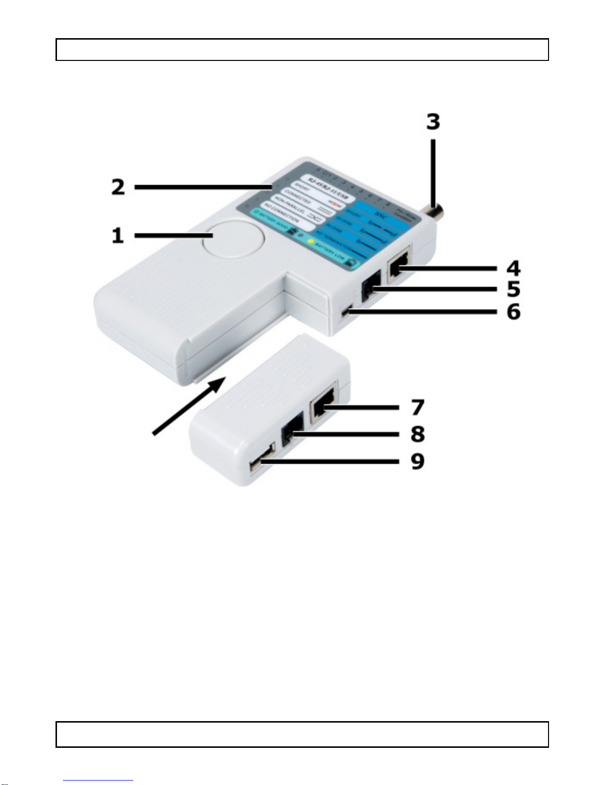
Velleman VTLAN7 User manual

VTLAN7
NETWORK CABLE (LAN) TESTER
LA N TE STER
TE STEUR LA N
COMPROBADOR DE CABLE LAN
LAN-TES TE R
TESTADORDE CABOSLAN
TE STER SIECI LA N
for - voor - pour - para - für – do:
USER MANUAL 3
GEBRUIKERSHANDLEIDING 10
MODE D'EMPLOI 17
MANUAL DEL USUARIO 24
BEDIENUNGSANLEITUNG 31
MANUAL DO UTILIZADOR 38
INSTRUKCJA OBSŁUGI 45
4P4C (RJ10)
6P2C (RJ11)
6P6C (RJ12)
8P8C (RJ45)
BNC
USB A/Mini-B

VTLAN7
V. 01 – 30/10/2013 2 ©Velleman nv

VTLAN7
V. 01 – 30/10/2013 3 ©Velleman nv
USER MANUAL
1. Introduction
To all residents of the European Union
Important environmental information about this product
This symbol on the device or the package indicates that
disposal of the device after its lifecycle could harm the
environment. Do not dispose of the unit (or batteries) as
unsorted municipal waste; it should be taken to a
specialized company for recycling. This device should be
returned to your distributor or to a local recycling service. Respect
the local environmental rules.
If in doubt, contact your local waste disposal authorities.
Thank you for choosing Velleman! Please read the manual thoroughly
before bringing this device into service. If the device was damaged in
transit, don't install or use it and contact your dealer.
2. Safety Instructions
Never use the testeron live wires; this will damage the
tester.
There are no user-serviceable parts inside the device.
Refer to an authorized dealer for service and/or spare
parts.
Refer to the Velleman® Service and Quality Warranty on the last
pages of this manual.
•Indoor use only. Keep this device away from rain, moisture,
splashing and dripping liquids. Never put objects filled with liquids
on topof or close to the device.
•Keep this device away from dust and extreme temperatures.
•Protect this device from shocks and abuse. Avoid brute force when
operating the device.
•Familiarise yourself with the functions of the device before actually
using it.
•All modifications of the device are forbidden forsafety reasons.
Damage caused by user modifications to the device is not covered
by the warranty.

VTLAN7
V. 01 – 30/10/2013 4 ©Velleman nv
•
Onlyuse the device for its intended purpose. Using the device in
an unauthorised way will void the warranty.
•Damage caused by disregard of certain guidelines in this manual
is not covered by the warranty and the dealer will not accept
responsibility forany ensuing defects orproblems.
•Keep this manual for future reference.
3. Features
•LED indication
•advanced design for easy te sting
•ability to test cables from a distance and in places that are not
easily accessible
•automatically runs all testsand checks for continuity, open,
shorted and crossed wire pairs.
4. Overview
Refer to the illustrations on page 2 of this manual.
Master
Remote
1 Test button 7 RJ45 s o cke t
2
Display
9
RJ11 s o cke t
3
BNC s o cke t
9
USB socket (A)
4
R J45 s o cke t
5 R J11 s o cke t
6 USB socket (Mini-B)
5. Operation
Supported cables
•The device te sts common LAN and computer cables.
•It tests installed cables or patch cords with USB-A-to-Mini-B, BNC,
RJ45 (8P8C), RJ12 (6P6C),RJ11 (6P2C), RJ10 (4P4C) connectors.
•It is intended to test cables with straight through connections, not
cables with reversed or transposed connections like some LAN
crossover cables or reverse wired telephone cables.

VTLAN7
V. 01 – 30/10/2013 5 ©Velleman nv
Test conditions
To avoid test errors:
•Do not test near strong magnetic fields (magnets, loudspeakers,
transformers, motors, coils, relays, contactors,electromagnets,
etc.).
•Do not test near strong electrostatic fields (high voltage power
lines, televisions, computer monitors, etc.).
•Do not test near strong RF fields (radio or television transmitters,
walkie-talkies, cellular phones etc.).
5.2 Test ing an RJ45 cable
Never use the
testeron live wires; this may cause shocks
or damage the meter.
Notes
•Only one cable can be tested at a time. For example, a coaxial
cable and an RJ45 cable cannot be tested simultaneously.
•The tester is intended to test complete cables. It may no find
faults in cables that are intentionally incomplete. For example, the
standard EIA/TIA 568 RJ45 terminated Ethernet cable is expected
to contain 8 conductors. If only 4 conductors are used between
the RJ45 connectors, the device may not properly identify the
faults.
To test a cable:
1. Insert one end of the cable under test into the appropriate
s o ck e t in the master.
2. Insert the other end of the cable into the corresponding socket
in the remote.
3. Press and release the Test button [1].
The power LED will light up forat least5 seconds, indicating the
device is testing the cable. If the power LED does not light,
replace the battery.
5.3 Test result
The tables below describe the test results (LEDs that light up and
number of beeps) for various error types.

VTLAN7
V. 01 – 30/10/2013 6 ©Velleman nv
Good connection
Visible LEDsBeepsNote
•CONNECTED
•All numbered LEDs 2: low-high The numbered LEDs do not
indicate that a good
connection exists, only
that a connection exists.
Open fault
Visible LEDs BeepsNote
•
CONNECTED
•Correct connections
2: low-high
The LEDs of the
interrupted connections do
not light up.
Short circuit
Visible LEDs
Beeps
Note
•
SHORT
•Faulty connections
3 beeps
•
The cable has a short
circuit.
•The number LED
indicates the location of
the short.

VTLAN7
V. 01 – 30/10/2013 7 ©Velleman nv
Crossed connections
Visible LEDs BeepsNote
•NON-PARALLEL
•All numbered LEDS 2 beeps •Cables are crossed.
•The numbered LEDs
indicate connections but
do not indicate the
location of the cross.
No connection
Visible LEDs
Beeps
Note
NO CONNECTION
1 beep
•
There is no cable
between the remote
and the main unit.
•The cable has no intact
conductors.
5.4 Test ing an RJ 11 cable
Testing RJ11 cables is similar to RJ45 cables.
An RJ11 cable can have 2, 4, or 6 connections.
Depending on the number of connections, the LEDs will light as
follows (provided the cable is OK):
•2 connections: LED 3 - 4
•4 connections: LED 2 - 3 - 4 - 5
•6 connections: LED 1 - 2 - 3 - 4 - 5 - 6.
5.5 Test ing a coaxial cable (BNC)
The device can test25 Ω , 50 Ω, a nd 75 Ω cables.
1. Connect one end of the cable to the BNC connector.
2. Attach a suitable terminator to the other end of the cable.
3. Press the Test button.
The LED corresponding to the error lights up.
Results
•SHORT: short circuit
•CONNECTED: cable is OK.
•NON-PARALLEL: crossed connection.
•NO CONNECTION: cable has no terminator or is defective.

VTLAN7
V. 01 – 30/10/2013 8 ©Velleman nv
5.6 Testing a USB cable
1. Connect the Mini-B end to the socket on the master and the
USB A end to the remote.
2. Press the Test button.
The LED next to CONNECTED and the numbered LEDs 1 to 4
light up if the cable is OK.
6. Battery
Warning
•Do not puncture batteries or throw them in fire as they
may explode.
•Do not attempt to recharge non-rechargeable batteries
(alkaline).
•
Dispose of batteries in accordance with local regulations.
Keep batteries away from children.
•
Remove the battery from the device if it will not be use
d
for a long time. Old batteries can begin to leak and
damage the device.
Notes
•The device has a battery lowindicator. Replace the battery as
soon as the indicator lights up. A low battery power may produce
false readings.
•To replace the battery:
1. Slide open the battery coverat the back and replace with a
correct batte ry (see Technical Specifications). Respect the
polarity.
2. Close the battery cover.
7. Cleaning and Maintenance
•The tester is a precision test instrumentand, when usedas
described in this manual, should not require maintenance.
•Calibration is not required.
•To clean the outside of the tester, use a cloth dampened with a
mild detergentsolution. Do notuse any abrasive cleansers or
chemical solvents that may damage the case of the tester.

VTLAN7
V. 01 – 30/10/2013 9 ©Velleman nv
8. Tec hnical Specifications
5-in-1 cable tester USB, RJ45, 10BASE-T, token ring,
RJ11/12 cables, BNC cables
power supply 9 V battery 6LR61C (not incl.)
max. cable length for testing 200 m
Use this device with original accessories only. Velleman nv
cannot be held responsible in the event of damage or injury
result ing from (incorrect) use of this device. For more info
concerning this product and the latest version of this manual,
please visit our website www.velleman.eu. The information in
this manual is subject to change without prior notice.
© COPYRIGHT NOTICE
The copyright to this manual is owned by Velleman nv. All
worldwide rights reserved. No part of this manual may be copied,
reproduced, translated or reduced to any electronic medium or
otherwise without the prior written consent of the copyright holder.

VTLAN7
V. 01 – 30/10/2013 10 ©Velleman nv
GEBRUIKERSHANDLEIDING
1. Inleiding
Aan alle ingezetenen van de Europese Unie
Belangrijke milieu-informatie betreffende dit product
Dit symbool op het toestel of de verpakking geeft aan dat,
als het na zijn levenscyclus wordt weggeworpen, dit toestel
schade kan toebrengen aan het milieu. Gooi dit toestel (en
eventuele batterijen) nietbij hetgewone huishoudelijke
afval; hetmoetbijeen gespecialiseerd bedrijf
terechtkomen voor recyclage. Umoetdit toestel naar uwverdeler of
naareen lokaal recyclagepunt brengen. Respecteer de plaatselijke
milieuwetgeving.
Hebt u vragen, contacteer dan de plaatselijke autoriteiten
betreffende de verwijdering.
Dank u voor uw aankoop! Lees deze handleiding grondig voor u het
toestel in gebruik neemt. Werd het toestel beschadigd tijdens het
transport, installeer het dan niet en raadpleeg uw dealer.
2. Veiligheidsinstructies
Gebruik dit toestel nooit op kabels die onder spanning
staan; dit zal de testerbeschadigen.
Er zijn geen door de gebruiker vervangbare onderdelen in
dit
toestel. Vooronderhoud en/of reserveonderdelen,
contacteeruwdealer.
Raadpleeg de Velleman® service- en kwaliteitsgarantie
achteraan deze handleiding.
•Gebruik het toestel enkel binnenshuis. Bescherm hettoestel
tegen regen, vochtigheid en opspattende vloeistoffen. Plaats geen
objecten gevuld met vloeistof op of naast het toestel.
•Bescherm dit toestel tegen stof enextreme temperaturen.
•Bescherm tegen schokken. Vermijd brute kracht tijdens de
bediening.
•Leer eerstde functies van het toestel kennen voor u het gaat
gebruiken.

VTLAN7
V. 01 – 30/10/2013 11 ©Velleman nv
•Om veiligheidsredenen mag u geen wijzigingen aanbrengen.
Schade door wijzigingen die de gebruiker heeft aangebracht aan
het toestel valtniet onderde garantie.
•Gebruik het toestel enkel waarvoor het gemaakt is. De garantie
vervalt automatisch bij ongeoorloofd gebruik.
•
De garantie geldt niet voorschade door hetnegeren van bepaalde
richtlijnen in deze handleiding en uwdealer zal de
verantwoordelijkheid afwijzen voor defecten of problemen die hier
rechtstreeks verband mee houden.
•Bewaar deze handleiding voor verdere raadpleging.
3. Eigenschappen
•LED-indicatie
•geavanceerd ontwerp maakthet testeneenvoudig
•u kunt kabels testen van op afstand en opmoeilijk bereikbare
plaatsen
•voert automatisch alle testen uit voor continuïteit, open,
kortgesloten en gekruiste bedrading.
4. Omschrijving
Raadpleeg de afbeeldingen op pagina 2 van deze handleiding.
Master
Remote
1 Testknop 7 RJ45-aansluiting
2 Display 9 RJ11-aansluiting
3 BNC-aansluiting 9 USB-aansluiting (A)
4 RJ45-aansluiting
5
RJ11-aansluiting
6 USB-aansluiting (mini-B)
5. Gebruik
Ondersteunde kabels
•Het toestel test de gangbare netwerk- en computerkabels.
•Het testreeds geïnstalleerde kabels of patchkabelsmetUSB-A-
naar-Mini-B, BNC, RJ45 (8P8C), RJ12 (6P6C), RJ11 (6P2C), RJ10
(4P4C)-connectoren.

VTLAN7
V. 01 – 30/10/2013 12 ©Velleman nv
•Het toestel test kabelsmetrechte aansluitingen, geen
omgekeerde of verwisselde aansluitingen (bijv. bepaalde
crossover-
netwerkkabels of omgekeerde bedrade telefoonkabels).
Testvoorwaarden
Om testfouten te vermijden:
•Niet gebruiken in de nabijheid van sterkemagnetische velden
(magneten, luidsprekers, transformatoren, motoren, spoelen,
relais, contactoren, elektromagneten, enz.).
•
Niet gebruiken in de nabijheid van sterke elektrostatische velden
(hoogspanningskabels, televisietoestellen, computerschermen,
enz.).
•Niet gebruiken in de nabijheid van sterke RF-velden (radio- of
televisiezenders, walkietalkies, mobiele telefoons, enz.).
5.2 Een RJ45-kabel testen
Gebruik dit toestel nooit op kabels die onder spanning
staan; dit kan elektrische schokken veroorzaken of de
meterbeschadigen.
Opmerkingen
•
U kunt slechts één kabel perkeer testen. U kuntbijvoorbeeld een
coaxkabel eneen RJ4-kabel niet gelijktijdig testen.
•Het toestel test volledige kabels. Het toestel detecteert geen
fouten inkabels die metopzetonvolledig gemaakt zijn.
Bijvoorbeeld, de standaard EIA/TIA-68 RJ45-ethernetkabel met
terminator is normaal voorzien van 8 geleiders. Indien er slechts 4
geleiders tussen de RJ45-connectoren gebruikt worden, dankan
het toestel de fouten nietcorrect identificeren.
Een kabel testen:
1. Sluit één uiteinde van de testkabel aan op het master-toestel.
2. Sluit het andere uiteinde van dekabel aan op het remote-
toeste l.
3. Druk kort op de testknop [1].
De voedingsled licht 5 seconden op, om aan te geven dathet
toestel dekabel aan het testen is. Vervang de batterij als de
voedingsled niet oplicht.

VTLAN7
V. 01 – 30/10/2013 13 ©Velleman nv
5.3 Testresultaat
Raadpleeg de onderstaande tabellen vooreen beschrijving van de
testresultaten (leds die oplichten en aantal signaaltonen) voor
verschillende fouttypes.
Goede verbinding
Zichtbare leds
Signaaltonen
Opmerking
•CONNECTED
•
Alle genummerde leds
2: laag-hoog De genummerde leds
geven niet aan dater een
goede verbinding is, maar
alleen dat er een
verbinding is.
Onderbreking
Zichtbare leds Signaaltonen Opmerking
•CONNECTED
•Correcte verbindingen 2: laag-hoog De leds van de
onderbroken verbindingen
lichten niet op.

VTLAN7
V. 01 – 30/10/2013 14 ©Velleman nv
Kortsluiting
Zichtbare leds Signaaltonen Opmerking
•SHORT
•Foute verbindingen 3 signaaltonen •Er is een kortsluiting in
de kabel.
•De genummerde led
geeftde plaats van de
kortsluiting weer.
Gekruiste verbindingen
Zichtbare leds
Signaaltonen
Opmerking
•
NON-PARALLEL
•
Alle genummerde leds
2 signaaltonen
•
De kabels zijn gekruist.
•De genummerde leds
geven de verbindingen
aan maar niet de plaats
waar de kabels gekruist
zijn.
Geen verbinding
Zichtbare leds Signaaltonen Opmerking
NO CONNECTION 1 signaaltoon •Er is geen verbinding
tussen het remote- en
het master-toestel.
•De kabel heeft geen
onbeschadigde
geleiders.
5.4 Een RJ11-kabel testen
Het testen van RJ11- en RJ45-kabels is gelijkaardig.
Een RJ11-kabel kan 2, 4 of 6 aansluitingen hebben.
Afhankelijk van het aantal aansluitingen, lichten de leds als volgt op
(op voorwaarde dat de kabel goed is):
•2 aansluitingen: led 3 - 4
•4 aansluitingen: led 2 - 3 - 4 - 5
•6 aansluitingen: led 1 - 2 - 3 - 4 - 5 - 6.
5.5 Een coaxkabel testen (BNC)
Het toestel kan 25 Ω , 50 Ω , e n 75 Ω-kabels testen.
1. Sluit één uiteinde van de kabel aan op de BNC-aansluiting.

VTLAN7
V. 01 – 30/10/2013 15 ©Velleman nv
2. Plaats een geschikte terminatorop hetandere uiteinde van de
kabel.
3. Druk op de testknop.
De led die met de fout overeenkomt, licht op.
Resultaten
•SHORT: kortsluiting
•CONNECTED: kabel is OK.
•NON-PARALLEL: gekruiste verbinding.
•NO CONNECTION: kabel heeft geen terminator of is defect.
5.6 Een USB-kabel testen
1. Sluit het Mini-B-uiteinde van de kabelaan op hetmaster-toestel
en het USA-A-uiteinde van de kabel op het remote-toestel.
2. Druk op de testknop.
Wanneer de kabel goed is, licht de led naast CONNECTED op
6. Batterij
Waarschuwing
•U mag batterijen nooit
doorboren of in het vuur gooien
(explosiegevaar).
•Herlaad geenalkalinebatterijen.
•Gooi batterijen weg volgens de plaatselijke
milieuwetgeving. Houd batterijen uithet bereik van
kinderen.
•
Verwijder de batterij als het toestel gedurende een
langere tijd niet gebruikt wordt. Oude batterijen kunnen
lekken en het toestel beschadigen.
Opmerkingen
•Het toestel is uitgerustmet een legebatterij-indicator. Vervang de
batterij van zodra de indicator oplicht. Een lage batterijspanning
kan leiden tot onjuiste resultaten.
•De batterij vervangen:
1.
Schuif het batterijdeksel aan de achterkant van het toestel open
en plaats een nieuwe batterij (zie Technische specificaties).
Respecteerde polariteit.
2. Sluit het batterijdeksel.

VTLAN7
V. 01 – 30/10/2013 16 ©Velleman nv
7. Reiniging en onderhoud
•De tester is een precisie-testinstrument en, heeft bij gebruik zoals
beschreven in deze handleiding, geen onderhoud nodig.
•Kalibratie is niet vereist.
•Gebruik een vochtige doek meteen milde zeepoplossing, om de
behuizing van de tester te reinigen. Gebruik geen schurende
schoonmaakm iddelen of chemische oplosmiddelen die de
behuizing van de tester kunnen beschadigen.
8. Technische specificaties
5-in-1 kabeltester
USB, RJ45, 10BASE-T, Token Ring,
RJ11/12-kabels, BNC kabels
voeding 9 V-
batterij 6LR61C (niet meegelev.)
max. lengte van de testkabel
200 m
Gebruik dit toestel enkel met originele accessoires. Velleman
nv is niet aansprakelijk voor schade of kwetsuren bij
(verkeerd) gebruik van dit toestel. Voor meer informatie over
dit product en de laatste versie van deze handleiding, zie
www.velleman.eu. De informatie in deze handleiding kan te
allen tijde worden gewijzigd zonder voorafgaande
kennisgeving.
© AUTEURSRECHT
Velleman nv heeft het auteursrecht voor deze handleiding.
Alle wereldwijde rechten voorbehouden. Het is niet toegestaan
om deze handleiding of gedeelten ervan over te nemen, te kopiëren,
te vertalen, te bewerken en op te slaan opeen elektronisch medium
zonder voorafgaande schriftelijke toestemming van de
rechthebbende.

VTLAN7
V. 01 – 30/10/2013 17 ©Velleman nv
MODE D'EMPLOI
1. Introduction
Aux résidents de l'Union européenne
Informations environnementales importantes concernant ce
produit Ce symbole sur l'appareil ou l'emballage indique que
l'élimination d'un appareil en fin de vie peut polluer
l'environnement. Ne pas jeterun appareilélectrique ou
électronique (etdes piles éventuelles) parmi les déchets
municipaux non sujets au tri sélectif; une déchèterie
traitera l'appareil en question. Renvoyer cet appareil à votre
fournisseur ou à un service de recyclage lo ca l. I l co nvie n t de
respecterla réglementation locale relative à la protection de
l'environnement.
En cas de questions, contacter les autorités locales pour
élim ination.
Nous vous remercions de votre achat ! Lire le présent mode d'emploi
attentivement avant la mise en service de l'appareil. Si l'appareil a
étéendommagé pendant le transport, ne pas installeret consulter
votre revendeur.
2. Consignes de sécurité
Ne jamais utiliser le testeur sur les fils sous tension ; ce la
pourraitendommager le testeur.
Il n’y a aucune pièce réparable par l’utilisateur.
Commander des pièces de rechange éventuelles chez
votre revendeur.
Se référer à la garantie de service et de qualité Velleman® en
fin de ce mode d'emploi.
•Utiliser cet appareil uniquement à l'intérieur. Protéger de la
pluie, de l’humidité et des projections d’eau. Ne jamais placer
d’objets contenant du liquide sur l’appareil.
•Protéger contre la poussière et les températures extrêmes.
•Protéger l’appareil des chocs. Traiter l'appareil avec circonspection
pendant l’opération.

VTLAN7
V. 01 – 30/10/2013 18 ©Velleman nv
•Se familiariseravec le fonctionnementde l'appareilavant de
l'utiliser.
•Il estinterdit de modifier l'appareil pour des raisons de sécurité.
Les dommages occasionnés par des modifications par le client ne
tombent pas sous la garantie.
•N’utiliser l'appareil qu’à sa fonction prévue. Un usage impropre
annule d'office la garantie.
•Les dommages occasionnés par des modifications à l'appareil par
le client, ne tombent pas sous la garantieet votre revendeur
déclinera toute responsabilité pour les problèmes et les défauts
qui en résultent.
•Garder ce mode d'emploi pour toute référence ultérieure.
3. Caractéristiques
•indication LED
•design moderne facilite les tests
•
possibilité de tester des câblesà distance et de testerdes câbles à
des endroits peu accessibles
•exécute automatiquement les tests pour la continuité du câble,
câblage ouvert, court-circuité et croisé.
4. Description
Se référer aux figures en page 2 de ce mode d'emploi.
Mode maître Remote
1 Bouton de test 7 connexion RJ45
2 Display 9 Connexion RJ11
3
Connexion BNC
9
Connexion USB (A)
4 connexion RJ45
5
Connexion RJ11
6
Connexion USB (Mini-B)
5. Emploi
Câbles supportés
•L'appareil teste des câbles de réseau et câbles informatiques
communs.

VTLAN7
V. 01 – 30/10/2013 19 ©Velleman nv
•Il peut testerà la fois des câbles installéset des cordons de patch
avec connecteurs USB-A ve rs Mini-B, BNC, RJ45 (8P8C), RJ12
(6P6C), RJ11 (6P2C), RJ10 (4P4C).
•L'appareil sertà tester des câblesavecdes connexions droites,
pas de câbles inversés ou transposés comme certains câbles
réseau croisés ou câbles téléphoniques filaires inversés.
Conditions de test
Pour éviter des erreurs de test :
•Ne pas utiliser l'appareil à proximité de forts champs magnétiques
(aimants, haut-parleurs, transformateurs, moteurs, bobines,
contacteurs, électroaimants, etc.).
•Ne pas utiliser l'appareil à proximité de forts champs
électrostatiques (lignes à haute tension, des téléviseurs, des
moniteurs d'ordinateur, etc.).
•Ne pas utiliser l'appareil à proximité de forts champs RF
(émetteurs de radio ou de télévision, des téléphones mobiles,
etc.).
5.2 Tester un câble RJ45
Ne jamais utiliser l'appareil sur des fils sous tension; cela
pourrait causer des chocs électriques ou endommager le
testeur.
Remarques
•Un seul câble peutêtre testé à la fois. Parexemple, il n'est pas
possible de tester un câble coaxial etun câble RJ45
simultanément.
•Le testeur sert à tester des câbles complets. Il est possible
qu'aucuneerreur ne soit détectée dans des câbles quisont
intentionnellement incomplets. Parexemple, le câble Ethernet
avec connecteurs RJ45 (conforme à la norme EIA/TIA-568),
devrait êtr constitué de 8 conducteurs. Il est possible que
l'appareil n'identifie pas les erreurs correctement si seulement 4
conducteurs ont été utilisésentre les connecteurs RJ45.
Pour tester un câble :
1. Connecterune extrémité du câble de testà la connexion
appropriée de l'appareil maître.

VTLAN7
V. 01 – 30/10/2013 20 ©Velleman nv
2. Connecter l'autre extrémité du câble de testà la connexion
appropriée l'appareil remote.
3. Appuyeret relâcher le bouton de test [1].
La LED d'alimentation s'allumera ua moins 5 secondes, pour
indiquer que l'appareil est en train de tester le câble. Si la LED
d'alimentation ne s'allume pas, remplacer la pile.
5.3 Résultats de test
Les listes suivantes décrivent les résultats (LEDs s'allument et
nombre de bips) pour les différents types d'erreurs.
Bonne connexion
LEDs visibles
Bips
Remarque
•CONNECTÉ
•Toutes les LEDs
numérotées
2: bas-haut Les LEDs numérotées
n'indiquent pas une bonne
connexion, seulement
qu'une connexion est
établie.
Interruption
LEDs visibles
Bips
Remarque
•CONNECTÉ
•Connexions correctes 2: bas-haut
Les LEDs des connexions
interrompues ne
s'allument pas.
Table of contents
Languages:
Other Velleman Cable Tester manuals
Popular Cable Tester manuals by other brands

Supereyes
Supereyes NS-468 instruction manual

Extron electronics
Extron electronics Cable Cubby 600 user manual

FirstFiber
FirstFiber FF-980 REV user manual

Thermon
Thermon Terminator ZL Installation procedures

Klein Tools
Klein Tools VDV501-853 instruction manual

Svpribor
Svpribor Irk-Pro gamma instruction manual