Vemco VR2W User manual

How to use the VR2W
family of receivers.
www.vemco.com
7 Apr 2014 DOC-4400-18

Summary of Manual
This manual is intended to provide VEMCO users with the information they require to use the
VR2W receivers. VEMCO highly recommends that the user fully read the manual before using the
equipment or the VUE software.
Section 1: Introduction
Getting to know the VR2W receivers
Section 2: Getting started
Getting the VR2W ready, including powering the VR2W, opening and closing the case, and initial tests
Section 3: Communication
Talking to the VUE software, and how to use VUE with a VR2W
Section 4: Deployment
Important points to consider in a deployment plan and the most common attachment method
Section 5: Maintenance
How to care for the equipment and prepare it for storage, including removing the battery
Section 6: Additional Information
Additional information about the VR2W that is good to know but not mandatory for basic operations
Section 7: Common Questions
Answers to frequently asked questions related to using the VR2W receivers
Section 8: Troubleshooting
Solutions to common issues that may arise
Section 9: Appendix
For the latest versions of user
manuals and software, visit
www.vemco.com.

Table of Contents
1Introduction........................................................................ 1
1.1 System Overview...................................................................................................................1
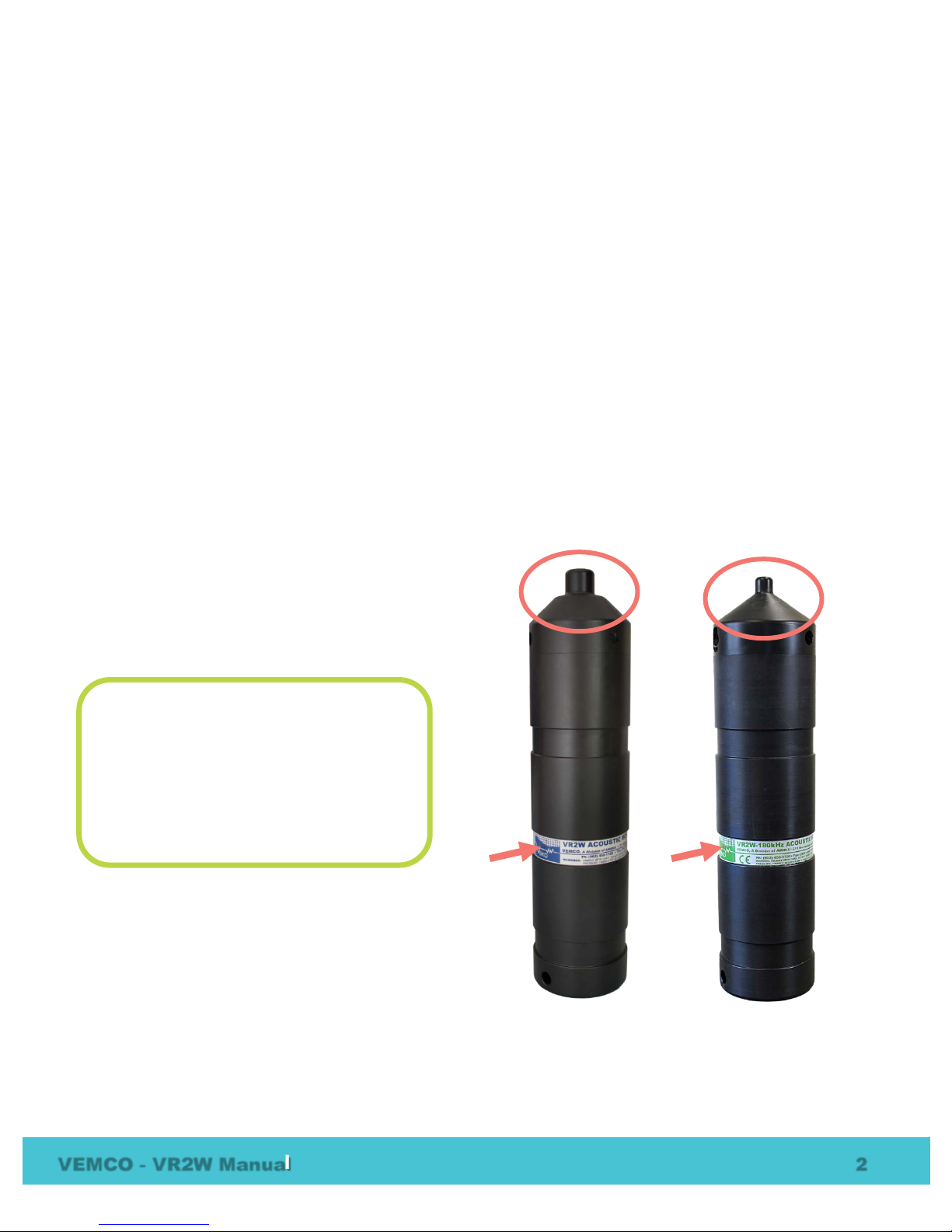
1.2 VR2W Case...........................................................................................................................2
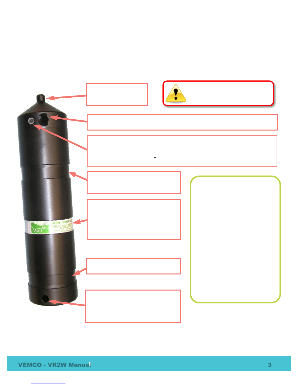
1.3 Case parts .............................................................................................................................3
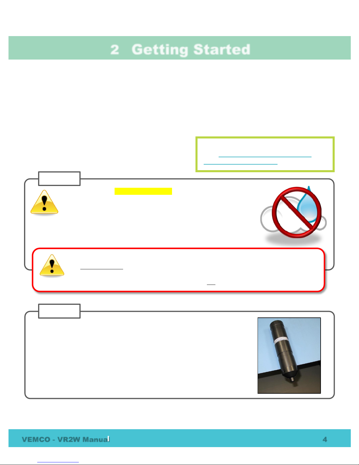
2Getting Started.................................................................... 4
2.1 Open the VR2W Case...........................................................................................................4
2.2 Install Battery.........................................................................................................................7
2.3 Close the VR2W Case...........................................................................................................9
2.4 Testing.................................................................................................................................11
2.4.1 In-Air Test....................................................................................................................11
2.4.2 In-Water Test ..............................................................................................................11
3Communication...................................................................12
3.1 Install VUE software ............................................................................................................12
3.2 Activate Wireless feature.....................................................................................................14
3.3 Establish communication.....................................................................................................15
3.4 Record mode.......................................................................................................................17
3.4.1 Start a Study ...............................................................................................................17
3.5 Offload Data.........................................................................................................................19
3.5.1 Disconnect communication with receiver....................................................................20
3.5.2 Update Firmware.........................................................................................................20
4Deployment .......................................................................23
4.1 Deployment Facts/Tips........................................................................................................23
4.1.1 Mooring.......................................................................................................................23
4.1.2 Spacing.......................................................................................................................23
4.1.3 Biofouling ....................................................................................................................23
4.2 Mooring Line Attachment.....................................................................................................24
5Maintenance ......................................................................26
5.1 Battery Replacement...........................................................................................................26
5.1.1 Disconnecting and Removing Battery.........................................................................26
5.2 O-ring Care..........................................................................................................................27
5.2.1 Remove O-rings..........................................................................................................27
5.2.2 Clean O-ring Surfaces.................................................................................................28
5.2.3 Install O-ring................................................................................................................30
5.3 Storage................................................................................................................................30
6Additional Information..........................................................31
6.1 Flash Memory......................................................................................................................31
6.1.1 Time required to fill memory........................................................................................31

6.1.2 Time required to offload memory ................................................................................32
6.2 LED Flashes........................................................................................................................32
6.3 Set Local options.................................................................................................................33
6.4 Battery .................................................................................................................................34
6.4.1 Battery Life..................................................................................................................35
6.5 Case External Dimensions ..................................................................................................36
6.6 Map Updating ......................................................................................................................37
7Common Questions ..............................................................39
7.1 VUE related questions.........................................................................................................39
7.1.1 How/when do I change my receiver code map? .........................................................39
7.1.2 What is initialization?...................................................................................................39
7.1.3 Why does VUE create two .vrl file types? ...................................................................39
7.1.4 What Date/Time format is my data stored in the receiver and displayed in VUE?......40
7.1.5 What does the “Hide this (window) in future” mean? ..................................................40
7.1.6 How do I open the Options window?...........................................................................40
7.2 VR2W related questions......................................................................................................41
7.2.1 How much detection range can I expect from my tags and receivers?.......................41
7.2.2 How long will my VR2W battery last?..........................................................................41
7.2.3 Does receiver orientation matter?...............................................................................41
7.2.4 At low tide my VR2W receiver will be exposed to direct sunlight, does this matter? ..41
8Troubleshooting..................................................................42
8.1 VUE related troubleshooting................................................................................................42
8.1.1 Bluetooth Troubleshooting ..........................................................................................42
8.1.2 I cannot connect to my VR2W receiver.......................................................................43
8.1.3 These detected ID’s don’t belong to me......................................................................43
8.2 VR2W case related troubleshooting....................................................................................44
8.2.1 The threads have been damaged ...............................................................................44
8.2.2 I think the case might be pressurized..........................................................................44
9Appendix ..........................................................................45
9.1 VR2W Metal/PVC Casing....................................................................................................45
9.2Cleaning Instructions...........................................................................................................47
9.3 Contact Information .............................................................................................................47
9.4 VR2W Specifications...........................................................................................................48
9.5 Warranty and Disclaimer .....................................................................................................49
9.6 Glossary...............................................................................................................................50
9.7 Index....................................................................................................................................51

Regulatory Compliance Information
The VR2W-xxxx-110/111 complies with Part 15 of the FCC Rules. Operation is subject to the
following two conditions: (1) this device may not cause harmful interference and (2) this device
must accept any interference received, including interference that may cause undesired operation
The VR2W-xxxx-110/111 has been tested and found to comply with the limits for a Class B
digital device, pursuant to Part 15 of the FCC Rules. These limits are designed to provide
reasonable protection against harmful interference in a residential installation. This equipment
generates, uses, and can radiate radio frequency energy and, if not installed and used in
accordance with the instruction manual, may cause harmful interference to radio communications.
However, there is no guarantee that interference will not occur in a particular installation. If this
equipment does cause harmful interference to radio or television reception, which can be
determined by turning the equipment off and on, the user is encouraged to try to correct the
interference by one or more of the following measures:
•Reorient or relocate the receiving antenna
•Increase the separation between the equipment and receiver
•Connect the equipment into an outlet on a circuit different from that to which the receiver
is connected
•Consult the dealer or an experienced radio/TV technician for help
Warning: Changes or modification not expressly approved by AMIRIX Systems Inc. could void
the user’s authority to operate the equipment.
© (2014) AMIRIX Systems Inc. All rights reserved. The information contained herein includes
information which is confidential and proprietary to AMIRIX Systems Inc. and may not be used
or disclosed without prior written consent of AMIRIX Systems Inc.
The Bluetooth® word mark and logos are owned by the Bluetooth SIG, Inc. and any use of such
marks by AMIRIX Systems Inc. is under license. Other trademarks and trade names are those of
their respective owners.
WARNING
If the VR2W is not used in the manner
specified by
the manufacturer protection may be impaired.

VEMCO - VR2W Manual 1
1Introduction
1.1 System Overview
The VR2W is a submersible, single-channel acoustic receiver capable of identifying VEMCO
coded transmitters. The receiver operates on a factory set frequency of either 69 kHz or 180
kHz. VR2W receivers can decode uniquely coded pingers and sensor transmitters that operate
on the same frequency as the VR2W.
The VR2W is housed in a corrosion resistant cylindrical plastic high pressure case, and
incorporates an integral hydrophone at the tapered end of the case. The VR2W features include
Bluetooth® wireless technology, a Smart LED, 16 megabytes of data storage, record mode, and
a replaceable battery (single Lithium cell).
The VR2W records the tag code number, the date/time of valid detections, and sensor data if the
tag received is equipped with a sensor. This information is stored in the VR2W memory until it
is downloaded from the receiver using Bluetooth wireless communication and a PC running
VUE software.
Some common uses for VR2W receivers are:
•Monitoring fish movements using acoustic gates across shorelines
•VEMCO Positioning System (VPS) arrays to track animals within a specific area
VR2W Quick Facts
Dimensions 308 mm (12.125") x 73 mm (2.875") diameter
Weight 1190 g in air; 50 g in water
Receive
Frequency
VR2W-69kHz: 69.0 kHz
VR2W-180kHz: 180.0 kHz
Battery Life
VR2W-69kHz: Approximately 15 months
VR2W-180kHz: Approximately 8 months
Memory 8 MB (~0.8 million detections) or
16 MB (~1.6 million detections)
Operating
temperature
-5°C to +40 °C; Water must not freeze.
Maximum
Depth 500 meters (730 psi)
Software VEMCO User Environment (VUE) software
WARNING
The VR2W pressure case and
seal have a maximum
static depth
rating of 500 meters (730 psi).
Physical shocks to the receiver, such as
bumping into a solid object, when it is at
any depth can result in a considerably
higher pressure on the casing than just
the depth pressure and water may enter
the VR2W case. If the O
-rings or their
mating surface
s are dirty or damaged,
then water may also enter the receiver
case. If you are suspicious that water has
entered the receiver, then follow the
suggestions in
section 8.2.2 for
troubleshooting a pressurized case.

VEMCO - VR2W Manual 2
1.2 VR2W Case
The VR2W receiver is housed in the black plastic high pressure case. The case consists of an outer cylinder
that is removed to install the D-cell Lithium battery, and the endcap which houses the hydrophone and
connects to the plastic internal casing. When the outer cylinder is removed, the internal casing protecting the
electronics can be seen. There are two types of internal casing, the older metal/PVC casing and the current
plastic casing. This manual focuses on the current case type; instructions for the older case are found in the
appendix (section 9.1).
A crucial part of the VR2W is the hydrophone, located at the top of the receiver. The hydrophone is similar
to a microphone – it “listens” for sounds and transfers them to the electronics inside the receiver. Be very
careful not to bump the hydrophone or damage may occur that may prevent the receiver from detecting tags.
The VR2W is only capable of listening to one frequency so that frequency must be selected at the time of
ordering. The frequency chosen is based on the coded tags that will be used and can be either 69 kHz or 180
kHz. The frequency is reflected in the name of the receiver, the VR2W-69kHz or the VR2W-180kHz.
Externally there are physical differences between the VR2W-69kHz and the VR2W-180kHz which make it
easier to identify the operating frequency at a glance. The VR2W-180kHz has a smaller hydrophone than the
VR2W-69kHz, and the identification band around the middle of the VR2W-180kHz receiver has green text
while the VR2W-69kHz has blue text. The dimensions of the two cases are slightly different – diagrams are
found in section 6.5.
The cases operate in the same manor so they’ll be
described simply as a VR2W in this manual.
VR2W-69kHz
VR2W-180kHz
Visible External Differences:
1. Hydrophones are different sizes
2. Serial Number label is a different
colour.
Blue = 69 kHz
Green = 180 kHz

VEMCO - VR2W Manual 3
1.3 Case parts
The VR2W is shipped closed, as shown below. The battery may be installed in the case but not connected.
The case only needs to be opened when the battery must be connected or replaced. Connecting the battery is
explained in Section 2, along with opening and closing the receiver case. Replacing the battery is explained
in Section 5.1.
Cable Tie Groove:This is the second
of the two grooves.
Hydrophone: the
receiver’s “microphone”
and most delicate part.
Attachment Hole: This hole, which is
almost 10 mm in diameter, is used with
the Cable Tie Grooves to secure the
VR2W while it is deployed. Section 4.2
has more attachment details.
Cable Tie Groove: These grooves
(there are two) are used to attach the
VR2W to a line – see section 4.2.
Identification Label: Contains product
name and number, contact information,
serial number, and important warnings.
At a glance, the blue text indicates
receiver is a VR2W-69kHz and green text a
VR2W-180kHz.
Comm Key Hole: Place the narrow end of the Comm Key in here to prepare for
communication. Section 2 has more information on the Comm Key.
Status Light (LED)/Release Valve: The light flashes red to indicate the receiver’s
status. Section 6.2 has the full description.
The Release Valve will open if the internal pressure is greater than the external
pressure (see section 8.2.2). Never cover this valve.
Do not bump the hydrophone or
the receiver may be damaged and
unable to detect transmitters.
Status Light (LED) Meanings:
No flashes =
no power
2 quick flashes every 5 sec =
Recording Mode
2 quick flashes every 10 sec =
Memory Full
1 quick flash =
acoustic ping received
1 bright, long flash =
detection written to memory
1 long flash per sec =
Ready for Bluetooth communication
On (solid) =
communicating with VUE

VEMCO - VR2W Manual 4
2Getting Started
Before the VR2W can begin recording detections, it must be powered. VR2W receivers are either shipped
with the D-cell Lithium battery inside the case but not connected to the receiver, or with no battery inside the
case. In either case, the VR2W case must be opened to power the receiver.
2.1 Open the VR2W Case
Two steel rods are necessary to properly open and close the VR2W case. Every shipment of new VR2W
receivers includes a pair of steel rods.
The procedure for opening a VR2W case is the same
regardless of the operating frequency of the receiver.
WARNING
It is vitally important that the electronics inside the receiver case do not come in contact
with any water or the receiver will be damaged.For this reason, VEMCO recommends the
VR2W be opened in a controlled environment and not in the field or on the deck of a boat.
Make sure there is absolutely no water on or near the VR2W case.
Water, even in a small quantity, can damage the VR2W internal circuits
beyond repair. If the VR2W is attached to a wet rope,
remove the receiver fr
om the rope before opening the case.
STEP 1
This also means the electronics cannot be exposed to a sudden change
in temperature and humidity that will cause condensation to develop on
the electronics and destroy the receiver.
Want to watch this? Go to
www.vemco.com/products/vr2w-
69khz/?tutorials-and-tools to see the video.
Place the VR2W on a clean, flat surface so the hydrophone (tapered end) is
hanging over the edge enough that the large hole is past the edge of the
surface. DO NOT let the receiver fall off the surface.
TIP: A non
-slip surface, such as a rubber mat, helps keep the VR2W in place
while opening it.
STEP 2
Continued…

VEMCO - VR2W Manual 5
WARNING
DO NOT impact the threads on the end-cap or they will dent
and prevent the VR2W case from closing. See section 8.2.1
for tips on thread care.
Remove the steel rods from the VR2W case
and set them aside.Be
careful not to let the one in the Comm Key slide through the hole and
cause damage below.
C
ontinue by hand twisting the end-cap in a counter-clockwise
direction until the end
-cap and outer cylinder separate.
STEP 5
Insert one steel rod into the hole that runs through the diameter of the
case near the flat end of the VR2W.
Position it so most of the rod is on
the left side of the
receiver as shown.
STEP 3
Place a hand on the back of t
he receiver to
hold it in place. The back of the receiver
often “jumps” during Step 4 so be prepared.
Insert the other steel rod into the hole in the Comm Key Hole
on the end
-cap of the receiver and hold on to the rod – it will
slide right through the hole and potentially damage
something below.
Make sure the rod is fully inserted into the
hole or damage may occur to the Comm Key Hole.
Apply pressure to
the rod in the COMM Key hole to turn it in
a counter
-clockwise direction when you are facing the
hydrophone. The r
od at the back of the receiver acts as a
brace while you apply pressure
, but be careful of it “jumping”
off the flat surface
.
Continue to r
otate the rod, and therefore the end-cap, until
turning become easier.
STEP 4
Continued…

VEMCO - VR2W Manual 6
WARNING
The internal casing surrounding the electronics is not
waterproof. Water, even condensation from a humid
environment, will enter the case and damage the electronics.
Slide the end
-cap and cylinder apart until the battery compartment has cleared the cylinder. Be very
careful not to damage the threads on the end
-cap or the VR2W won’t close and seal properly.
STEP 6
Plastic Internal Casing
Battery
Compartment
Outer Cylinder
Threads
End-cap
If the VR2W has a metal and PVC internal casing instead of the plastic internal casing shown,
instructions are found in section 9.1.

VEMCO - VR2W Manual 7
2.2 Install Battery
With the case open, you can install the new battery. If there is a used battery in the receiver, use the
instructions found in Section 5.1.1 to remove the battery before inserting the new one.
Some VR2W receivers are shipped with the battery inside
the receiver but not connected. If this is the case for your
receiver, then move to Step 7 in the instructions below to
power your VR2W.
Insert the battery pin into one of the
holes in the edge around the battery
cavity and slide the pin across the end
of the battery until
the ends of the pin
are both in the receiver case.
STEP 3
Downward force
(see red arrow) may
be required on
battery end to get
the pin started.
Slide the Lithium
D
-cell battery into the
battery section at the
end of the receiver so
the battery’s wires are
outside the case.
STEP 2
Check that both
ends of the pin are
flush with the
case.
STEP 4
Place the battery
wires
into the gap in the end
of the receiver case
closest to the battery
connector on the case.
There are two gaps in
the end of the case.
STEP 5
Verify
that the O-ring
inside the battery
cavity is still at the
back of the cavity.
STEP 1
Continued…
Want to watch this? Go to
http://vemco.com/products/vr2w-
69khz/?tutorials-and-tools to see the video.

VEMCO - VR2W Manual 8
Gather any excess battery wire
into the area at the end of
the battery cavity
(circled in yellow) and not along the side
of the receiver casing. This reduces the chance of damage
to the battery
wires.
STEP 8
Place the O
-ring in the O-ring groove around the end of the case so
the
battery wires are inside the O
-ring. This also holds the battery pin in
place.
STEP 6
Position the receiver so you can see the LED light.
Connect the two battery connector halves together until a
“click” is heard and the VR2W receiver’s
light begins
flashing
.
NOTE
: If the VR2W
was in Recording mode (i.e. as Study
had been initialized) when the battery was disconnected,
then it will immediately return to recording detections after
the battery has been replaced. Settings are not lost when
the power is disconnected
.
STEP 7

VEMCO - VR2W Manual 9
2.3 Close the VR2W Case
Before deploying or storing a VR2W receiver, the case
must be properly closed and sealed to prevent damage to
the electronics. Even humidity in the air can, over time,
cause damage to the electronics so it’s very important to
keep the case sealed, with a functioning desiccant pack
inside, as much as possible. Important information about storing a VR2W is found in section 5.3.
Place a new desiccant pack (if the existing one has been deployed) in the
bottom of the
Outer Cylinder so both ends o
f the pack are touching opposite
sides of the cylinder’s wall.
STEP 3
A desiccant pack has been included in the bottom of the
VR2W to reduce the occurrence of
condensation in the
VR2W. One o
f these packs should remain in the receiver
case during storage and deployment.
We recommend that you replace the desiccant pack with
each deployment and with each battery replacement cycle.
More information on the availability and usage of these packs
is located on our website,
www.vemco.com.
Make sure the serial number around the outer cylinder
matches the serial number on the internal casing. This is
particularly important when more than one VR2W receiver is
open at the sa
me time.
STEP 1
If this is the first time closing the VR2W case, then make a visual
ins
pection of the O-rings and the O-ring surface inside the outer
cylinder to be sure
they are clean, properly greased, undamaged,
and debris free.
Details are found in section 5.2.
If the VR2W has been deployed previously, then follow the O
-ring
inspection/replacement instructions in section
5.2 to improve the
seal in the case.
STEP 2
Continued…
Want to watch this? Go to
www.vemco.com/products/vr2w-
69khz/?tutorials-and-tools to see the video.

VEMCO - VR2W Manual 10
Slide the plastic internal casing into the Outer
Cylinder, battery end first, until the first threads
are
inside the outer cylinder. Ensure that the
O
-rings remain
properly seated in
their grooves as the
end
-cap is moved
into the outer
cylinder.
STEP 4
Place the VR2W on a clean, flat surface so the hydrophone
(tapered end)
is hanging over the edge enough that the large hole
is past the edge of the surface. DO NOT let the receiver fall off the
surface.
TIP: A non-slip surface, such as a
rubber mat, helps keep
the VR2W in place while closing it.
Insert one steel rod into the hole that runs through the diameter of
the case near the flat end of the VR2W.
Position the rod so the
majority of the rod is on the right side of the case. This helps brace
the receiver while the case is being closed.
STEP 6
Turn the end-cap in
a clockwise direction
(when looking at the
hydrophone) until it
becomes too hard to
turn
by hand.
STEP 5
Insert the other steel rod into the Comm Key Hole on the end-cap and hold on to the rod – it will slide
through the case and potentially damage something below
. Make sure the rod is fully inserted or
damage may occur to the Comm Key Hole.
STEP 7
Place a hand on the back of the receiver to hold it in
place.
Apply pressure to
the rod in the endcap so it turns in a
clockwise direction when you are facing the
hydrophone.
Continue moving the rod until
the end cap touches the
edge of the outer cylinder. Don’t over
-tighten the case
pieces together or they may be damaged.
Remove the steel rods from the VR2W case.

VEMCO - VR2W Manual 11
2.4 Testing
Before deploying a VR2W, it is wise to test it with a tag to verify that it is
operating properly. This test also creates a VRL file containing all the
configuration information for this receiver – handy to keep as a record of
the receiver’s configuration.
Tests can, and should, be done in both air and water.
2.4.1 In-Air Test
The VR2W can detect coded pingers in air, but at a much reduced range compared to their range capabilities
in water. Perform air tests away from electrical noise sources such as motors, PC screens, or fluorescent
lights.
To perform an in-air test, follow the steps below.
1. Activate the Bluetooth feature on the VR2W (section 3.2).
2. Establish communication between the VR2W and VUE software (section 3.3).
3. Begin a Study. Section 3.4.1 has the details of how to begin a study, also known as initializing a
receiver.
4. Disconnect the wireless communication with the VR2W (click the red box with
the “X” in the receiver ribbon).
5. Activate a tag that operates on the same frequency that the VR2W operates and
place it near the hydrophone. For 69 kHz equipment, place the tag less than 30
cm (12”) away from the VR2W-69kHz hydrophone; for 180 kHz, place the tags
less than 8 cm (3”) from the VR2W-180kHz hydrophone. Position the tag so the
side of the tag is facing the side of the VR2W hydrophone.
6. Wait while the VR2W records the tag(s) near it. You can watch the flash patterns
as the tag is detected and the data is stored in memory. Each faint flash of the
Status Light (LED) is a received ping and a long, bring flash is a stored detection.
If the flash patterns are different, compare it to the Status Light Meanings chart
(section 6.2).
7. Communicate, using VUE, with the VR2W again. Before continuing, take a quick look at the
number of detections and pings received listed in the receiver status information.
8. Offload the data that was collected during the test (section 3.5), creating a VRL file.
9. View the data to verify that the data was stored and retrieved without problems. Instructions for
viewing data are found in the VUE manual.
2.4.2 In-Water Test
Tests performed in water are almost identical to the in-air test explained above. The only difference is that
the tags should be positioned farther from the receivers – 5 meters is suggested. In-water tests are often
performed to establish an ideal range for the VR2W receivers in the environment in which they are moored.
Details of conducting a Range Test are found at www.vemco.com/customer-service/?cs-tutorials.
Perform air tests away from
electrical noise sources such
as motors, PC screens, or
fluorescent lights.

VEMCO - VR2W Manual 12
3Communication
The VR2W uses Bluetooth communication between the receiver and the VUE software. This feature
dramatically increases data offload speed compared to the cabled communication of the retired VR2 receiver.
For example, to offload 2 MB of data requires 3.3 minutes for the VR2W to accomplish but it would have
taken the VR2 more than 75 minutes. A comparison table is located in section 6.1.2 for more information.
Bluetooth is still a relatively new standard and we have observed that not all
Bluetooth devices are created equally or work reliably. To ensure successful
operation with the VEMCO VR2W, we provide our users with a Bluetooth
USB adapter in the VR2W Communications Package that we are confident
will provide reliable functionality.
3.1 Install VUE software
VUE software is used to communicate with the VR2W family of receivers, allowing studies to be setup and
data to be offloaded. The software requires Windows XP SP2, Windows VISTA, Windows 7, or Windows 8.
The Bluetooth USB adapter is required for operation with the VR2W receivers because they use Bluetooth
communication. Others receivers may not use Bluetooth communication and therefore would not need the
USB adapter.
NOTE:
Due to Bluetooth characteristics
in water, the VR2W must
communicate with the Bluetooth
USB adapter through air
(typical range is 10 meters).
Run the latest “Install_VUE
”
application file. The latest file
is always available from our
website,
www.vemco.com.
STEP 2
Click “Next” when the
Install Shield Wizard
begins.
STEP 3
Attach the VEMCO supplied
Bluetooth® USB adapter (may not appear as
shown)
to any USB port on your PC. If the “Found New Hardware Wizard”
window opens, which may happen if your PC uses Windows XP or Vista,
then select “Cancel” and continue with these instructions.
STEP 1
If you are using Windows XP or Vista, then you must install VUE
2.0.6 or greater for the proper adapter drivers. Windows 7 and
greater have the necessary drivers installed.
Continued…

VEMCO - VR2W Manual 13
If you are opening a database created by an earlier version of VUE (version 1.4.4 or older), you will receive a
warning that the database will be converted to the new version of VUE and will no longer be compatible with
older versions of the software.
Read the license
agreement and select
“I accept” and “Next”
if you agree to the
terms.
STEP 4
Click “Next” to install
VUE in the folder
shown, or click
“Change” to select a
difference folder.
STEP 5
Wait while the VUE
software is installed.
Click “Next” when it
becomes enabled.
STEP 6
Click “Finished” to exit
the setup wizard.
STEP 7

VEMCO - VR2W Manual 14
3.2 Activate Wireless feature
The Bluetooth feature in a VR2W receiver must be activated before the VUE software will be able to find and
connect to the VR2W. Activation requires a specially designed Communications Key (also referred to as
“Comm Key”).
The Communications Key is a stepped cylinder made of black plastic material. A strong magnet is contained
in the smaller end of the Comm Key and should be kept away from any magnetically sensitive materials. An
orange float is attached to the Com Key case for easier handling and locating of the key. This key functions
with other VEMCO receivers that use a Comm Key, such as the VR4-UWM.
The flash pattern in a VR2W indicates the mode (state) the receiver is in at the time. A bright, long flash
once a second indicates that the VR2W is now ready for wireless communication but is not yet in
communication with VUE.
The Comm Key can be removed from the VR2W once the light is flashing.
WARNING
The Communication Key contains a
strong magnet. Do not put it near
magnet-sensitive materials, such as
CRT computer monitors or magnetic
stripes, as they could be seriously
damaged.
TIP
It’s helpful to place the VR2W within 10 meters (32 feet) of the
operating Bluetooth® USB adapter before activating the VR2W.
MAGNET
FLOAT
COMM KEY
Wait until the VR2W’s LED
begins flashing
a bright,
long, steady flash once a
second. The
wait time is
less than
five seconds.
Remove the Comm key.
STEP 2
Bright flash
every second
Slide the smaller end
of the Comm Key in
the Comm
Key Hole
on the VR2W, near
the hydrophone.
STEP 1

VEMCO - VR2W Manual 15
3.3 Establish communication
After the VR2W has been activated (section 3.2), it is ready for wireless communication with the VUE
software. The VR2W must be within communication range of the Bluetooth USB adapter, which is typically
10 meters (32 feet) but can vary based on physical and wireless
obstructions/interference.Due to Bluetooth® wireless technology
characteristics in water, the VR2W must communicate to the Bluetooth®
USB adapter through air.
VR2W communication range:
10 meters (32 feet) through air
from Bluetooth® USB adapter.
Open the VUE software. The software will scan for any active devices
within communication range.
Wait while the software searches for receiver
s.
STEP 1
All Bluetooth® activated VEMCO receivers within
communication range will be displayed when a Device
Scan is performed.
When the software finds the receiver, a VR2W icon will be
displayed in the “Bluetooth Devices” section of the Home
tab with the receiver’s serial number for identification. It
will display all
Bluetooth® activated receivers (LED is
flashing bright, long, steady flashes) within communication
range
, which is approximately 10 meters.
If wireless communication has not been activated on the
VR2W, then activate communication (section
3.2
) and click
“Device Scan” on the VUE software’s Home tab.
Wait while the software searches for receiver
s.
TIP: If VUE can’t find your receiver(s), try again. It’s
not uncommon for a Bluetooth scan to miss devices,
especially if other wireless devices are in the area.
Double
-click on the receiver icon of the desired VR2W (serial number is listed under the icon)
and wait while communication is
established. You’ll know communication was successfully
established when information pertaining to this receiver is displayed and the receiver’s LED is
on continuously
. The “Link Status” in the VUE window also changes to “Connected”.
STEP 2
TIP: VUE can communicate with up to seven wireless receivers simultaneously.
Other manuals for VR2W
2
Table of contents
Other Vemco Receiver manuals
Popular Receiver manuals by other brands

Erone
Erone SEL2641 R433-IP quick start guide

Harman Kardon
Harman Kardon AVR 1550 Service manual

Wisenet
Wisenet SBP-300HM6 quick start guide

Harman Kardon
Harman Kardon AVR 525 Service manual

Grandstream Networks
Grandstream Networks HT801V2 Quick installation guide

PureTools
PureTools PT-HDBT-1020HU-RX user manual