VENDINGBOX 540 User manual

Vending-Box COMPANY Model 540
Thank you for choosing the Vending-Box Company
device. The aim of the following manual is to
familiarize the user with operating and functions of the
device.
Vending-Box Company allows to copy this manual only
as whole since it forms am integral unity.
The device and the screenshots used in the manual
may differ from the actual device. Accessories added to
the device may look different from the ones illustrated
in this manual. The latest version of the manual can be
found on the Vending-Box Company webpage:
http://www.vending-box.com.
The producer reserves the right to modifying the
properties of the equipment described in the manual
without giving earlier information and does not take
responsibility for any errors in this document being the
result of inappropriate printing.
EXPLANATION OF SYMBOLS
In order to emphasize important information, there are
two ways of presenting important information in the
text. The first one refers to safety tips.
Other important information which need special
attention are marked in the following way:
Safety tips are marked with a warning triangle
and gray patch lined with horizontal lines above
and below the text.
The tips in the text are marked with this symbol.
They are lined with horizontal lines above and
below the text.
The words in bold are entries explained in the glossary.
GLOSSARY
DISPENSING POINT
a group of devices within which there is one master
device equipped with the user’s interface, controlling
work of other devices. In the managing application, the
group of devices is displayed as one block. The most
basic case is when the dispensing point is formed of
only one master device.
USER’S INTERFACE
a panel in the right door of the dispenser, used for
communication between a person and the machine. It
contains a display, group of buttons and proximity card
scanner.
MASTER DEVICE
a device which is a part of VNET net devices,
responsible for general control .
SUBORDINATE DEVICE
a device which is an extra equipment for the master
device, controlled by it and completely dependent on it,
with no possibility of functioning independently.
MANAGING APPLICATION
program which enables to manage a group of dispensing
points, installed and started on Vending-Box or Client’s
servers.
ROTATING FEEDER
central part of the device whose role is to store products.
The feeder which is also called ‘a drum’ consists of a
set of cells.
PRODUCT CELL
limited room for keeping products in the feeder.
PROXIMITY CARD
an individual user’s card for automatic identification.

Vending-Box COMPANY Model 540
GLOSSARY
GENERAL INFORMATION .............................................................................................................................................5
Important information on safety.......................................................................................................................................5
Use of the device..............................................................................................................................................................5
In case of failure ..............................................................................................................................................................5
Identification of the device ..............................................................................................................................................5
The machine construction................................................................................................................................................5
General view.................................................................................................................................................................6
Inner front panel .........................................................................................................................................................6
Back of the device .......................................................................................................................................................6
User’s panel controller..................................................................................................................................................6
Transport..........................................................................................................................................................................7
Environment protection....................................................................................................................................................7
INSTALLATION OF THE DEVICE..................................................................................................................................9
Location of the machine .................................................................................................................................................9
First start-up ....................................................................................................................................................................9
Starting the device............................................................................................................................................................9
ETHERNET..................................................................................................................................................................9
WLAN..........................................................................................................................................................................9
Packet data GPRS connection ....................................................................................................................................10
Time set correctness ...................................................................................................................................................10
VPN connection..........................................................................................................................................................10
Device data reading ....................................................................................................................................................10
Starting the dispensing application.............................................................................................................................10
Switching off the device ..............................................................................................................................................10
CONFIGURATION OF THE DEVICE............................................................................................................................11
Configuration of the feeder............................................................................................................................................11
Change of the width of the product cell......................................................................................................................11
Regulation of the width of opening sliding flaps........................................................................................................11
Configuration of the feeder in the user’s panel/assigning the product........................................................................11
Replacement of the SIM card.........................................................................................................................................11
Configuration of net interfaces .....................................................................................................................................12
ETHERNET interface.................................................................................................................................................12
WLAN interface .........................................................................................................................................................12
Interfejs GSM .............................................................................................................................................................12
LOADING AND DOWNLOADING PRODUCTS..........................................................................................................13
Loading..........................................................................................................................................................................13
Loading through flaps.................................................................................................................................................13
Loading according to the loading scheme ..................................................................................................................13
Product downloading .....................................................................................................................................................14
MAINTENANCE..............................................................................................................................................................15
Cleaning and conservation.............................................................................................................................................15
Periodic inspection.........................................................................................................................................................15
List of spare parts ..........................................................................................................................................................15
Parts being the subject to replacement........................................................................................................................15
Replacement of consumable elements ........................................................................................................................15
Replacement of the battery.........................................................................................................................................15
Replacement of the RCT (Real Time Clock) batteries ............................................................................................15
The parts required during the reconfiguration of the machine. .....................................................................................16
GUARANTEE...................................................................................................................................................................17
Guarantee conditions......................................................................................................................................................17

Vending-Box COMPANY Model 540
GENERAL INFORMATION
1Important information on safety.
Please refer to the following tips. Non-compliance with
the instructions may be dangerous or illegal.
The machine is constructed in such a way that the
feeder cannot rotate after the door is open, except for
the situation of the user’s purposeful operation as well
as when the sliding flaps are open. In case of damage of
the elements of the door, especially of the sensor of
door opening, sliding flaps or any covers, he machine
must be immediately disconnected from the power
supply.
The device may be repaired only by the qualified
Vending-Box service or authorized service. Repair by a
non-qualified service or non-authorized service can
result in the machine damage and loss of guarantee.
This device is not waterproof. It must be protected from
moisture.
The battery cannot be exposed to very low or very high
temperatures (below -15°C /5°F or above 40°C / 104°F).
Extreme temperatures may affect the volume and
durability of the battery. The battery should also be
protected from liquids and metal objects. This kind of
contact may partly or entirely damage the battery. The
battery is to be used only for its intended purpose. You
must not destroy or damage the battery or throw it to
fire –it may be dangerous and cause a fire. Used or
damaged battery should be put in a special container.
You must not open the battery. Installation of a battery
of an inappropriate type may cause fire or explosion.
The device is a class A product, it may cause
disturbance in radio waves, which will need
undertaking action by the user.
2Use of the device
540 dispenser is a combination of an automatic
dispensing cabinet and managing software.
The system solves the problems of managing and
dispensing of many types of products for industrial and
other purposes in production places.
The use of the system of dispensing management with
the use of 540 dispenser facilitates analysis and control
of all the distributed items, ensures safety and
availability of products 24 hours a day, 7 days a week
without additional cost of storing and manual
distribution.
3In case of failure
In most cases any technical problems are fixed on the
way of minor repairing operations. However, before
contacting the producer, careful reading of the following
manual is recommended. If any serious failure occurs,
contact an authorized service.
4Identification of the device
Each machine is identified by a unique serial number,
which can be found on the rating plate fixed to the back
of the device, at the bottom part. The rating plate
includes data, which allow the user to define basic
parameters of the device, such as electric parameters or
the dispenser’s weight.
The rating plate includes information on :
1. data of the producer
2. name of the device
3. information on power supply
4. CE marking
5. maximum power consumption
6. weight
7. unique serial number
8. year of production
5Parameters
Dimensions
Height
1915 mm
Width
805 mm
Depth
790 mm
Weight
400 kg
Permissible weight
275 kg*
Range of work
temperature
5-40 / -15-40 °C**
Relative humidity
do 80%
Power
Voltage
230 VAC
Frequency
50Hz
Maximum current
1A
Power consumption
25 W / 150
W***
Communication
interfaces
Ethernet
Wi-Fi
GSM
VNET
Accepted proximity
cards
125kHz
Unique
Hitag
Q5
HID
13,56 MHz
MIFARE®
Classic
MIFARE®
Plus
MIFARE®
Ultralight
MIFARE®
Ultralight C
MIFARE®
DESFire
MIFARE®
DESFire
EV1.
*maximum load of a single loading shelf 0,5kg
**version with extended range of working temperatures
***average power consumption/maximum momentary
power consumption

Vending-Box COMPANY Model 540
6The machine construction
During the 540 dispenser was being designed, our aim
was to design a device which would be easy to operate
and maintain. Because the device is an industrial
facility, whose functionality must be immediately
restored in case it works inappropriately, it has a module
construction. The main components like power supply
unit, drive, left or right door can be easily replaced with
a spare component.
General view
The dispenser has monolithic, cubic construction. In the
front part, there is a double-leaf, asymmetrical door.
The left door leaf is opened with a key supplied with the
device. In this door, there is a range of sliding flaps
which ensure controlled availability to the feeder cells
from outside and which includes all the
electromechanics of the flaps and steering electronics.
The right door is opened after loosening two safety
screws, which are inside of the machine by the door’s
left edge at both the top and bottom of the door. In the
right door, there is a controller of the user’s panel and
the panel.
Below: the display of the general view of the device.
1. upper hinge of the door,
2. left door,
3. sliding flap,
4. tappet for the door sensor,
5. left door controller,
6. drum brake,
7. power supply unit,
8. front panel,
9. rotating feeder,
10. main driver,
11. adjustable foot,
12. cover of the controller of the user’s panel
13. right door,
14. Wi-Fi antenna,
15. GSM antenna.
On the upper cover of the machine, there are two
antennas for radio communication. In order to
make the radio interfaces work properly, you must not
place metal elements nearby, particularly the antennas
must not be covered with any elements.
In the lower part of the device, there is a module of the
power supply unit, main driver, drum brake and drive
module installed inside the device in its back part.
The central element is the rotating feeder whose role is
to store the distributed items. The construction of the
feeder enables its easy configuration in order to adjust
the size of the item storing cells.
6.1 Inner front panel
All switches and use sockets are inside the device on the
front panel, at the bottom of the machine. Their exact
location is showed below:
1. Fuse socket F1
2. Fuse socket F2
3. Main switch
4. Switch for semi-automatic feeder rotation
5. Sensor of the right door opening
6. Fuse socket F3
7. VNET gate address adjuster
6.2 Back of the device
At the back of the machine, there is a range of
connection sockets whose role is to supply power to the
device, connecting it to the ETERENET and connecting
subordinate devices with the use of VNET bus. Here is
also the rating plate thank to which the device and its
parameters can be identified. The exact location of these
elements is showed below:
1. VNET bus connectors
2. ETHERNET connector,
3. Power supply socket,
4. Rating plate panel

Vending-Box COMPANY Model 540
The connection of the power supply
through the socket at the back of the
dispenser is an emergency stop switch because of
lack of access to the min switch when the
dispenser door is closed. Remember to ensure an
access to the power supply cable so that it can be
disconnected any time
6.3 User’s panel controller
The controller is responsible for the user’s panel
functioning. It is located on the inner side of the right
door. It is protected by a cover, which can be removed
with the use of a cross-head screwdriver.
1. SIM card socket with a lock
2. 3V battery
3. Power supply diode
6.4 Touch Panel
The basic interface used for communication with the
device is the user’s panel located in the right door of the
dispenser. The view of the panel is showed below:
1. Function touch button,
2. User’s panel display,
3. The scan field of proximity card reader
For identification of the user, there is a proximity card
reader located below the display behind a glass panel.
Depending on the reader, the range of the scan field is
from a couple to several centimeters. All information
for the user are displayed on the 7’’ screen. On both
sides of the screen and below it, there are fifteen touch
buttons. Functions of the buttons depend on the
information displayed on the screen. The touch buttons
react to human fingers’ touch. It is possible to touch the
buttons in thin gloves but it may make the quality of the
operation worse. You must not use a stylus or other
pointing elements, which might not be recognized by
the touch buttons, and in particular situations they may
scratch the surface or even break the glass surface of the
user’s panel.
7Transport
Original package secures the device against abrasion or
minor hits. However, in order to avoid damages,
particular safety measures should be taken
during transportation. The device is adjusted to
transportation directly by a forklift.
The device may be lifted on each side. However,
remember that the fork of the forklift is placed under the
whole machine and extends out of its contour.
During transportation and storing, no other objects may
be placed on or in the device.
In transportation of the device, because of possible
vibrations and inertia of the rotating feeder, the brake
should be unlocked so the drum could rotate freely.
Otherwise the brake lock mechanism may get damaged.
It is recommended to be careful when placing
the machine on the floor. It should be done
gently in order to avoid excessive shock.
Even when placing the device in the final destination, a
forklift or pallet truck matching the device weight and
dimensions should be used. You must not move the
machine.
Because the center of gravity is located high, it
is necessary to fix the device for transportation
with securing belts. Before lifting the machine,
make sure if its weight is within the range of the used
lift. Information on the weight of the device is to be
found on the rating plate.
In case of longer storage of the machine, it is
recommended to periodically (every second month)
connect the device to the outer power supply for 48
hours in order to charge the battery installed in the
machine.
8Environment protection
All the parts should be utilized
according to the standards of
environment protection.
The proper utilization enables
preserving valuable natural
resources and avoiding negative
influence on health and
environment, which may be
endangered by inappropriate waste
proceedings.

Vending-Box COMPANY Model 540
The device together with its package should undergo
recycling.
Illegal utilization is the subject to penalties.
European Union countries
Devices marked with this symbol should not be utilized
together with municipal waste. More information may
be obtained from the producer.
Non-European Union countries
The owner of the device should contact local authorities
in order to obtain information on the appropriate
utilization.
INSTALLATION OF THE DEVICE
9Location of the machine
The machine is not intended to be used outdoor. It must
be located in a dry indoor place and it must not be
moisturized by any water or other liquid drops. If the
machine is equipped with radio communication
systems, all metal objects must be placed in the distance
of at least 1 metre from the machine.
10 First start-up
Before the first start-up, it is obligatory to get familiar
with this manual. If the information included in it is not
precise enough, please contact the producer’s service.
All procedures described in this chapter should
be done with the machine disconnected from the
power supply.
Before starting up the device, you must check technical
condition of the machine, if it has not been damaged
mechanically in transport. In case you find any damage,
it must be assessed if it affects safety and if it might
limit the functioning of the device. If so, any starting-up
procedures should be stopped.
If you are not able to define the device
condition or you have no qualification to assess
if the damage might cause any danger to the
user, contact an authorized
First thing to be done after placing the machine in its
final destination is to level it with the help of four
levelling feet, which are supplied with the device. While
placing the machine vertically, use an appropriate lift.
Do not lift the device with the use of the levelling feet.
Next step is regulation of the left and right door hinges,
which could be moved in transport. To do it, you
should use upper hinges fixed with tree screws each,
two from the top and one accessible from the inside of
the machine. To get access to the inner screws, you
must open the device.
Hinge screws should be only loosened and after
regulating the hinge, they should be screwed so that the
hinge could not be moved during opening the door.
After regulation, the space between the doors should not
be bigger than 3 mm, equal along the door edges. The
outer edges of the doors should fit the contour of the
shell of the machine. After the right door is blocked,
you must check if the sensor of the left door opening
switches after it is closed. You should hear a clear click
of the sensor pins. If after closing the door, the switch is
not on, you must move the tappet of the door sensor
located on the left door so that the sensor is clearly
switched on after the door is closed.
The door opening sensor is one of the elements
responsible for safe work of the machine. In
case it is not switched on after closing the left door,
feeder rotation will not be possible.
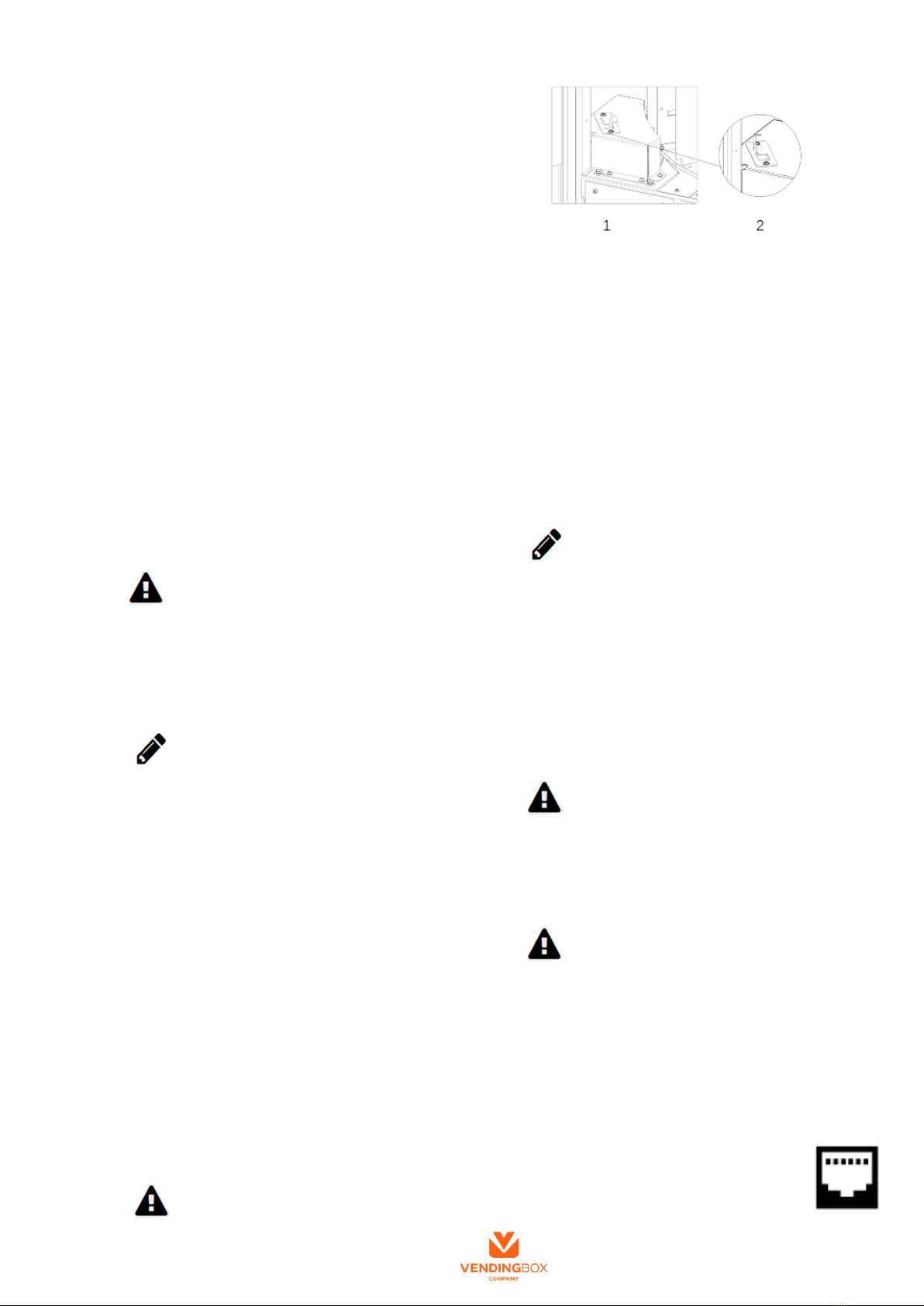
The last thing which should be done before starting up
the device is verification of the free feeder rotation. To
do it, you must unlock the drum by pulling the brake rod
away from the feeder and pushing it away from you so
that the rod gets blocked in the gap of the brake shell. In
the picture you can see the view of the brake in the
position blocking the rotation of the feeder (1) and in
the position of the blocking mechanism pulled in (2).
After unlocking the drum, the feeder may be rotated
manually. Give the drum a full turn checking if the
movement is free and no alarming noises come out of
the machine which could mean that the drive
mechanism might be damaged. If you notice
inappropriate work of the feeder, stop the device
starting-up.
If you are not able to define clearly the state of
the feeder’s work, contact an authorized service.
If the condition of the machine is verified, the device is
leveled, door suspension is regulated and the feeder
rotates freely, the machine is ready to be started. More
information on this subject can be found in the chapter:
Starting the device.
11 Starting the device
If the device has been transported or has not worked for
a longer time, follow the procedure described in the
chapter: First Start-up.
In order to start the device, first you must plug it in the
power supply. Connecting the machine with the power
supply of 230VAC should be done when the
main switch is in the 0 position.
The connected device must be laced behind the
ground-fault circuit and the power socket must enable
connection with PE conductor.
After connecting the machine with the power supply
and switching on the machine with the main switch
(position 1), the device will be started.
Switching on the power supply, with the
opening door sensor turned on causes automatic
rotation of the drum in order to set its position.
Remember not to leave protruding elements in the
feeder and to move aside from the feeder after switching
the machine on.
After a short while, the display shows start-up screen
with description of the model of the machine and a
variety of status icons informing about the state of
starting-up.
11.1 ETHERNET
The first one to be started is the
ETHERNET interface. This showed icon
informs about the connection with the net. If
the connection is successful, the icon color
will change from gray to blue.

Vending-Box COMPANY Model 540
Extra information on ETHERNET connection
configuration is to be found in the chapter:
Configuration of net interfaces.
11.2 WLAN
The second step is starting the WLAN
interface. This icon informs about the state
of connection with the net. If the connection
is successful, the icon color will change from
gray to blue. If the WLAN interface is
switched off, this stage is omitted. The wireless net
interface is not supplied with the standard equipment.
Extra information on WLAN connection configuration
is to be found in the chapter: Configuration of net
interfaces.
11.3 Packet data GPRS connection
The last net interface started is the GSM
modem for connection of packet data. This
icon informs about the state of connection
with the GSM net. The status information
shows the signal strength, 0-4 bars and the
state of packet data connection. If the connection is
successful, the edging will change the color from gray
to blue. If the GSM interface is switched off, this stage
is omitted.
Extra information on GSM connection configuration is
to be found in the chapter: Configuration of net
interfaces.
11.4 Time set correctness
Next step is verification of the time set in the
Real Time Clock (RTC). In case of
discharging or damaging the battery, the
device will download the current time from
the configured time server using the
connection with the internet. While downloading the
information on the current time from the internet, the
device informs about it generating three short sound
signals.
If downloading the current time from the server is
necessary, it is essential to set the connection with the
internet with the use of ETHERNET, WLAN or GSM.
If the verification of RTC time is successful, the icon
will change the color from gray to blue.
11.5 VPN connection
Next step is connection with the VPN
(Virtual Private Network). The showed icon
informs about the state of connection with
the net. If the connection is successful, the
icon color will change from gray to blue. If
the VPN connection is switched off, this
stage is omitted.
11.6 Device data reading
Finally, reading and verification of data
recorder in the non-volatile memory of the
device. If the operation is successful, the
showed icon will change from gray to blue.
11.7 Starting the dispensing application
After correct introduction of all the active steps of the
starting screen, dispensing application is started. The
default screen after starting is the screen of waiting for
the user’s logging in with the use of the proximity card.
After starting the application, the device is ready to
normal work such s dispensing, loading or configuration
described in chapter: Configuration of the device.
12 Switching off the device
To switch off the device, you must turn the main power
supply switch to the 0 position. In the emergency
situation, the machine may be switched off by
unplugging it from the power supply socket, at the back
of the machine.
After disconnecting from the power supply, the
controller of the user’s panel is powered from the
battery and produces a sound signal for about a minute,
informing about power disconnection. If the power is
supplied back within this time, the machine will
immediately restore its work.
Switching on the power supply with the opening door
sensor switched on causes automatic rotation of the
drum in order to set its position. . Remember not to
leave protruding elements in the feeder and to move
aside from the feeder after switching the machine on.
If the power is not supplied back, the machine will stop
producing the sound signal and will get switched off. If
the power is supplied when the machine does not
produce the sound signal any longer, all the starting-up
procedure described in the previous chapter will occur.
Emergency power supply is realized with the use of
installed battery. The battery used is able to ensure
maintaining the operation of the controller four times
per day at the minimum, after power disconnection, for
all the cycle of the battery durability.
CONFIGURATION OF THE DEVICE
13 Configuration of the feeder
Product cells may differ in size. The user has a
possibility to individually adjust the size of shelf to the
product even when the machine is already in use. In the
feeder of the 540 dispenser you can set 6 different sizes
of product cells.
Selecting a cell type, you must set it for the whole level
in the feeder. It is not possible to set two or more
different sizes of product cells on one level. Changing
the width of a cell, you
must properly set also the
element defining the
opening width of the
sliding flap.
The chart below shows all
available types together
with dimensions and
number of cells for each
type setting in the whole
feeder.
Number of
cells
A
B
C
D
540
80mm
75mm
275mm
15mm
270
80mm
150mm
275mm
30mm
270
170mm
75mm
275mm
15mm
180
260mm
75mm
275mm
15mm
135
170mm
150mm
275mm
30mm
90
260mm
150mm
275mm
30mm
It is possible to change the height of product cells
during the use of the device. However, this kind of
reconfiguration can be done only by an authorized

Vending-Box COMPANY Model 540
service or a qualified technician.
For each level of the feeder we can match a product
which will be dispensed from it. Such matching forms a
scheme of loading for a certain level. Thank to matching
a product to a level and forming such a scheme of
loading, we can load this space with products directly to
the feeder through an open left door-leaf.
13.1 Change of the width of the product cell
In order to make the
product cell wider, on the
selected level you must
remove a blocking dowel
(1) of certain partition (2)
and pull it out completely.
To install additional
partition, you must do this
in the reverse order.
If a new partition is installed, set it so as the
blocking dowel prevented it from falling out.
A bigger notch in the front part of the partition
makes it possible to pull out the dowel in the cell below.
13.2 Regulation of the width of opening sliding
flaps
The width of opening of the sliding flaps depends on the
element of the lock limiting
full opening (1). If full
opening of the flap and 15
cells on the level re needed,
the cap covering the lock
must be removed. To set the
width of opening the flap to
the ½ width, the blocking
element must be screwed
and covered with a plastic
cap.
13.3 Configuration of the feeder in the user’s
panel/assigning the product
In the menu of configuration of the feeder, it is possible
to set a scheme of loading and size of the product cell
for each level of the feeder.
In the picture below you can see two levels of the
device marked 1 and 2. On the level 1, the width of the
opening of loading window is set to ½, there are 30 cells
on the level. In this case a product for loading scheme
has not been selected so this level can be loaded through
flaps. There is no possibility of product loading directly
to the drum.
For the level 2, the full width, 15 cells for the level and
a certain product matched have been set. Next to the
product icon, its category, defined type and name are
displayed, and we can see the number of items of the
certain product matching this level, here it is 15.
In order to change the width of the product cell, you
must select the proper configuration, pressing the button
on the chosen level on the left side of the panel. To
match or cancel a product for a certain level, you must
press the button on the right side of the panel.
In order to make the dispenser work properly, the width
of cells must be set according to physical configuration
of the feeder, and products must be matched with
certain levels according to the needs.
To install or replace the SIM card, flat key
10mm and cross-head screwdriver are needed.
Before replacing the SIM card, the machine
must be switched off. The device produces
short, regular sounds informing that data is
recorded. After recording the data, you must wait 30
seconds.
During removing the cover, you must be careful not to
damage the controller.
14 Replacement of the SIM card
The SIM card socket is located on the controller plate of
the user’s panel. To replace the SIM card, screws fixing
the cover of the controller of the user’s panel must be
unscrewed.
Insert the SIM card to the tray. Unlock the tray
moving it slightly towards OPEN and then
move outside of the socket. Insert the SIM
card so that the cut off corner of the card fitted
the cut off corner of the socket. Close the tray with the
installed SIM card and lock , moving it towards LOCK.
1. Cut off corner,
2. SIM card tray
After installation of the SIM card, fix carefully the
cover of the user’s panel controller.
To ensure the proper work of the SIM card, configure
the settings of the net interfaces. There is a detailed
description of it in the chapter: 3.3 GSM interface.
15 Configuration of net interfaces
Configuration of the parameters of net interfaces is
possible to be done in the menu of advanced settings,
accessible only for a user like serviceman. The device
may be equipped with maximum three net interfaces:
ETHERNET, WLAN and GSM and the equipment for
connection with the ETHERNET and GSM is standard
one with every device. After introducing changes in the
menu of the advanced settings, the machine should be
updated.

Vending-Box COMPANY Model 540
15.1 ETHERNET interface
In order to configure Ethernet interface, match the right
values with the parametres below:
NAME
Description
ETH
Defines if the interface is on. Admissible
value YES or NO.
ETH_AD
DR
IP address of the device in X.X.X.X or
DHCP in case of the dynamically
assigned address.
ETH_MA
SK
Net mask in X.X.X.X. Ignored parameter
in case of switching on the client’s
DHCP.
ETH_G
W
IP address of the gate in the net in
X.X.X.X. The parametre is ignored in
case switching on the client’s DHCP.
All the predefined text values should be typed in capital
letters.
15.2 WLAN interface
In order to configure WLAN interface match the right
values with the parametres below:
NAME
Description
WLAN
Description
WLAN_
ADDR
Defines if the interface is on. Admissible
value YES or NO.
WLAN_
MASK
IP address of the device in X.X.X.X or
DHCP in case of the dynamically
assigned address.
WLAN_
GW
Net mask in X.X.X.X. Ignored parameter
in case of switching on the client’s
DHCP.
WLAN_S
SID
IP address of the gate in the net in
X.X.X.X. The parametre is ignored in
case switching on the client’s DHCP.
WLAN_P
ASS
Name of the wireless net, which the
device is to be connected with.
All the predefined text values should be typed in capital
letters.
15.3 Interfejs GSM
In order to configure GSM interface, match the right
values with the parametres below:
NAZWA
Description
GSM
Defines if the interface is on. Admissible
value YES or NO.
GSM_A
CCN
Access number.
GSM_A
PN
Name of the access point.
GSM_PI
N
PIN number of the SIM card.
GSM_S
MS
Defines if during connecting, the text
messages are to be deleted from the
SIM card. Admissible value YES or NO.
All the predefined text values should be typed in capital
letters.
Configuration of the connection of packet data
depends on the operator and the tariff plan. If you do not
know the settings needed for connection through GSM,
contact an operator of the net which the used SIM card
In case of wrong PIN code, the SIM card may be
blocked. Before you start transmission of packet data,
make sure the given PIN code is right.

Vending-Box COMPANY Model 540
LOADING AND DOWNLOADING PRODUCTS
1Loading
The feeder may be loaded with products in two different
ways. The firs one is loading the feeder through flaps,
the second one is loading with a scheme, and in this
case a product is matched with a certain level of the
feeder. In order to have access to the loading function,
in the user’s account you must set his type to
either LOADER or SERVICEMAN.
Available ways of loading the feeder are in the menu of
loading showed below:
1.1 Loading through flaps
In the mode of loading thorough flaps, it is not
necessary to open the machine. Products are loaded
through sliding flaps unlocked automatically for empty
product cells. To start loading through the flaps, choose
this mode in the menu of loading.
Before starting to load, make sure that the door of the
machine and the sliding flaps are closed, otherwise there
will appear appropriate information on the screen.
On the screen there will appear the menu showed in the
further part of this chapter. At the top you can see
information about the product which is currently being
loaded. To change the loaded product, press the button,
either the left or the right one which is at the height of
the data about the product, and select the one which is to
be loaded. The device automatically unlocks these
sliding flaps, for which the product cells are empty. The
LED diode, which is on the left, informs about the state
of the flap lock. The red color means the flap is locked,
and the green color means the flap is unlocked and
ready for loading, the orange color means the flap is
unlocked, open but treated as loaded.
The user may open unlocked flaps and load the cells
with a chosen product. If all empty cells are loaded or
there are no more empty cells of the needed dimensions,
the user may turn the feeder selecting he button NEXT
FREE COLUMN in the menu. The device will prepare
the first available column in which there is at least one
empty cell.
If the function DELETEOPENINGS is used, but you do
not want to delete all the openings, leave such flaps
open in the moment of pressing DELETE OPENINGS.
If the user opens the flap, but does not have a product
which could be put in the empty cell, it is possible to
delete the information about the flap opening and
product loading. In this case, select the button DELETE
OPENINGS, the closed flaps, which were opened
before, will be treated s unloaded and the orange diode
will become green.
The user can change the loading product any time. In
case of loading a few kinds of products, the sequence of
loading described above should be carried out for each
product separately.
1.2 Loading according to the loading scheme
Loading according to the loading scheme means loading
the drum with products matched with certain levels
through the open door. To do it, open the machine in
order to have a direct access to the feeder.
To have an access to the whole loading space in the
feeder, you must turn it manually or in the semi-
automatic mode. The manual turning of the feeder is
possible after unlocking the drum brake as it is
described in the chapter: First start-up. Semi-automatic
turning of the drum is carried out with the use of the
switch left-right which is inside the device in its lower
part. To activate this function, pull the moveable
element of the door sensor.
Products should be loaded according to the loading
scheme, whose setting is described in the chapter:
Configuration of the feeder in the user’s panel/
matching the product. Products are to be loaded from
the position 1 upwards. If a certain level is not fully
loaded, leave empty space in the last partitions of the
level. It is not necessary to load all the levels available
in the loading scheme.
After product loading to the feeder is finished, enter the
current number of products on every completed level.
To do it, use the screen accessible after selecting the
option ENTER THE LOADED NUMBER in the menu
of loading. On this screen there will appear all levels
with the set loading scheme as it is shown below:
If ,for any reason, we do not add products on a certain
level, do not replace them so that the empty space is at
the end of the loading space of the level.

Vending-Box COMPANY Model 540
For every level, there is information about the matched
product, the current number of the products and the
volume of all the level. To find out about the number of
the products after loading, use the buttons on the left
and right side, here: decrease and increase the number
by 1. Instead of the icon +, there may appear the button:
F (Full) setting the current number of products to the
maximum for the certain level.
If the number of products on a certain level has
not been changed, do not interfere in the current
number of products
After entering the data is finished, exit from the main
menu and save the changes. Data about loading will be
saved after the exit from the main menu.
Product downloading
The basic function of the device is product dispensing.
This function is available for each type of user, i.e.
DOWNLOADER, LOADER, SERVICEMAN.
However, the menu of product downloading is a default
menu after the user’s logging in only for the
DOWNLOADER. In other cases it is the service menu
with additional functions.
After moving to the menu of product downloading, the
user can see the catalogue of products, which are
available for him according to the profile of his
authorizations. The user selects the product he wants to
download selecting first the category which the product
belongs to. Below there is a description of an example
of choosing dotted gloves, size 9. In this case, the user
presses the button which is on the right side of the
gloves icon.
Next, the user selects the type of product on the screen
of categories, here this is the button of the type
DOTTED, on the left side.
Finally the user selects the product, which is the SIZE 9
here on the screen of products for this type.
After selecting the product, it is displayed on the
dispensing screen, where there is also information on
the state of the machine and commands for the user. The
dispenser prepares the feeder so that the nearest chosen
product is available through the flaps. Next, the flap
behind which there is the loaded cell is unlocked. The
user is informed about this by a short sound signal and
the colour of the LED diode of the selected flap changes
from red to green. Now the user can open the cell by
moving the flap, download the chosen product and close
the flap. The operation of dispensing is recorded in the
device memory and sent to the system.
In order to download next product, repeat the described
operation.
Besides the view of products in the catalogue, the user
may see the list of products downloaded in the recent
time. In this way the stage of selecting a product is
shortened. To move to this list, press the middle button
on the user’s panel, on the screen of categories. To
move back to the screen of categories, press the same
button on the screen of downloading history list.
During the product downloading, check if all the
elements which were in the product cell were taken.
Leaving elements which would stick out of the cell
space might cause blocking the feeder rotation.

Vending-Box COMPANY Model 540
MAINTENANCE
1Cleaning and conservation
The device contains a battery ensuring its proper
switching off in case of disconnecting from the outer
power supply. If the device is not used for a longer time,
it is recommended to regularly connect it with the outer
power supply (every second month) for 48 hours in
order to charge the battery.
The device does not need any special conservation, but
it should be placed in a clean, dry area. Keeping the
device clean (e.g. dusting) should be done with the use
of a dump piece of cloth with a non-aggressive
detergent. Avoid ‘soaking’ the machine, especially its
electronic elements. Regularly check if the drum
rotation is fluent. The rotation should be even without
any jamming. Also the movement of flaps should be
checked and rails should smeared occasionally to
decrease friction. The performance quality of the
mechanism blocking the feeder rotation should be
controlled .
2 Periodic inspection
The device needs warranty periodic inspection every 12
months in order to control all the mechanisms not
available to the user, such as drive, transmission,
electromechanical elements. Information on the
warranty periodic inspection can be obtained at the
authorized service.
3List of spare parts
The producer guarantees full availability of all spare
parts for the dispenser, however during normal use of
the device, only two types of parts might be needed.
One type is parts which get worn out during the use of
the machine, and the second type is parts needed during
re-configuration of the feeder and door with the sliding
flaps.
3.1 Parts being the subject to replacement
Due to the used technical solutions, the machine
contains few elements which are subject to replacement.
Here is the list of such parts:
1. Default power supply battery
2. RTC (Real Time Clock) battery
3. Toothed belt of the drive transmission
4. Pin locking the mechanism of brake
4Replacement of consumable elements
4.1 Replacement of the battery
In case of losing the power supply, the machine is
maintained by the default power supply battery, which
is fixed behind the main device controller. It allows to
record the machine data onto the micro SD card.
To replace the battery you need a flat key
10mm and a cross-head screwdriver.
Before changing the battery: Switch off the
machine.
Re-start the device. This option is available in
the main interface menu. It is available only for
SERVICEMAN.
While moving the module, be careful not to
damage the controller.
On the front panel, turn out the screws fixing the
module of the main controller and move it gently
forwards to enable moving the battery.
Next, remove the yellow pressure plate by turning out
two fixing screws.
Be careful not to short connectors of the battery
with the yellow pressure plate and the drum.
Now the battery may be moved and the cables
disconnected. There are three cables connected with the
battery: red (+), black (-) and temperature sensor.
1. Pressure plate
2. Screws fixing the module of the main
controller
3. Battery connector
New battery should be firstly connected with the
machine according to the marking: red (+), black (-).
Place the battery on the base and tighten the yellow
pressure of the battery so that the temperature sensor is
in the opening of the pressure.
After finishing the battery replacement, gently insert the
module of the main controller, turn in the fixing screws
and put in the fuse to the socket F3.
4.2 Replacement of the RCT (Real Time Clock)
batteries
To install or replace the SIM card, you need a
flat key 10mm and a head-cross screwdriver.
The battery socket is located on the controller
plate on the user’s panel. In order to replace the battery,
turn out the screws fixing the controller cover on the
user’s panel.
Before replacing the SIM card you must switch
off the machine. The device produces short
regular sound signals which inform about the
process of data recording. After recording the data, wait
for 30 sec.
While removing the batteries, unlock the batteries first.
The new battery must be put in the socket so that the
battery gets locked.
After installation of the battery, fix carefully the
controller cover on the user’s panel.

Vending-Box COMPANY Model 540
5The parts required during the reconfiguration of
the machine.
In order to change the configuration of the dispenser, it
may be necessary to install additional elements, which
were not installed at the production stage. Here is the
list of elements which may be supplied as additional
equipment:
1. Sliding flap (low, medium, high)
2. Aluminum flap rail
3. Limiter of flap opening
4. Middle shelf of the drum
5. Cell partition (low, medium, high)
6. Pin securing a partition
7. Set of screws to fix the drum shelf.

Vending-Box COMPANY Model 540
GUARANTEE
1Guarantee card
Each device is supplied with a guarantee card with its
serial number and guarantee period.
2Guarantee conditions
1. The guarantee card is valid only with the proof
of purchase. The card must be properly filled
in, including the name and model of the
machine, its serial number ad the date of
purchase.
2. The guarantee entitles to free of charge repairs
of the purchased machines in the time of 24
months.
3. When reporting a faulty product, the authorized
by the guarantee person should submit a
written description of the device fault with
information about the environment of the
device location and the manner the fault
appeared. The written description should be
enclosed with the returned product.
4. The necessity of repairing the product by
service, confirmed by the guarantor, requires
the written agreement to proceed this
operation. The guarantor is not responsible for
the damages caused in submitting the product.
5. In cases not dependent on the retailor, the
period of carrying out the repair may be
prolonged to 30 days, from the date of delivery
of the product to the Vending-Box service.
6. The cost of delivery of the damaged device to
the seat of the service is on the applicant’s side.
If the damage is recognized as the subject of
the warranty service, the cost of delivery will
be returned by the guarantor, but the cost must
not exceed the amount agreed by Vending-Box
before delivering the product.
7. The guarantor reserves the right to impose the
cost of service and transport on the applicant if
the faults turn out to be not included in the
guarantee or if the product turns out to be
operational.
8. If the guarantee repair of the faulty device is
carried out by the applicant, the applicant is
obliged to return mentioned, faulty parts in the
time of 7 days from the date of receiving the
new parts from Vending-Box service.
9. In case of lack of possibility of repairing the
product within the time mentioned in points
3&4, the guarantor is obliged to replace the
faulty device with a new one free of faults.
10. Excluded from this guarantee are:
11. Consumable device parts, consumable
materials (fuses, feeder flaps, feeder partitions)
.
12. Actions described in the manual, which the
applicant is obliged to carry out on their own
and on their own expense.
13. Mechanical, chemical or thermal damages,
corrosion or damages caused by external
factors, not dependent on the guarantor.
14. Damages being the result of acting not in
accordance with the manual, especially
inappropriate exploitation, conservation,
operation and maintenance.
15. The damages being the result of a faulty
electric system (on the user’s side) or of
soaking or flooding electrical components.
16. Faults caused by repairs, modifications and
construction changes carried out on one’s own
or by unauthorized subject.
17. Products, whose Guarantee Card or serial
numbers, are changed, blurred, removed or
erased.
18. The guarantor may refuse the guarantee
service in case of recognizing incompleteness
of the product or unauthorized repairs or
construction changes, use of the product for
purposes different from the original or
purposeful damage.
19. Guarantee authorization does not cover the
user’s rights to demanding profits lost due to
the device defect. The guarantor is not
responsible for the damages resulting from the
defect product work.
20. This guarantee does not limit, suspend or
exclude the rights of the purchaser towards the
retailor about the warranty included in the Civil
Code.
Table of contents
Popular Vending Machine manuals by other brands

Crane Merchandising Systems
Crane Merchandising Systems Voce Media Series Service information

Seaga
Seaga INFINITY I4S Service and parts manual

Evend
Evend SOLID AS 6x6 Service manual

Crane
Crane Voce Media Technical manual

NW Global Vending
NW Global Vending Festival Installation - use - maintenance

Necta
Necta Astro Brochure and installation manual